
Subscribe to Our Youtube Channel
Related Manuals for Vanco Evolution EVMX4K04


Summary of Contents for Vanco Evolution EVMX4K04
- Page 1 HDBaseT™ 4x4 M A T R I X Supports 4K @ 60Hz Vanco Part Number EVMX4K04 HDBaseT™ 4 x 4 Matrix Selector Switch www.vanco1.com • 800.626.6445...
- Page 2 DEAR CUSTOMER Thank you for purchasing this product. For optimum performance and safety, please read these instructions carefully before connecting, operating or adjusting this product. Please keep this manual for future reference. This product is 100% inspected and tested in the United States to verify HDMI performance parameters.
-
Page 3: Package Contents
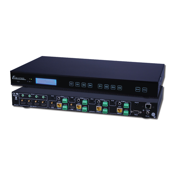
FEATURES INTRODUCTION The EVMX4K04 is a professional 4x4 HDBaseT Matrix Switcher that accommodates 4 HDMI inputs, 4 HDBaseT with 2 mirrored HDMI outputs, and 4-analog audio outputs, with IR and RS232 for each zone as well as IR, RS232 and IP control for the matrix. -
Page 4: Specifications
SPECIFICATIONS Input ............... 4 HDMI Input Connector ............Female HDMI Input Level ............... T.M.D.S. 2.9V~3.3V Input Impedance ............100Ω (Differential) Output ..............2 HDMI, 4 HDBaseT Output Connector ............. Female HDMI, Female RJ45(with LED indicators) Output Level ............. T.M.D.S. 2.9V~3.3V Output Impedance ............. -
Page 5: Front Panel Descriptions
FRONT PANEL DESCRIPTIONS 1. Firmware: Micro USB port for updating firmware 2. Power Indicator: Illuminates green when power on 3. IR: In-built IR sensor, receive IR signals sent from IR remote. 4. LCD Screen: Display real-time operation status. 5. INPUTS (Sources)/ Menu buttons: Normal mode: Back-lit buttons, ranging from “1” to “4” 6. -
Page 6: Back Panel Descriptions
BACK PANEL DESCRIPTIONS 1. IR ALL IN: Input port for IR control signal, connect with IR receiver, deliver IR signal to all the HDBaseT ports to control the remote devices. 2. HDMI INPUTS: HDMI input ports, 4 in total, type A female HDMI connector, connect with HDMI input source devices. -
Page 7: Connection Diagram
CONNECTION DIAGRAM 1. System should be installed in a clean environment and has a proper temperature and humidity. 2. All of the power switches, plugs, sockets and power cords should be insulated and safe. 3. All devices should be connected before power on. CONNECT AND OPERATE 1. -
Page 8: Front Panel Button Control
CONNECTION WITH HDBASET POH RECEIVER The EVMX4K04 boasts 4 HDBaseT output ports which support PoH. Connect the HDBT output ports of 4K HDBaseT 4x4 Matrix Switcher to the HDBaseT Receivers supporting PoH (like EVRXHD1) via twisted pair. Plug a power supply to the power port of 4K HDBaseT 4x4 Matrix Switcher, the HDBaseT Receivers will be powered by the matrix through thesingle twisted pair cable. - Page 9 EDID This matrix features EDID management to maintain compatibility between all devices. It can be controlled via EDID learning and EDID presets. EDID Learning (from output): One input port learns the EDID data of one output port Operation: Press EDID, SOURCES +OUTPUTS +ENTER. Example: Input 2 learns EDID data from output 4 All input ports learn EDID data from one output port Operation: Press EDID, ALL+OUTPUTS +ENTER Example: All input ports learn EDID data from output 4...
- Page 10 Output check Press any output button to check its corresponding input. Example: Check which one is the corresponding input for output 2. (Presume Output 2 corresponds to Input Operation: Press Output 2 button, LCD screen display AV: 1->2 IR: 1->2, and indicators of input 1 and output 2 turn on and last for 3 seconds.
-
Page 11: Remote Control
REMOTE CONTROL 1. Standby button, press it to enter/ exit standby mode 2. Input channels, range from 1~4 (buttons 5~8 are not available), corresponding IR signal switched synchronously when switching input channels. 3. Menu buttons, ALL, EDID and CLEAR, same with the corresponding front panel buttons. - Page 12 CONTROLL FAR-END DEVICE LOCALLY Connect an IR receiver to IR IN/ IR ALL IN on the switcher, and use the IR Remote of far-end device to control the device locally. 1 to 1: (through IR IN) Connect an IR receiver with IR carrier to the IR IN port of 4K HDBaseT 4x4 Matrix Switcher, users can control far-end output displayer via its IR remote from local.
- Page 13 CONTROL LOCAL DEVICE REMOTELY Connect IR receiver(s) to IR IN on far-end HDBT receiver(s), and IR Emitter(s) to IR OUT port of the switcher, and use the IR Remote of local source to control the device remotely. 1 to 1: Connect an IR receiver to IR IN on far-end HDBT receiver, and an IR Emitter to IR OUT port of the switcher.
- Page 14 CONTROL LOCAL DEVICE LOCALLY Connect IR receiver(s) to IR IN port of 4K HDBaseT 4x4 Matrix Switcher, and IR Emitter(s) to IR OUT port of the switcher, and use the IR Remote of local source to control. Connect an IR receiver to IR IN of local matrix, and an IR Emitter to IR OUT port of the switcher. Use the IR Remote of local source to control the device locally.
- Page 15 RS232 CONTROL CONNECTION WITH RS232 COMMUNICATION PORT Except the front control panel, the 4K HDBaseT 4x4 Matrix Switcher can be controlled by far-end control system through the RS232 communication port.This RS232 communication port is a female 9-pin D connector. The definition of its pins is listed in the table below. Number Function Unused...
- Page 16 CONTROL 3rd PARTY DEVICE FROM LOCAL Connect the RS232 (3-pin pluggable terminal block) port in any zone to PC, and connect the controlled RS232 device (3rd party device) to the corresponding (same zone as PC) receiver, see below: CONTROL 3rd PARTY DEVICE FROM REMOTE Connect the RS232 (3-pin pluggable terminal block) port in any zone to controlled device (3rd party device), and connect PC to the corresponding (same zone as controlled device) receiver, see below: www.vanco1.com...
-
Page 17: Tcp/Ip Control
TCP/IP CONTROL The Evolution HDBaseT 4x4 Matrix Switcher boasts an option TCP/IP port for IP control. Default settings: IP: 192.168.0.178; Subnet Mast: 255.255.255.0; Gateway: 192.168.0.1; Serial Port: 4001. IP& gateway can be changed as you need, Serial Port cannot be changed. Connect the Ethernet port of control device and TCP/IP port of 4K HDBaseT 4x4 Matrix Switcher, and set same network segment for the 2 devices, users are able to control the device via web-based GUI or designed TCP/IP communication software. - Page 18 Controlled by PC(s) in LAN Connect 4K HDBaseT 4x4 Matrix Switcher, a router and several PCs to setup a LAN (as shown in the following figure). Set the network segment of 4K HDBaseT 4x4 Matrix Switcher to the same as the router’s, then PCs within the LAN are able to control 4K HDBaseT 4x4 Matrix Switcher.
- Page 19 Main: Interface shown after logging in, provide intuitive I/O connection switching. See the screenshot below: The button matrix displays every possible connection between every input and output, users can carry on the connections by clicking corresponding button. Buttons 1~9 at the right-bottom corner provides quick saving and recall for overall connection status. Users: Display or modify credential settings, front panel lock, and GUI version.
- Page 20 Configuration: Set HDCP Compliance status for every input, and manage EDID. See the screenshot below. Network: Inquire and configure network settings including MAC address, IP address, subnet mask, and Gateway Note: Log in as user access main interface only. www.vanco1.com...
-
Page 21: Troubleshooting
TROUBLE-SHOOTING 1. PROBLEM: Color loss or no video signal output. CAUSE: The connecting cables may not be connected correctly or it may be broken. SOLUTION: Check whether the cables are connected correctly and in working condition. 2. PROBLEM: No output image when switching. CAUSE: No signal at the input / output end. Solution: Check with oscilloscope or multi-meter if there is any signal at the input/ output end. -
Page 22: Liability Statement
4. If you are still encountering issues, attempt the “hot-plug concept. With all of the HDMI cables disconnected, turn on the source and plug in the HDMI cable into it’s output, then power up the Vanco unit and plug the HDMI cable into it’s input, finally turn on the display and plug the HDMI cable from the receiver into it. -
Page 23: Limited Warranty
If repairs are needed during the warranty period the purchaser will be required to provide a sales receipt/sales invoice or other acceptable proof of purchase to the seller of this equipment. The seller will then contact Vanco regarding warranty repair or replacement. - Page 24 ® Vanco International 506 Kingsland Drive Batavia, Illinois 60510 call: 800.626.6445 fax: 630.879.9189 visit: www.vanco1.com...
Need help?
Do you have a question about the Evolution EVMX4K04 and is the answer not in the manual?
Questions and answers