
Subscribe to Our Youtube Channel
Related Manuals for Vanco Evolution EVMX44PRO


Summary of Contents for Vanco Evolution EVMX44PRO
- Page 1 4K HDBaseT ™ M A T R I X with ARC, IR, IP and RS-232 4K 4x4 HDBaseT™ Audio and Video Matrix Switcher with ARC, IR, IP and RS-232 Part Number: EVMX44PRO www.vanco1.com • 800.626.6445...
- Page 2 DEAR CUSTOMER Thank you for purchasing this product. For optimum performance and safety, please read these instructions carefully before connecting, operating or adjusting this product. Please keep this manual for future reference. This product is 100% inspected and tested in the United States to verify HDMI performance parameters.
-
Page 3: Package Contents
INTRODUCTION The Evolution by Vanco EVMX44PRO 4K 4x4 HDBaseT™ Audio and Video Matrix Switcher with ARC, IR, IP and RS-232 allows 4 HDMI sources to be distributed to up to 4 displays simultaneously, with mirrored HDMI outputs for a total of 8 outputs! The EVMX44PRO is capable of transmitting 4K@60Hz, 4:4:4 Chroma Subsampling, and HDR up to 131ft/40m over a single Cat6 cable, and 4K@60Hz, 4:4:4 Chroma Subsampling with HDR10 and Dolby Vision on the HDMI inputs and HDMI outputs. -
Page 4: Specifications
SPECIFICATIONS Video Input ..............(4) HDMI Video Input Connector ..........(4) Type-A Female HDMI Video HDMI Input Resolution ........Up to 4K@60Hz 4:4:4, HDR10, Dolby Vision Video Output ............. (4) HDBaseT, (4) HDMI Video Output Connector ..........(4) RJ45, (1) Type-A female HDMI Video HDMI Output Resolution ........ - Page 5 SPECIFICATIONS Crosstalk Isolation ............. SPDIF: < -70 dB, 10KHz sine at 0dBFS level (or max level before clipping); L+R: < -80 dB, 10KHz sine at 0dBFS level (or max level before clipping) L+R Level Deviation............ L+R: < 0.3dB, 1KHz sine at 0dBFS level (or max level before clipping) Frequency Response Deviation ........
-
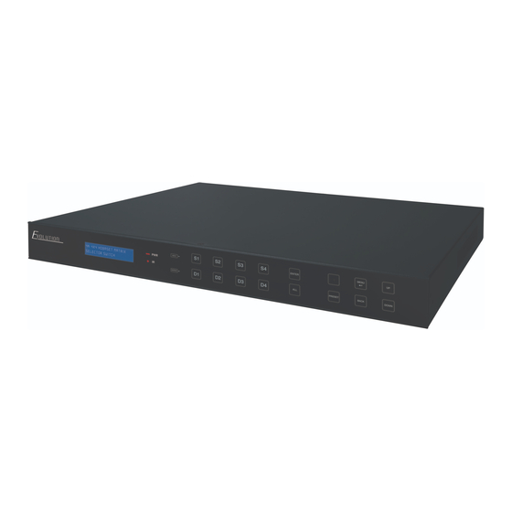
Page 6: Panel Descriptions
PANEL DESCRIPTIONS Front Panel LCD Screen: Shows current status as well as menu options POWER LED: Illuminates red when the device is in standby mode, illuminates green when device is powered on IR Sensor and its LED: Illuminates RED when the IR sensor receives an IR signal from the IR remote to control the matrix switcher (the IR sensor is on the right side of the LED) INPUT: Inputs 1-4 for input source selection OUTPUT: Outputs 1-4 for output display selection... -
Page 7: Rear Panel
Rear Panel INPUTS: Connect HDMI sources to each corresponding HDMI input IR IN: • 1-4: Connect the included IR Receivers (RXs) to each port, the number on the IR input corresponds to the HDBaseT outputs. Connect this if you would like to control the display(s) over HDBaseT (receiver(s) have IR outputs) •... -
Page 8: Connect And Operate
CONNECT AND OPERATE Connect HDMI sources to the HDMI inputs of the EVMX44PRO (NOTE: HDMI certified cables are strongly recommended for 4K HDR resolution) Connect Cat6 cables from the matrix unit outputs to each display location (NOTE: home run Cat6 cables are strongly recommended as any coupling points such as punch down RJ45 jacks, female/female RJ45 jacks, etc. -
Page 9: Front Panel Control
FRONT PANEL CONTROL The EVMX44PRO can be controlled by using the buttons on the front panel. Whenever a command is accepted, the selected input/output buttons will blink three times to confirm. 5.1 Signal Switching (S= Source; D= Display) • Switch an input to an output Operation: INPUT# + OUTPUT# + MENU Example: Switch Input 1 to Output 2: Press... -
Page 10: Lcd Screen
5.3 Status Information Inquiry Press enter status Press information tab Press navigation buttons to check the previous or next setting LCD Screen Description Shows current input/ output routing Shows status of HDMI inputs (Y= input source connected; N= no input source connected) Shows status of HDBaseT outputs... -
Page 11: Edid Management
5.4 EDID Management The Extended Display Identification Data (EDID) is used by the source device to match its video resolution with the connected display. By default, the four source inputs have the following EDID: 4K@60Hz HDR 2CH. • Enter EDID management tab: to select EDID Management Press Press... - Page 12 • To copy the EDID data from one HDMI output to one or several inputs: Example: Input 1 and 2 learn the EDID data of HDMI output 4 Select Press to confirm Press OUTPUT 4 to confirm • EDID Table: There are eleven type of built-in EDID date that can be activated, as shown below: EDID Video Format...
-
Page 13: Audio Setting
5.5 Audio Setting The matrix switcher provides four analog L+R audio output ports and four digital optical/SPDIF output ports for audio de-embedding. The audio source selection of these eight audio output ports, and the L+R audio volume can be controlled by the front panel buttons. •... -
Page 14: Preset Setting
• L+R Output Audio Volume Control Example: Set the audio volume of L+R OUT 2 port to select Press Press to select L+R OUT 2 Vol Press to enter the tab. Press Press to enter the setting tab Press to set the volume value Press to confirm 5.4 Preset Setting... -
Page 15: User Interface Control
• Recall a saved preset Example: Recall the saved preset 2 Press Press INPUT 2 to select Preset 2 Press to confirm 5.7 IP Address Inquiry Press Press to select Press to confirm USER INTERFACE CONTROL The matrix switcher can be controlled via TCP/IP. Connect the EVMX44PRO to a router or ethernet switch to connect to the local network. - Page 16 When using the GUI for the first time, an admin password must be set, and then click “Save” to enter the below login tab. Be sure to record the password(s). The UI is available in two formats, one as a master for the integrator and/or admin, and another for end users that restricts access to only switching inputs/outputs: Username Password...
-
Page 17: Switching Tab
6.1 Switching Tab Use the 4x4 button grid on the page to set which inputs are directed to which outputs. For example, clicking the button on the Input 1 row and Output 1 column, directs input 1 to output 1. Use the 9 numbered buttons under scene area to save and load layout presets. -
Page 18: Audio Tab
6.2 Audio Tab • Audio Source Selection There are eight audio sources can be selected for four analog L+R audio output ports, audio sources can be selected for four digital SPDIF output ports. • L+R Output Audio Volume Control Adjust L+R output audio volume by the volume bar and the three buttons on the right side www.vanco1.com... -
Page 19: Configuration Tab
6.3 Configuration Tab 6.3.1 Downscaling Enable/disable video resolution down-scaling function of HDMI output 1~4 ports. When enabling down-scaling, the 4K input can be automatically degraded to 1080p output for compatibility with 1080p display which is connected to the HDMI output port 6.3.2 HDCP Setting Set the HDCP mode of HDMI and HDBaseT outputs to Passive or Active Mode... - Page 20 Click confirm to save any changes or click cancel to cancel any changes that have been made 6.3.3 EDID Copy Copy the EDID data from a single output port to one or several input ports Operation: Select one output port Select one or several input ports.
- Page 21 6.3.4 EDID Setting Click EDID Setting to enter the below section to set a predefined EDID for input ports Select a built-in EDID for one or several input ports. Operation: Select a built-in EDID Select one or several input ports. Press ALL to select all input ports Click Confirm to save setting Upload user-defined EDID by the below steps: Prepare the EDID file (.bin) on the control PC.
- Page 22 6.4 RS-232 Tab • Send RS-232 commands to control third-party devices which are connected to the far-end HDBaseT receivers Select a built-in EDID for one or several input ports. Operation: Select the HDBaseT port which is connected to HDBaseT receiver which must have third-party device attached Set the baud rate Typing the commands in the box to control the selected remote third-party device which is connected to...
-
Page 23: Interface Tab
6.5 Interface Tab • Inputs and outputs can be renamed to make it easier when switching sources to displays. Simply type in the new name for each input/output, then click “Confirm” 6.6 Network Tab • Adjust to Static IP or Dynamic Host Configuration Protocol (DHCP) •... -
Page 24: Access Tab
6.7 Access Tab • Here you can change the admin password, and lock the front panel” 6.8 GUI Upgrade Type in http://192.168.0.178:100 on a web browser of a connected PC for GUI online upgrade. Type the username and password (the same as the GUI log-in setting, modified password will be available only after rebooting) to login the configuration interface. - Page 25 7 IR Control 7.1 IR Remote Control Connect IR receiver to the IR EYE port on the back of the EVMX44PRO, the matrix can be controlled by the included IR remote Enter/exit standby mode Blinking red when a button is pressed Video source selection buttons Output channel selection buttons Menu buttons:...
- Page 26 7.2 IR Pass-through Control The matrix switcher supports bi-directional IR pass-through, allowing the devices to be controlled by both source and display ends. This section provides connection and switching examples to illustrate possible configurations. 7.2.1 Control Local Input Device from Remote The local input source device can be controlled from the remote receiver location.
- Page 27 7.2.2 Control Remote Output Device from Local The remote displays can be controlled from the local matrix switcher location. • Control remote device through IR IN port Example: Switch HDMI input 3 to HDBaseT output 3. Connect an IR receiver to IR IN 3 port on the matrix switcher, then connect an IR emitter to the IR OUT on the receiver, as shown in the diagram below: •...
- Page 28 7.2.3 Integration with 3rd Party Control The EV-IRMST IR integration cable is included with the matrix unit. Seamlessly integrate IR from the EVMX8X6 with third party control systems and other IR products to provide a cleaner, faster installation. Eliminates the need to cut and splice wires or tape emitters and receivers together. Simply plug the red connector into the EVMX8X6 and the black connector into the 3rd party control system or IR system.
- Page 29 8.1.2 Control the Matrix Switcher from Remote To control the matrix switcher from a remote location, please connect one or more PCs to the RS-232 ports of HDBaseT receivers with the 3-pin to DB9 RS-232 Cables. The matrix switcher can be controlled by any one of PCs, the connection diagram is shown as below: Note: The command “RS232RCM[X]ON.”...
-
Page 30: Firmware Upgrade
8.1.4 Control the Local Third-party Device from Remote To control a local third-party device from remote, first determine which HDBaseT receiver is connected to (1 in the diagram below). Next, connect a PC to the RS-232 port of HDBaseT receiver with 3-pin to DB9 RS-232 Cable, then connect a third-party device (e.g. -
Page 31: Limited Warranty
If repairs are needed during the warranty period the purchaser will be required to provide a sales receipt/sales invoice or other acceptable proof of purchase to the seller of this equipment. The seller will then contact Vanco regarding warranty repair or replacement. - Page 32 ® Vanco International 506 Kingsland Drive Batavia, Illinois 60510 call: 800.626.6445 fax: 630.879.9189 visit: www.vanco1.com...
Need help?
Do you have a question about the Evolution EVMX44PRO and is the answer not in the manual?
Questions and answers