Table of Contents
Advertisement
Quick Links
DESCRIPTION
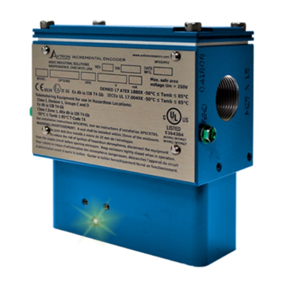
The Avtron Model XP5 SMARTSafe™ sensor is an incremental
encoder for hazardous atmosphere applications (also known as
tachometer or rotary pulse generator), allowing operation down to zero
RPM. It provides a specific number of electrical Pulses Per Revolution
(PPR) that are proportional to a shaft's revolution. The XP5 SMARTSafe
sensor is a bearingless, couplingless, modular design, providing
unequaled reliability and mechanical performance.
An XPH encoder consists of multiple parts: a rotor and a removable
XP5 sensor module designed to be imbedded within or mounted on
OEM machines and an optional flange-mounting stator housing and
optional rotor mounting/riser shaft.
The XPH utilizes XP5 magnetoresistive sensors. This proven
technology is ideal for rugged environments since it is immune to
many contaminants that cause optical encoders to fail. All of the XP5
electronics are potted, providing full protection against liquids.
The outputs are protected against short circuits and wiring errors. An
Avtron XPH SMARTSafe encoder has a two-phase output (A,B) 90° out
–
of phase, with complements (A
, B
–
pulse with complement (Z, Z
).
The XP5 removable sensor assembly has a diagnostic package
that includes Adaptive Electronics and a Fault-Check LED. With this
package, the SMARTSafe encoder can maintain itself, and let you
know if there is a problem before the problem causes unscheduled
downtime.
XP5 Sensor Part Numbers
Model
Style
6- 5-24V in/out (7272)
XP5-
1-
w/bottom
mount bracket,
8- Hi Power 5-24V in/
compatible with
5-24V out (Hx)
64mm rotor
2-
w/side-mount
brackets, com-
patible with
222mm rotor,
12.5" C-face
housing
8-
w/side-mount
brackets, com-
patible with
143mm rotor,
8.5" C-face
housing
Model: SMARTSafe
Encoder Instructions
–
), (A Quad B Output), and a marker
Line Driver
PPR
BC-50
A3-2000
AF-60
A4-2048
AK-80
A5-2500
AG-100
AT-3072
AH-120
A7-3600
AA-128
AD-4096
AM-200
A8-4800
AL-240
A9-5000
AN-256
00-
AP-300
AE-360
AC-400
AB-480
AQ-500
AR-512
AS-600
AU-720
AV-900
AJ-960
AW-1000
AY-1024
AZ-1200
CX-1500
XP5 Modular Sensor
TM
ADAPTIVE ELECTRONICS
A perfect duty cycle consists of a waveform whose "high" and "low"
conditions are of the same duration (50%/50%). It is possible over time
for the duty cycle and edge separation to change due to component
drift, temperature changes, or mechanical wear. The Adaptive
Electronics extend the life of the XP5 by constantly monitoring and
correcting duty cycle and edge separation over time.
INSTALLATION
WARNING
Installation should be performed only by qualified
personnel. Safety precautions must be taken to ensure
machinery cannot rotate and all sources of power are
removed during installation.
Refer to the following attached installation drawing XP5CRT05 for
installation information appropriate for specific hazardous locations.
NOTE
The equipment is intended for a fixed installation and
should be mounted so as to avoid electrostatic charging.
The XP5 is not considered as a safety device and is
not suitable for connection into a safety system.
It is the responsibility of the end user to ensure that the XP5 and XPH
encoder is selected correctly for the potentially explosive atmosphere
in which the equipment is to be put into service.
Connection Options
Terminal Box
Left Exit
Right Exit
M25 thread
Blanking
A-
Blanking plug
plug
B-
M25 thread
Left/Right are
as viewed
with the prod-
Special
uct label read-
able (terminal
box at top)
XP5-MAN
1
Modifications
000- none
Phasing
A->B CCW
004- Super Magnetic Shielding
A->B CCW
Advertisement
Table of Contents

Related Manuals for Avtron SMARTSafe XP5


Summary of Contents for Avtron SMARTSafe XP5
- Page 1 NOTE The outputs are protected against short circuits and wiring errors. An The equipment is intended for a fixed installation and Avtron XPH SMARTSafe encoder has a two-phase output (A,B) 90° out – – should be mounted so as to avoid electrostatic charging.
- Page 2 GENERAL MOUNTING THE ROTOR The sensor must be located accurately to properly center it on the Mount the riser shaft on top of the machine shaft. rotor and provide the correct sensor-to-rotor air gap without permitting 8A. For TDS 11SA, the riser shaft is mounted using separate (2) contact between the stationary sensor and spinning rotor.
- Page 3 GENERAL drive or accessory end of the motor. From this position, the sensor This section describes routine maintenance for the Avtron XP5 sensor. diagnostic LED can also be seen. See pinout and phasing tables for For support, contact Avtron’s field service department at 216-642- exceptions.
- Page 4 TROUBLESHOOTING If the drive indicates a loss of encoder/tach fault and the XP5 fault- check LED is not illuminated, check the encoder power supply. If power is present, check polarity; one indicator of reversed power supply is that all outputs will be high at the same time. If the drive indicates encoder fault, but the LED shows GREEN, then check the wiring between the drive and the encoder.
- Page 5 SPECIFICATIONS Electrical Specifications Units ELECTRICAL Input Voltage 5-24 5-24 A. Operating Power (Vin) Nom Output Voltage 5-24 5-24 1. Volts ......5-24V VIn 2. Current ......400mA Max @ 5V (plus cable load) Line Driver 7272 200mA Max @ 12V (plus cable load) Output Resistance Typ ohms 100mA Max @ 24V (plus cable load)
- Page 6 OUTLINE DIMENSIONS AND OPTION DETAILS XP5 Mounting Style 1 XP5 Installed as part of XPH1 Encoder XP5 SENSOR XP5 SENSOR Mounting Style “1” - Section View as Installed. TDS 10/11 Mounting Style “1” - Section View as Installed. TDS 10/11 Subassembly View Subassembly View Mounting Style “1”- Assembly View, TDS 10/11...
- Page 7 REVISION THIS DOCUMENT MUST BE PROVIDED TO THE CUSTOMER AS PART OF THE INSTRUCTION MANUAL OR AS A SEPARATE DOCUMENT. ECN NO. DESCRIPTION DATE APPROVED APPROVALS: ADD NOTE: "FOR 1/2 AND 3/4 NPT BLANKING 10/10/17 EA1328 WOLFF ATEX per Certificate No. DEMKO 17 ATEX 1880X PLUGS..."...
- Page 8 OUTLINE DIMENSIONS AND OPTION DETAILS XP5 Installed as part of XPH1 Encoder All Dimensions showing inches [mm] These instructions have been reviewed and the product evaluated as suitable for our application. Company Name Authorized Company Representative Title Date SMARTSafe is a trademark of Nidec. Features and specifications subject to change without notice.
Need help?
Do you have a question about the SMARTSafe XP5 and is the answer not in the manual?
Questions and answers