
Related Manuals for Johnson Controls RW Series


Summary of Contents for Johnson Controls RW Series
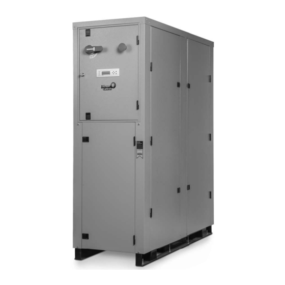
- Page 1 COMMERCIAL REVERSIBLE CHILLER RW SERIES INSTALLATION, OPERATION, MAINTENANCE Supersedes: 146.06-NOM1 (614) Form 146.06-NOM1 (1219) MODEL RW 10 TON - 50 TON 60 HZ VINTAGE D Issue Date: December 3, 2019...
- Page 2 All wiring must be in accor- dance with Johnson Controls’ published specifications and must be performed only by a qualified electrician. Johnson Controls will NOT be responsible for damage/problems resulting from improper connections to the controls or application of improper control signals.
-
Page 3: Table Of Contents
RW SERIES REVERSIBLE CHILLER INSTALLATION MANUAL Table of Contents Model Nomenclature ............. . 4 General Installation Information . -
Page 4: Model Nomenclature
RW SERIES REVERSIBLE CHILLER INSTALLATION MANUAL Model Nomenclature 15-16 RWXW Vintage Model D* - Factory Use Only RWXW – RW Series Reversible Chiller Non-Standard Options SS - Standard Unit Capacity (MBTUH) 120, 180, 240, 360, 600 Future Option N – Future Use... -
Page 5: General Installation Information
RW SERIES REVERSIBLE CHILLER INSTALLATION MANUAL General Installation Information Safety Considerations Unit Location Installing and servicing air conditioning and heating equipment can Provide sufficient room to make water and electrical connections. be hazardous due to system pressure and electrical components. - Page 6 RW SERIES REVERSIBLE CHILLER INSTALLATION MANUAL General Installation Information cont. Mounting Units Remove the unit from the wooden shipping skids (see physical dimensions). Units will be shipped with heavy duty rubber grommets to reduce sound that can be transmitted through the floor via the frame (see isolator drawing). For additional sound attenuation, use heavy duty spring isolation that can reduce sound levels by 3 dBA (see springs drawing).
-
Page 7: Physical Dimensions
RW SERIES REVERSIBLE CHILLER INSTALLATION MANUAL Physical Dimensions EMERGENCY STOP SWITCH DISCONNECT SWITCH CONTROL BOX COVER SERVICE PORTS MAIN POWER CONNECTION SOURCE WATER OUT SOURCE FX-10 WATER IN CONTROLLER DISPLAY LOAD WATER IN ACCESS DOOR LOAD WATER OUT SIDE ACCESS... - Page 8 RW SERIES REVERSIBLE CHILLER INSTALLATION MANUAL Physical Dimensions, cont. DETAIL A 25.00 24.00 52.00 24.00 SHADED AREAS REPRESENT REQUIRED CLEARANCE FOR SERVICE & MAINTENANCE OF EQUIPMENT. Model 57.0 42.0 63.1 15.9 19.5 120-180 [1448] [1067] [1603] [404] [495] [246] [33] [50.8]...
-
Page 9: Physical Data
RW SERIES REVERSIBLE CHILLER INSTALLATION MANUAL Physical Data Total Weight Refrigerant Model Compressor Charge* Shipping Installed Scroll (2) [2.4] [327] [323] Scroll (2) [3.5] [381] [384] 10.5 1130 1152 Scroll (2) [4.8] [514] [524] 17.9 1320 1388 Scroll (2) [8.1]... -
Page 10: Field Connected Water Piping
RW SERIES REVERSIBLE CHILLER INSTALLATION MANUAL Field Connected Water Piping General NOTE: The placement and connection of the water circulating pump(s) must be taken into consideration prior to designing the System piping should be kept as simple as possible to minimize final water piping systems. -
Page 11: Typical Piping
RW SERIES REVERSIBLE CHILLER INSTALLATION MANUAL RW Series Typical Piping Standard Piping Factory Installed Field Supplied and Installed Pump Isolation Valves From Load 1/4” NPT Strainer Brazed Plate Water Pressure/Temperature Heat Exchanger Temperature Port Sensors To Load Isolation Valve Note: System piping should have drain ports to enable flushing and cleaning of heat exchangers. On systems utilizing pumps with VFDs, an automatic flow control valve must be installed. -
Page 12: 1.5. Water Quality
RW SERIES REVERSIBLE CHILLER INSTALLATION MANUAL RW Series Application Data 1.0. Minimum Fluid Volume A differential pressure switch can be used in place of a fl ow switch. The differential switch must be capable of pressure Water-to-water heat pumps require a minimum amount of load range as indicated in the pressure drop tables. - Page 13 RW SERIES REVERSIBLE CHILLER INSTALLATION MANUAL RW Series Application Data cont. 1.6. Insulation 1.7. Brine Applications Heat pumps are built with factory installed insulation on any Applications where the leaving fl uid temperature goes below surface that may be subject to temperatures below the room 40°F a suitable brine solution must be used.
-
Page 14: System Cleaning And Flushing
RW SERIES REVERSIBLE CHILLER INSTALLATION MANUAL System Cleaning and Flushing Cleaning and Flushing 8.5). The specified percentage of antifreeze may also be added at this time. Use commercial grade antifreeze designed for HVAC Prior to start up of any heat pump, the water circulating system systems only. -
Page 15: Electrical Data
RW SERIES REVERSIBLE CHILLER INSTALLATION MANUAL Electrical Data Total Compressor Rated Voltage Model Unit Circ Fuse/ Fuse/ Voltage Min/Max HACR HACR 208-230/60/3 187/253 36.0 23.1 160.0 46.2 52.0 60.0 460/60/3 414/506 19.0 12.2 87.0 24.4 27.5 30.0 575/60/3 517/633 13.5 62.0... - Page 16 RW SERIES REVERSIBLE CHILLER INSTALLATION MANUAL Electrical Data cont. Transformer Figure 6: Control Box Power Supply (Field line voltage connection) Class CC Fusing for Transformer Fused / Non-Fused Disconnect FX10 Control Board Class J Fuses FX10 Expansion Board Compressor Contactor (Lower)
-
Page 17: Wiring Schematics
RW SERIES REVERSIBLE CHILLER INSTALLATION MANUAL Wiring Schematics Chiller with IntelliStart L2 (IN) L2 (OUT) L1 (IN) L1 (OUT) GROUND 24VAC Com 24VAC L2 (IN) L2 (OUT) L1 (IN) L1 (OUT) - Page 18 RW SERIES REVERSIBLE CHILLER INSTALLATION MANUAL Wiring Schematics cont. Chiller with Phase Guard GROUND 24VAC Com 24VAC...
-
Page 19: Field Wiring And Control Setup
RW SERIES REVERSIBLE CHILLER INSTALLATION MANUAL Field Wiring and Control Setup High Voltage Connections Line Voltage Power supply wiring connects directly to lugs on the topo of the Unit Power Supply 208-230/60/3, electrical disconnect. In 208-230V applications, heat pumps are 460/60/3, or 575/60/3 factory wired for 208V supply. -
Page 20: Control Features
RW SERIES REVERSIBLE CHILLER INSTALLATION MANUAL Field Wiring and Control Setup cont. Accessory Relay Setup °F or °C - Unit of Measure The accessory output set to “close” upon Y1 compressor call Degrees Fahrenheit is factory set, however degrees Celsius can be (compressor is delayed 90 sec. - Page 21 RW SERIES REVERSIBLE CHILLER INSTALLATION MANUAL Control Features Advanced Freeze Detection System enabled, and if the logic determines that a freeze condition is likely to happen based on current conditions, the compressor of The source and load heat exchangers are protected by a multi- the involved refrigerant circuit is immediately stopped.
- Page 22 RW SERIES REVERSIBLE CHILLER INSTALLATION MANUAL Control Features cont. Low Pressure (DI-3 and DI-6) Reversible Chiller Setpoint Control The low-pressure switches shall be a normally closed (NC) switch This control software is by default set to operate in ‘Aquastat’ that monitors the systems compressor suction line refrigerant mode, which requires external setpoint logic to generate the Y1 pressure.
- Page 23 RW SERIES REVERSIBLE CHILLER INSTALLATION MANUAL Control Features cont. • When the controlling temperature sensor is set to select the Load LW Temp, the setpoint control will operate strictly in a proportional mode with offsets and differentials used to determine the appropriate capacity to use. In this mode, the following parameters are used: •...
-
Page 24: Sequence Of Operation
RW SERIES REVERSIBLE CHILLER INSTALLATION MANUAL Sequence of Operation Power Fail Restart Compressor Lead/Lag When the controller is first powered up, the outputs will be Compressor lead/lag is a standard part of the FX10 control system. disabled for a random start delay. The delay is provided to prevent The unit is shipped from the factory with lead/lag enabled. -
Page 25: Inputs And Outputs Configuration
RW SERIES REVERSIBLE CHILLER INSTALLATION MANUAL Inputs and Outputs Confi guration DUAL STAGE WW Input Name Input Output Name Output Entering Load Water Temperature AI 1 Compressor 1 Leaving Load Water Temperature 1 AI 2 Compressor 2 Source Heating Freeze Detection 1... - Page 26 RW SERIES REVERSIBLE CHILLER INSTALLATION MANUAL Unit Display and Interface Cont. MUI Menu Navigation Welcome Info Temp Stat Outputs Settings Maint Alarm ALM_History Stat Info Outputs Temp Status Temperatures Log Off Outputs Unit Status Auto Enter Load 77.2 ºF Dual Stage Setpt...
- Page 27 RW SERIES REVERSIBLE CHILLER INSTALLATION MANUAL Unit Display and Interface cont. Menu and Menu Contents High Pressure 1 – Compressor Circuit 1 High Pressure Switch Alarm • If high pressure switch 1 opens at any time during compressor 1 run •...
-
Page 28: Reference Calculations
RW SERIES REVERSIBLE CHILLER INSTALLATION MANUAL Reference Calculations Heating Calculations: Cooling Calculations: LWT = EWT - LWT = EWT + GPM x 500* GPM x 500* NOTE: * When using water. Use 485 for 15% methanol/water or Environol solution. Legend... -
Page 29: Operating Parameters
RW SERIES REVERSIBLE CHILLER INSTALLATION MANUAL Operating Parameters Heating Mode Entering Entering Suction Discharge Superheat Subcooling Load Temp ( Source Temp ( Pressure (psig) Pressure (psig) 75-100 200-215 10-12 10-13 100-125 200-215 12-14 8-12 125-150 215-230 14-18 8-12 150-165 230-255... -
Page 30: Pressure Drop
RW SERIES REVERSIBLE CHILLER INSTALLATION MANUAL Pressure Drop Pressure Drop (psi) Model 30°F 50°F 70°F 90°F 110°F 4/29/14 Water Pressure Drop vs. Flow at 30°F Model 120 Model 180 Model 240 Model 360 Model 600 Flow (gpm) Note: Pressure drop is the same for load and source heat exchangers at 30°F fluid temperature. -
Page 31: Operating Limits
RW SERIES REVERSIBLE CHILLER INSTALLATION MANUAL Compressor Resistance Model 208-230 .539 / .528 /.528 .575 / .575 / .575 2.116 / 2.088 / 2.072 3.333 / 3.289 / 3.263 .32 / .32 / .33 1.29 / 1.28 / 1.33 1.99 / 1.96 / 2.05 .33 / .33 / .33... -
Page 32: Troubleshooting
RW SERIES REVERSIBLE CHILLER INSTALLATION MANUAL Troubleshooting Should a major problem develop, refer to the following information for possible causes and corrective steps. If compressor won’t run: The fuse may be open or the circuit breaker is tripped. Check electrical circuits and motor windings for shorts or grounds. Investigate for possible overloading. - Page 33 RW SERIES REVERSIBLE CHILLER INSTALLATION MANUAL Heating Cycle Analysis ______PSI = ______SAT°F ______°F Braze Plate Suction Compressor Discharge ______°F Liquid Line ______PSI = ______SAT°F Braze Plate ______°F Unit Amp Draw ____________ Entering Source Water ________°F Line Voltage _________ Entering Water Pressure Drop _____ PSI Loop:______ Open ______ Closed Leaving Source Water ________°F...
- Page 34 RW SERIES REVERSIBLE CHILLER INSTALLATION MANUAL RW Series Troubleshooting Form Company Name: _________________________________ Company Phone No: ______________________________ Technician Name: ________________________________ Date: __________________________________________ Model No: ______________________________________ Serial No:_______________________________________ Owner’s Name: __________________________________ Open or Closed Loop: _____________________________ Installation Address: ______________________________ Installation Date: _________________________________...
-
Page 35: Start-Up
RW Series Startup Job Site Recording Process Complete the top of the RW Series Start-Up Form for each unit. *Be sure to note the mode (Heat/Cool) you will be testing the unit in as well as freeze protection details of type and concentration (Test to Verify). - Page 36 RW SERIES REVERSIBLE CHILLER INSTALLATION MANUAL RW Series Start-Up Form Start-up Date Unit Model # Size: Unit Tag # Unit Serial # Start-up Company Start-Up Mode Employee Name Cooling / Heating Job Name Voltage across L1-L2 Water Side Voltage across L2-L3...
-
Page 37: Preventive Maintenance
RW SERIES REVERSIBLE CHILLER INSTALLATION MANUAL Preventive Maintenance Replacement Procedures Unit Heat Exchanger Maintenance When contacting the company for service or replacement parts, Keep all air out of the water or antifreeze solution. refer to the model number and serial number of the unit as Keep the system under pressure at all times. -
Page 38: Revision Guide
RW SERIES REVERSIBLE CHILLER INSTALLATION MANUAL Revision Guide Pages: Description: Date: Updated Dimensional Data - Added Detail 25 Jun 2014 First Published 31 Mar 2014... - Page 39 THIS PAGE INTENTIONALLY LEFT BLANK.
- Page 40 P.O. Box 1592, York, Pennsylvania USA 17405-1592 Subject to change without notice. Printed in USA Copyright © by Johnson Controls 2019 www.johnsoncontrols.com ALL RIGHTS RESERVED Form 146.06-NOM1 (1219) Issue Date: December 3 2019 Supersedes: 146.06-NOM1 (614)
Need help?
Do you have a question about the RW Series and is the answer not in the manual?
Questions and answers