
Related Manuals for Intec FORCE/3 HP2


Summary of Contents for Intec FORCE/3 HP2
- Page 1 Instruction Manual Insulation blowing machine Original Language – English Intec — 4040 Kodiak Court – Frederick, CO 80504 USA T: 303-833-6644 Web: www.inteccorp.com Email: info@inteccorp.com T: 800-666-1611 Rev Date: 20200504...
-
Page 2: Introduction
We take pride in making your job as easy and profitable as possible. The right system for your needs: Intec strives to provide you with the best combination of portability, functionality, and installation versatility to surpass your desired success. -
Page 3: Table Of Contents
Instruction Manual Table of Contents INTRODUCTION ................... 1 SYMBOLS ....................3 SAFETY FIRST ....................3 HOW THE SYSTEM WORKS ................. 4 SYSTEM SET-UP: .................... 8 SYSTEM OPERATION: ..................11 MAINTENANCE .................... 13 TROUBLESHOOTING ..................14 SPECIFICATIONS ................... 16 ELECTRICAL DRAWINGS ................... 17 MAKING A CLAIM FOR DAMAGE OR LOSS ............... -
Page 4: Symbols
Instruction Manual Symbols SYMBOL SYMBOL MEANING Indicates an imminently hazardous situation, which, if not avoided, Danger will result in death or serious injury. Indicates a potentially hazardous situation, which, if not avoided, Warning could result in death or serious injury. Indicates a potentially hazardous situation, which, if not avoided, Caution may result in minor or moderate injury. -
Page 5: How The System Works
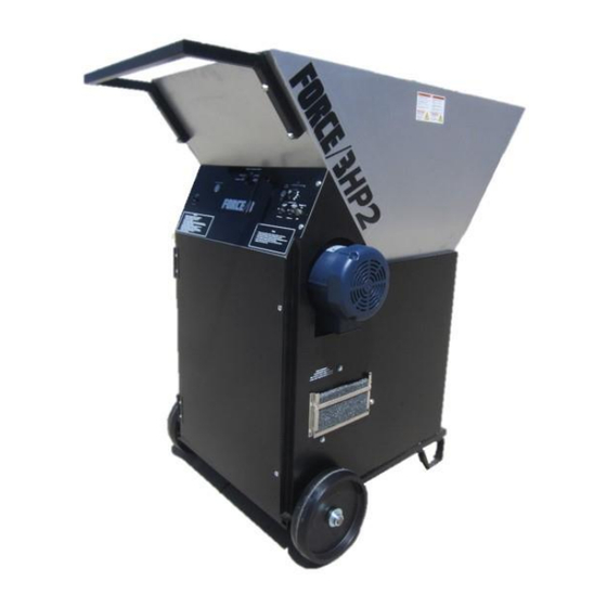
Instruction Manual How the System Works OVERVIEW: Cellulose, Fiberglass, or Stone Wool insulation is loaded into the hopper. The agitator breaks-up and starts the insulation conditioning process prior to insulation entering the airlock. The airlock transports the insulation into the airstream created by the blower system. Insulation is discharged from the airlock, through the machine outlet, and into the hose. - Page 6 Instruction Manual Primary Blower Secondary Blower Agitator / Airlock Motor Wired Remote Receptacle Electrical Receptacles: The agitator / airlock motor & each blower motor require a dedicated 115 volt 15 amp circuit. Wired Remote Receptacle: Twist lock receptacle to plug in the wired remote. Control Panel: The electrical panel, combined with the remote (wired and/or wireless), provides operation of the machine.
- Page 7 Instruction Manual GOWIRELESS: The optional GOWIRELESS LRT (Long Range Transmission) system enables wireless use. The transmitter can be mounted on wrist, hose, belt clip, lanyard, or in pocket. Agitator: The agitator is located in the bottom section of the hopper between the hopper and airlock. The configuration of the agitator enables high production rates and appropriate insulation conditioning.
- Page 8 Instruction Manual Control Panel Agitator Motor Gearbox Self-Adjusting Chain Tensioner Secondary Blower Primary Blower Airlock Drive Sprocket Airlock Backflow Preventers Backflow preventers: The backflow preventers (or one-way valves) are found in the base of the system positioned between the blower and airlock. The backflow preventers will keep insulation from flowing backwards through the airlock and into the blower which may happen when the pressure of product in the hose is more than that of the pressure in the line between the blower and airlock - examples include (i) hose moving straight up from machine to a second or third story, or (ii) during...
-
Page 9: System Set-Up
2. Power Connections: FORCE/3 HP2: Obtain three 12 gauge, heavy duty twist-lock power cords (note: when requiring over 100 feet per power cord, recommendation is to use 10 gauge in order to reduce the voltage drop and allow for appropriate operation of motors). - Page 10 3. Attach 3” hose (100 feet minimum, 150 feet is recommended to provide for additional insulation conditioning) to machine outlet using a hose clamp. Note: If you desire to wall fill, you may benefit from Intec’s Machine Insert Tube which converts your machine’s outlet to 2”; this is a recommended procedure when using cellulose (Intec’s multi-reducer hose...
- Page 11 Instruction Manual When to use variable speed blower control: Most users consider utilizing the variable speed blower control when performing wall fill applications including blow behind netting, dense pack, or spray on. The variable speed blower control adjusts the speed for the primary blower only, the second blower is either 100% on or off;...
-
Page 12: System Operation
Instruction Manual c. WIRELESS REMOTE if desire to control the system with the GOWIRELESS controls. Note: Place transmitter in jacket and mount on hose, wrist, or use lanyard to place around neck, or remove from jacket and use belt clip to fasten on belt, or carry in pocket. - Page 13 Instruction Manual Cellulose: Set bag on edge of hopper & remove plastic wrapping. Then insert insulation only into hopper. Caution - Be sure no plastic goes into hopper. Fiberglass or Stone Wool Score bag in ½ 2. Bend bag to break in ½ 3.
-
Page 14: Maintenance
Replace airlock seals if a cut or tear is evident. Airlock seals should be replaced approximately every 300 hours of operation, or once per year. Visit www.inteccorp.com or contact Intec for replacement instructions. T: 303-833-6644 800-666-1611 www.inteccorp.com... -
Page 15: Troubleshooting
Circuit breaker at power source Reset circuit breaker. has tripped. Electrical system may have a Contact Intec Tech Support loose wire. Wired remote cord & electrical Place the electrical panel panel switches need to be in blower and agitator switches in ‘ON’... - Page 16 Instruction Manual Machine is on, yet no material Slide gate is closed. Open slide gate. comes out of hose. Insulation blockage in hose. Turn system off, remove hose and clear blockage. Air pocket in hopper is Disconnect electrical power. preventing insulation from Redistribute insulation material feeding into agitators.
-
Page 17: Specifications
Instruction Manual Specifications Weight 283 lbs 175 kg Blower Dual 115 VAC, two stage Agitator Motor 1 ½ HP, 115VAC, Power Requirements 3-115VAC, 15 amp circuits For both configurations, you will require twist- lock 12/3 heavy duty power cords. If you are using over 100’, then 10/3 heavy duty power cords are recommended / required. -
Page 18: Electrical Drawings
Instruction Manual Electrical Drawings FORCE/3 HP2 Universal Sub-panel T: 303-833-6644 800-666-1611 www.inteccorp.com Original Language - English... - Page 19 Instruction Manual FORCE/3 HP2 – wired T: 303-833-6644 800-666-1611 www.inteccorp.com Original Language - English...
- Page 20 Instruction Manual FORCE/3 HP2 – wireless T: 303-833-6644 800-666-1611 www.inteccorp.com Original Language - English...
-
Page 21: Making A Claim For Damage Or Loss
Instruction Manual Making a Claim for Damage or Loss Your Intec products were carefully packed and thoroughly inspected before leaving our factory. We understand that damage to or defects with your system may unfortunately occur. Please inspect your shipment carefully upon arrival and save the shipping containers and packaging materials in case of damage. -
Page 22: Warranty
It is expressly understood and agreed that no officer, agent, salesman or employee of the manufacturer Intec (MANUFACTURER) has the authority to obligate the MANUFACTURER by any terms, stipulations, or conditions not herein expressed; that all previous representations and agreements, either verbal or written, referring to the machinery and equipment, which is the subject of this Warranty, are hereby superseded and canceled, and that there are no promises or agreements outside of the Warranty agreement.
Need help?
Do you have a question about the FORCE/3 HP2 and is the answer not in the manual?
Questions and answers