
Related Manuals for Wacker Neuson GPi 3200


Summary of Contents for Wacker Neuson GPi 3200
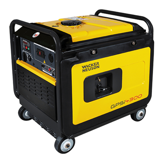
- Page 1 Operator’s Manual Inverter Generator GPi 3200 / GPSi 3200 GPi 4300 / GPSi 4300 0179740en 0311...
- Page 2 This publication may be photocopied by the original purchaser of the machine. Any other type of reproduction is prohibited without express written permission from Wacker Neuson Corporation. Any type of reproduction or distribution not authorized by Wacker Neuson Corporation represents an infringement of valid copyrights. Violators will be prosecuted. Trademarks All trademarks referenced in this manual are the property of their respective owners.
-
Page 3: Foreword
Expectations This manual provides information and procedures to safely operate and main- tain the above Wacker Neuson model(s). For your own safety and to reduce the information in risk of injury, carefully read, understand, and observe all instructions described this manual in this manual. - Page 4 Serious injury hazards to the operator and persons in the work area Permanent damage to the machine which will not be covered under warranty Contact your Wacker Neuson dealer immediately if you have questions about approved or unapproved parts, attachments, or modifications.
-
Page 5: Table Of Contents
GPi 3200 / 4300 Table of Contents Foreword Safety Information Signal Words Found in this Manual ............7 Machine Description and Intended Use ..........8 Safety Guidelines for Operating the Machine ........9 Operator Safety While Using Internal Combustion Engines ....11 Guidelines for Service Safety ............. - Page 6 Table of Contents GPi 3200 / 4300 Maintenance Periodic Maintenance Schedule ............38 Detaching the Side Panels (S Models) ..........39 Checking the Engine Oil ..............40 Cleaning the Air Cleaner ..............41 Cleaning and Checking the Spark Plug ..........42 Changing the Engine Oil ..............43 Cleaning the Spark Arrester ..............44...
-
Page 7: Safety Information
GPi 3200 / 4300 Safety Information Safety Information Signal Words Found in this Manual This manual contains DANGER, WARNING, CAUTION, NOTICE, and NOTE signal words which must be followed to reduce the possibility of personal injury, damage to the equipment, or improper service. -
Page 8: Machine Description And Intended Use
GPi 3200 / 4300 Machine Description and Intended Use This machine is a portable electric power source. The Wacker Neuson Inverter Generator consists of a gasoline engine, a fuel tank, and an electric alternator and inverter. Controls and receptacles are provided on a control panel mounted on the side of the machine. -
Page 9: Safety Guidelines For Operating The Machine
GPi 3200 / 4300 Safety Information Safety Guidelines for Operating the Machine DANGER Carbon monoxide. Using a generator indoors CAN KILL YOU IN MINUTES. Generator exhaust contains carbon monoxide (CO). This is a poison you cannot see or smell. If you can smell the generator exhaust, you are breathing CO. But even if you cannot smell the exhaust, you could be breathing CO. - Page 10 Safety Information GPi 3200 / 4300 Make sure the machine is on a firm, level surface and will not tip, roll, slide, or fall while operating. Remove all tools, cords, and other loose items from the generator before starting it.
-
Page 11: Operator Safety While Using Internal Combustion Engines
GPi 3200 / 4300 Safety Information Storing the Store the machine properly when it is not being used. The machine should be machine stored in a clean, dry location out of the reach of children. Operator Safety While Using Internal Combustion Engines WARNING Internal combustion engines present special hazards during operation and fueling. -
Page 12: Guidelines For Service Safety
Replacing Replace worn or damaged components. parts and Use only spare parts recommended by Wacker Neuson. labels Keep the fuel lines in serviceable condition. Leaking fuel and fumes are extremely explosive! Replace all missing and hard-to-read labels. -
Page 13: Label Locations
GPi 3200 / 4300 Safety Information Label Locations wc_si000348gb.fm... -
Page 14: Machine Labels
Safety Information GPi 3200 / 4300 Machine Labels Wacker Neuson machines use international pictorial labels where needed. These labels are described below. Safety and Warning Labels Ref. Label Meaning DANGER Using a generator indoors CAN KILL YOU IN MINUTES. Generator exhaust contains carbon monoxide. - Page 15 GPi 3200 / 4300 Safety Information Ref. Label Meaning WARNING To reduce the risk of injury, user must read and understand instruction manual. Exhaust gas contains poisonous carbon monoxide. Do not use in poorly ventilated area. The operator may suffer severe elecrtric shock.
- Page 16 Safety Information GPi 3200 / 4300 Ref. Label Meaning A nameplate listing the model number, item number, revision number, and serial number is attached to each unit. Please record the information found on this nameplate so it will be available should the nameplate become lost or damaged.
-
Page 17: Operation
1. Make sure all loose packaging materials have been removed from the machine. 2. Check the machine and its components for damage. If there is visible damage, do not operate the machine! Contact your Wacker Neuson dealer immediately for assistance. -
Page 18: Features And Components
Operation GPi 3200 / 4300 Features and Components wc_gr006662 wc_tx001239gb.fm... - Page 19 GPi 3200 / 4300 Operation Ref. Description Ref. Description Control panel Spark plug cap Fuel tank Air cleaner Fuel gauge Fuel strainer Right side panel (if equipped) Battery (if equipped) Oil drain plug Oil filler / gauge Recoil starter Left side panel (if equipped)
-
Page 20: Lifting And Transporting
Operation GPi 3200 / 4300 Lifting and Transporting Lifting the This generator, while compact, is heavy enough to cause injury if proper lifting Machine techniques are not used. Observe the following guidelines when lifting the generator. Do not attempt to lift and carry the generator unassisted. Use appropriate lifting equipment such as slings, chains, hooks, ramps, or jacks. -
Page 21: Installation
GPi 3200 / 4300 Operation Installation Locating the Follow the practices below when choosing an appropriate location for the generator generator. Place the generator in an area where it will not be exposed to rain, snow, or direct sunlight. Position the generator on firm, level ground so that it will not slide or shift. -
Page 22: Connecting And Maintaining The Battery
Operation GPi 3200 / 4300 Connecting and Maintaining the Battery Location and An automotive-style battery (n) is installed on the machine. The battery is located description next to the air cleaner. wc_gr006680 WARNING Explosion hazard. Batteries can emit explosive hydrogen gas. -
Page 23: Use Of Extension Cords
GPi 3200 / 4300 Operation Do not disconnect the battery while the machine is running. Do not attempt to run the machine without a battery. Do not attempt to jump-start the machine. In the event that the machine has a discharged battery, either replace the battery with a fully charged battery or charge the battery using an appropriate battery charger. -
Page 24: Power Requirements
The information in the following chart is offered only as a general guideline to help starting power you determine power requirements for different types of equipment. Contact your requirements nearest Wacker Neuson dealer, or the manufacturer or dealer of the tool or equipment, with questions regarding power requirements. Equipment type Wattage needed to start... -
Page 25: Control Panel
GPi 3200 / 4300 Operation 2.10 Control Panel GPi 3200 GPi 4300 GPSi 3200 GPSi 4300 AC 120V GPi 3200 (CSA) GPi 4300 (CSA) wc_gr006675 wc_tx001239gb.fm... - Page 26 Operation GPi 3200 / 4300 Ref. Description Ref. Description Multi monitor Operation hour indicator light AC receptacles, 20A Voltage indicator light AC receptacle, 30A Frequency indicator light Ground lug LED display changeover switch DC terminals Auto-power saving switch DC circuit breaker...
- Page 27 GPi 3200 / 4300 Operation LCD (j) The LCD (j) displays machine operating status such as voltage, frequency, and operating hours. The LCD also displays O_Lod when the generator is in an overload condition. The green LCD changeover switch (n) allows the operator to cycle through the changeover various machine status modes described above.
-
Page 28: Customer Connections
Operation GPi 3200 / 4300 2.11 Customer Connections Description The generator is equipped with: one 120V 20A duplex receptacle (b) with a ground fault circuit interrupt (GFI) one 120V 30A twist-lock receptacle (c) one pair of DC terminals (e) exclusively intended for charging 12V automotive- style batteries. -
Page 29: Grounding The Generator
GPi 3200 / 4300 Operation 2.12 Grounding the Generator Location The ground lug (d) is located to the right of the DC terminals. wc_gr006664 Function This ground connection is used for electrically grounding the generator when necessary to comply with the National Electrical Code and other federal, state, and local regulations. -
Page 30: Fueling The Machine
Operation GPi 3200 / 4300 2.13 Fueling the Machine Fuel filler cap The fuel filler cap (C) is located on top of the fuel tank. Turn the fuel filler cap counter-clockwise to open; clockwise to close. wc_gr006665 WARNING Fire/burn hazards. Gasoline is flammable and can ignite or explode. -
Page 31: Before Starting
GPi 3200 / 4300 Operation 2.14 Before Starting DANGER Carbon monoxide. Using a generator indoors CAN KILL YOU IN MINUTES. Generator exhaust contains carbon monoxide (CO). This is a poison you cannot see or smell. If you can smell the generator exhaust, you are breathing CO. But even if you cannot smell the exhaust, you could be breathing CO. -
Page 32: Starting The Generator (S Models)
Operation GPi 3200 / 4300 2.15 Starting the Generator (S Models) CAUTION Personal injury or machine damage hazards. Starting the generator with equipment attached can damage the generator or the equipment. Unexpected equipment start-up can cause personal injury. Disconnect all equpment from the generator before starting it. -
Page 33: Starting The Generator (Manual Start Models)
GPi 3200 / 4300 Operation 2.16 Starting the Generator (Manual Start Models) CAUTION Personal injury or machine damage hazards. Starting the generator with equipment attached can damage the generator or the equipment. Unexpected equipment start-up can cause personal injury. Disconnect all equpment from the generator before starting it. -
Page 34: Using Ac Power
Operation GPi 3200 / 4300 2.17 Using AC Power Prerequisites Verify that the engine is operating. Verify that the voltage displayed on the LCD (j) is approximately 120V. Turn off the equipment to be connected to the generator. Confirm that the equipment to be connected to the generator does not exceed the maximum rated power output and specifed amperage. -
Page 35: Using Dc Power
GPi 3200 / 4300 Operation 2.18 Using DC Power Overview The DC terminals (e) are to be used only for charging 12V batteries. Maximum available power is 12V–8.3A (100W). WARNING Risk of machine damage and electric shock. Do not use AC power and DC power at the same time. -
Page 36: Stopping The Generator
Operation GPi 3200 / 4300 Connecting Follow the procedure below to connect and charge a battery. and charging 1. Connect the positive terminal (e1) (red) on the generator to the positive (+) a battery battery terminal. 2. Connect the negative terminal (e2) (black) on the generator to the negative (-) battery terminal. -
Page 37: Emergency Shutdown Procedure
GPi 3200 / 4300 Operation 2.20 Emergency Shutdown Procedure Procedure If a breakdown or accident occurs while the machine is operating, follow the procedure below: 1. Stop the engine. 2. Turn off the fuel supply. 3. Disconnect tools from the machine. -
Page 38: Maintenance
Overhaul engine Check generator rotor Check generator stator Replace engine mount 1 Perform initial oil change after first 20 hours of operation. 2 Refer to the engine service manual or consult an authorized Wacker Neuson service center 3 Replace yearly wc_tx001240gb.fm... -
Page 39: Detaching The Side Panels (S Models)
GPi 3200 / 4300 Maintenance Detaching the Side Panels (S Models) Description Electric start machines are equipped with two sound attenuation panels. The panels remain in place during normal operation. The left side panel (p) must be detached and removed to perform routine maintenance. -
Page 40: Checking The Engine Oil
Maintenance GPi 3200 / 4300 Checking the Engine Oil When Check engine oil daily before starting the engine, or more than 5 minutes after stopping the engine. Prerequisites Engine is stopped Machine is on a level surface Fresh oil is available (see Technical Data for type and quantity) WARNING Burn hazard. -
Page 41: Cleaning The Air Cleaner
GPi 3200 / 4300 Maintenance Cleaning the Air Cleaner When Clean the air cleaner every 50 hours of operation. Prerequisite Engine is stopped and cool to the touch Description The air cleaner assembly consists of two urethane forms housed inside the air cleaner body. -
Page 42: Cleaning And Checking The Spark Plug
Maintenance GPi 3200 / 4300 Cleaning and Checking the Spark Plug When Clean the spark plug and check the electrode gap every 200 hours of operation (monthly). Prerequisite Engine is stopped and cool to the touch WARNING Burn hazard. Engine and exhaust pipe become extremely hot during operation. -
Page 43: Changing The Engine Oil
GPi 3200 / 4300 Maintenance Changing the Engine Oil When Change the engine oil after the first 20 hours of operation, and every 50 hours thereafter. Prerequisites Engine is stopped, but still warm Machine is on a level surface Fresh engine oil (see engine operator’s manual) -
Page 44: Cleaning The Spark Arrester
Maintenance GPi 3200 / 4300 Cleaning the Spark Arrester When Clean the spark arrester after every 100 hours of operation. Prerequisite Engine is stopped and cool to the touch Description The spark arrester is a cylindrical metal element fastened inside the exhaust outlet. -
Page 45: Cleaning The Fuel Strainer
GPi 3200 / 4300 Maintenance Cleaning the Fuel Strainer When Clean the fuel strainer monthly, or after every 200 hours of operation. Prerequisite Engine is stopped and cool to the touch. Description The fuel strainer (M) removes dirt and water from the fuel before it enters the carburetor. -
Page 46: Storing The Generator
Maintenance GPi 3200 / 4300 Storing the Generator When Follow the procedures described below if you intend to take your generator out of service and store it for at least six months. Tasks The following tasks must be performed in order to prepare the generator for storage: 1. - Page 47 GPi 3200 / 4300 Maintenance 4. Reconnect the fuel line to the fuel strainer. 5. Dispose of drained fuel. Draining the 6. Place a plastic cloth and a collection container beneath the machine. carburetor wc_gr006674 7. Locate the fuel drain screw (a). The screw is either recessed or exposed depending on your machine model.
-
Page 48: Schematics
Schematics GPi 3200 / 4300 Schematics Electrical Schematic (S Models, non-CSA) wc_gr006681 wc_tx001241gb.fm... -
Page 49: Electrical Schematic Components (S Models, Non-Csa)
GPi 3200 / 4300 Schematics Electrical Schematic Components (S Models, non-CSA) Component Component Engine Monitor control unit Generator Engine switch Control panel AC receptacle, 120V 20A Diode rectifier Ground terminal Coil (1) Stepping motor Coil (2) Oil level sensor Coil (3) -
Page 50: Electrical Schematic (Csa)
Schematics GPi 3200 / 4300 Electrical Schematic (CSA) wc_gr007295 wc_tx001241gb.fm... -
Page 51: Electrical Schematic Components (Csa)
GPi 3200 / 4300 Schematics Electrical Schematic Components (CSA) Component Component Engine Monitor control unit Generator Engine switch Control panel AC receptacle, 120V 20A Diode rectifier Ground terminal Coil (1) Stepping motor Coil (2) Oil level sensor Coil (3) Ignition coil... -
Page 52: Electrical Schematic (Manual Start Models, Non-Csa)
Schematics GPi 3200 / 4300 Electrical Schematic (Manual Start Models, non-CSA) wc_gr006848 wc_tx001241gb.fm... -
Page 53: Electrical Schematic Components (Manual Start Models, Non-Csa)
GPi 3200 / 4300 Schematics Electrical Schematic Components (Manual Start Models, non-CSA) Component Component Engine DC output terminal Generator Micro switch Control panel Inverter and engine control unit Diode rectifier Monitor control unit Coil (1) Engine switch Coil (2) AC receptacle, 120V 20A... -
Page 54: Electrical Schematic (Manual Start Models, Csa)
Schematics GPi 3200 / 4300 Electrical Schematic (Manual Start Models, CSA) Brn/W Grn/Y Grn/Y Grn/Y Grn/Y wc_gr007415 wc_tx001241gb.fm... -
Page 55: Electrical Schematic Components (Manual Start Models, Csa)
GPi 3200 / 4300 Schematics Electrical Schematic Components (Manual Start Models, CSA) Component Component Engine DC output terminal Generator Micro switch Control panel Inverter and engine control unit Diode rectifier Monitor control unit Coil (1) Engine switch Coil (2) AC receptacle, 120V 20A... -
Page 56: Basic Troubleshooting
Basic Troubleshooting GPi 3200 / 4300 Basic Troubleshooting Problem Cause Remedy Engine is difficult to 1. Fuel is contaminated 1. Clean fuel filter and fuel tank. start Remove water, dirt, and other 2. Spark plug gap setting is impurities. incorrect 2. -
Page 57: Technical Data
GPi 3200 / 4300 Technical Data Technical Data Engine Engine Power Rating Engine power rating per ISO/TR 14396. Actual power output may vary due to conditions of specific use. Model GPi 3200 GPSi 3200 GPi 4300 GPSi 4300 Engine Engine make... -
Page 58: Generator Data
Technical Data GPi 3200 / 4300 Generator Data Machine GPi 3200 GPSi 3200 GPi 4300 GPSi 4300 Machine Generator type Multi-pole revolving field inverter Generator speed 2800–3600 2800–3700 Rated AC voltage Rated frequency Rated AC current 23.3 31.7 Continuous AC output... - Page 59 Engine Emission Warranty Information and Statement...
-
Page 60: Air Index
WARNING : The engine exhaust from this product contains chemicals known to the State of California to cause cancer, birth defects or other reproductive harm. NOTICE FEDERAL EMISSION COMPONENT DEFECT WARRANTY and CALIFORNIA EMISSION CONTROL WARRANTY are applicable to only those engines/ generators complied with EPA (Environmental Protection Agency) and CARB (California Air Resources Board) emission regulations in the U.S.A. - Page 61 FEDERAL EMISSIONS COMPONENT DEFECT WARRANTY EMISSIONS COMPONENT DEFECT WARRANTY COVERAGE – This emission warranty is applicable in all States, except the state of California. Fuji Heavy Industries Ltd. and Robin America Inc., Wood Dale Illinois, (herein “ROBIN AMERICA”) warrant(s) to the initial retail purchaser and each subsequent owner, that this Nonroad engine (herein “engine”) has been designed, built, and equipped to conform at the time of initial sale to all applicable regulations of the U.S.
-
Page 62: Limited Warranty
CALIFORNIA EMISSION CONTROL WARRANTY STATEMENT YOUR WARRANTY RIGHTS AND OBLIGATIONS The California Air Resources Board and Fuji Heavy Industries Ltd. (herein “FUJI”) are pleased to explain the emission control system warranty on your 2005 and later Small Off-Road engine (herein "engine"). In California, new engine must be designed, built and equipped to meet the State's stringent anti-smog standards. - Page 63 When warranty repair is needed, the engine must be brought to an H. PARTS COVERED UNDER THE CALIFORNIA EMISSIONS authorized service dealer or warranty station’s place of business during WARRANTY normal business hours. In all cases, a reasonable time, not to exceed (1) Fuel Metering System 30 days, must be allowed for the warranty repair to be completed after the engine is received by the authorized service dealer or warranty station.
- Page 66 Fax: +49 - (0)89-3 54 02-390 Wacker Neuson Corporation · N92W15000 Anthony Ave. · Menomonee Falls, WI 53051 · Tel. : (262) 255-0500 · Fax: (262) 255-0550 ·Tel. : (800) 770-0957 Wacker Neuson Limited - Room 1701–03 & 1717–20, 17/F. Tower 1, Grand Century Place, 193 Prince Edward Road West, Mongkok, Kowloon, Hongkong.
Need help?
Do you have a question about the GPi 3200 and is the answer not in the manual?
Questions and answers