Wacker Neuson GP 2500A Operator's Manual
Hide thumbs
Also See for GP 2500A:
- Operator's manual (240 pages) ,
- Service and repair manual (80 pages) ,
- User manual (52 pages)

Related Manuals for Wacker Neuson GP 2500A


Summary of Contents for Wacker Neuson GP 2500A
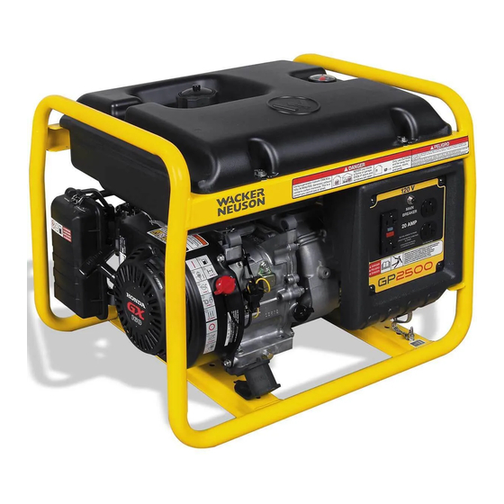
- Page 1 0160531en 1106 Generator GP 2500A OPERATOR’S MANUAL...
-
Page 2: Carbon Monoxide
DANGER CARBON MONOXIDE Using a generator indoors CAN KILL YOU IN MINUTES. Generator exhaust contains carbon monoxide (CO). This is a poison you cannot see or smell. If you can smell the generator exhaust, you are breathing CO. But even if you cannot smell the exhaust, you could be breathing CO. -
Page 3: Table Of Contents
Indoor Installation ................18 Generator Derating ................19 Grounding the Generator ..............20 Operating Heavy Loads ..............20 Use of Extension Cords ..............21 Control Panel—GP 2500A ..............22 Ground Fault Interrupt (GFI) ............... 23 5.10 Circuit Breaker ..................23 5.11 Before Starting ................... - Page 4 Table of Contents GP 2500A Maintenance Engine Maintenance ................26 Periodic Maintenance Schedule ............26 Engine Oil ....................27 Servicing Air Cleaner ................28 Spark Plug ...................29 Cleaning the Sediment Cup ..............30 Carburetor Adjustment ................31 Adjusting Engine Speed ..............32 Storage ....................32 6.10 Transport .....................33 6.11...
-
Page 5: Foreword
CALIFORNIA Proposition 65 Warning: Engine exhaust, some of its constituents, and certain vehicle components, contain or emit chemicals known to the State of WARNING California to cause cancer and birth defects or other reproductive harm. Foreword This manual provides information and procedures to safely operate and maintain this Wacker model. -
Page 6: California Evaporative Emission Control Warranty Statement
California Evaporative Emission Control Warranty Statement California Evaporative Emission Control Warranty Statement YOUR WARRANTY RIGHTS AND OBLIGATIONS The California Air Resources Board and Wacker Corporation, Inc. are pleased to explain the evaporative emission control system (EECS) warranty on your model year 2006 and later portable generator. In California, new portable generators must be designed, built and equipped to meet the State’s stringent anti-smog standards. - Page 7 California Evaporative Emission Control Warranty Statement OWNER’S WARRANTY RESPONSIBILITIES: As the portable generator owner, you are responsible for performance of the required maintenance listed in your owner’s manual. Wacker Corporation recommends that you retain all receipts covering maintenance on your portable generator, but Wacker Corporation cannot deny warranty solely for the lack of receipts.
-
Page 8: Safety Information
Safety Information GP 2500A Safety Information This manual contains DANGER, WARNING, CAUTION, and NOTE callouts which must be followed to reduce the possibility of personal injury, damage to the equipment, or improper service. This is the safety alert symbol. It is used to alert you to potential personal injury hazards. -
Page 9: Operating Safety
GP 2500A Safety Information Operating Safety BACKFEED FROM THE GENERATOR INTO THE PUBLIC POWER DISTRIBUTION SYSTEM CAN CAUSE SERIOUS INJURY OR DEATH TO UTILITY WORKERS! DANGER Improper connection of generator to a building's electrical system can allow electrical current from the generator to backfeed into utility lines. - Page 10 Safety Information GP 2500A 3.2.12 ALWAYS store the equipment properly when it is not being used. Equipment should be stored in a clean, dry location out of the reach of children. 3.2.13 ALWAYS position operate generator firm, noncombustible, level surface.
-
Page 11: Operator Safety While Using Internal Combustion Engines
GP 2500A Safety Information Operator Safety while using Internal Combustion Engines Internal combustion engines present special hazards during operation and fueling. Read and follow the warning instructions in the engine owner’s manual and the safety guidelines below. Failure to follow the DANGER warnings and safety guidelines could result in severe injury or death. -
Page 12: Service Safety
Safety Information GP 2500A Service Safety Poorly maintained equipment can become a safety hazard! In order for the equipment to operate safely and properly over a long period of time, periodic maintenance and occasional repairs are necessary. If WARNING the generator is experiencing problems or is being serviced, attach a “DO NOT START”... -
Page 13: Label Locations
GP 2500A Safety Information Label Locations wc_si000149gb.fm... -
Page 14: Safety And Operating Labels
Safety Information GP 2500A Safety and Operating Labels Wacker machines use international pictorial labels where needed. These labels are described below: Label Meaning DANGER! No sparks, flames or burning objects near machine. Shut off the engine before refueling. WARNING! Hot surface! DANGER! Asphyxiation hazard. - Page 15 GP 2500A Safety Information Label Meaning Electrical ground CAUTION! Use only clean, filtered gasoline fuel. Check the fuel level. Open the fuel flow valve. Close the choke. Turn the engine switch to the ON position. wc_si000149gb.fm...
- Page 16 Safety Information GP 2500A Label Meaning Pull the rewind starter. Open the choke. Turn the engine switch to "OFF". Close the fuel flow valve. Important Emissions Information This equipment meets California EVP emission regulations for small off-road engines. A nameplate listing the model number, item number, revision number, and serial number is attached to each unit.
-
Page 17: Technical Data
GP 2500A Technical Data Technical Data Generator Item No. GP 2500A 0620009 Generator Maximum Output 2500 Continuous Output 2250 Type Single voltage, single phase, Auto voltage regulator system AC Voltages Available volts phase 1ø Frequency Power Factor AC receptacles: 125V GFI duplex... -
Page 18: Engine
Technical Data GP 2500A Engine Item No. GP 2500A 0620009 Engine Engine Make Honda Engine Model GX 160 K1VX Rated Power kW (Hp) 4.1 (5.5) Spark Plug BPR6ES / W20EPR-U Electrode Gap mm (in.) 0.7–0.8 (0.028–0.031) Operating Speed (Max.) 3600... -
Page 19: Operation
GP 2500A Operation Operation Determining Power Requirements This generator is designed to operate single-phase, 60 Hz appliances running at 120 VAC. Check the nameplate or label provided on tools and appliances to make sure their power requirements match the power output of the generator. -
Page 20: Outdoor Installation
Operation GP 2500A Outdoor Installation Place the generator in an area where it will not be exposed to rain, snow, or direct sunlight. Make sure it is positioned on firm, level ground, so it will not slide or shift. Position the engine exhaust away from areas where people may be present. -
Page 21: Generator Derating
GP 2500A Operation Generator Derating All generators are subject to derating for altitude and temperature. Internal combustion engines, unless modified, run less efficiently at higher altitudes due to the reduction of air pressure. This translates into a lack of power and thus reduction in generator output. -
Page 22: Grounding The Generator
Operation GP 2500A Grounding the Generator See Graphic: wc_gr000544 A ground connection (a) is located on the generator frame. For proper operating safety, this ground terminal must be connected to a good ground source. This ground connection must comply with National Electrical Code standards, and state and local regulations. -
Page 23: Use Of Extension Cords
GP 2500A Operation Use of Extension Cords When a long extension cord is used to connect an appliance or tool to the generator, a voltage loss occurs—the longer the cord, the greater the voltage loss. This results in less voltage being supplied to the appliance or tool and increases the amount of current draw or reduces performance. -
Page 24: Control Panel-Gp 2500A
Operation GP 2500A Control Panel—GP 2500A See Graphic: wc_gr002324 Ref. Description Ref. Description GFI duplex receptacle—120V GFI test button Circuit breaker—20 Amp. GFI reset button Duplex receptacle—120V wc_tx000447gb.fm... -
Page 25: Ground Fault Interrupt (Gfi)
GP 2500A Operation Ground Fault Interrupt (GFI) See Graphic: wc_gr002324 The 120V, 20 Amp receptacle (a) is equipped with a ground fault circuit interrupt (GFI). The GFI shuts off the power to the receptacle when a ground fault occurs in the generator or to a piece of equipment attached to the generator. -
Page 26: Before Starting
Operation GP 2500A 5.11 Before Starting 5.11.1 Read and understand the safety and operating labels and instructions at the beginning of this manual 5.11.2 Inspect the generator for any signs of damage which may affect operation or pose a safety hazard. -
Page 27: To Start
GP 2500A Operation 5.12 To Start See Graphic: wc_gr002818 5.12.1 Disconnect all loads from the generator. 5.12.2 Open the fuel valve (a1). Note: If the engine is cold, move the choke lever to the closed position (b2). If the engine is hot, set the choke to the open position (b1). -
Page 28: Maintenance
Maintenance GP 2500A Maintenance Engine Maintenance The chart below lists basic machine and engine maintenance. Refer to engine manufacturer’s Operator’s Manual additional information on engine maintenance. Periodic Maintenance Schedule Daily After Every Every Every before first starting 20 hrs. hrs. -
Page 29: Engine Oil
GP 2500A Maintenance Engine Oil See Graphic: wc_gr000022 6.3.1 Drain the oil while the engine is still warm. 6.3.2 Remove the oil filler plug (a) and the drain plug (b) to drain the oil. Note: In the interests of environmental protection, place a plastic sheet and a container under the machine to collect any liquid that drains off. -
Page 30: Servicing Air Cleaner
Maintenance GP 2500A Servicing Air Cleaner See Graphic: wc_gr002815 Service the air cleaner frequently to prevent carburetor malfunction. CAUTION: NEVER run the engine without the air cleaner. Severe engine damage will occur. NEVER use gasoline or other types of low flash-point solvents for cleaning the air cleaner. -
Page 31: Spark Plug
GP 2500A Maintenance Spark Plug See Graphic: wc_gr000028 Clean or replace the spark plug as needed to ensure proper operation. Refer to the engine owner’s manual. The muffler becomes very hot during operation and remains hot for a while after stopping the engine. Do not touch the muffler while it is hot. -
Page 32: Cleaning The Sediment Cup
Maintenance GP 2500A Cleaning the Sediment Cup See Graphic: wc_gr000029 6.6.1 Turn the fuel valve off. 6.6.2 Remove the sediment cup (a) and the O-ring (b). 6.6.3 Wash both thoroughly in a nonflammable solvent. Dry and reinstall them. 6.6.4 Turn the fuel valve on and check for leaks. -
Page 33: Carburetor Adjustment
GP 2500A Maintenance Carburetor Adjustment See Graphic: wc_gr000032 6.7.1 Start the engine and allow it to warm up to operating temperature. 6.7.2 Set the pilot screw (a) two turns out. See Note. 6.7.3 With the engine idling, turn the pilot screw (a) in or out to the setting that produces the highest rpm. -
Page 34: Adjusting Engine Speed
Maintenance GP 2500A Adjusting Engine Speed See Graphic: wc_gr000032 Generators require a fixed engine speed to maintain the correct voltage. Engine speed is controlled by a governor which automatically adjusts to varying loads on the engine to maintain a constant speed. -
Page 35: Transport
GP 2500A Maintenance 6.10 Transport Let the engine cool before transporting the generator or storing indoors, to avoid burns or fire hazards. WARNING When transporting the generator: 6.10.1 Turn the engine fuel valve to the OFF position. 6.10.2 Position the generator level to prevent fuel from spilling. -
Page 36: Wire Colors
Maintenance GP 2500A 6.12 Wire Colors Wire Colors Black Yellow Orange Green Brown Purple Blue Violet Clear Shield Pink White Gray Light blue 6.13 Wiring Schematic See Graphic: wc_gr002325 Ref. Description Ref. Description Ref. Description Generator Control Box Engine Ref. - Page 37 GP 2500A Maintenance wc_tx000448gb.fm...
- Page 38 Maintenance GP 2500A Notes wc_tx000448gb.fm...
- Page 40 Wacker Construction Equipment AG · Preußenstraße 41 · D-80809 München · Tel.: +49-(0)89-3 54 02 - 0 · Fax: +49 - (0)89-3 54 02-3 90 Wacker Corporation · P.O. Box 9007 · Menomonee Falls, WI 53052-9007 · Tel. : (262) 255-0500 · Fax: (262) 255-0550 · Tel. : (800) 770-0957 Wacker Asia Pacific Operations ·...
Need help?
Do you have a question about the GP 2500A and is the answer not in the manual?
Questions and answers