
Related Manuals for Wacker Neuson G 70


Summary of Contents for Wacker Neuson G 70
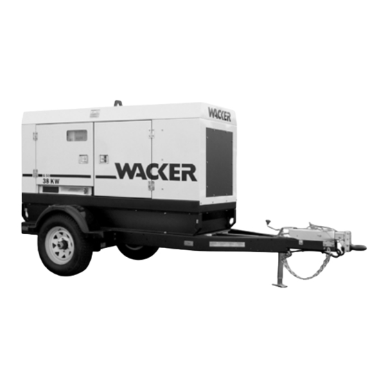
- Page 1 0162089en 1107 Mobile Generator G 50 G 70 G 85 OPERATOR’S MANUAL...
-
Page 3: Table Of Contents
G 50/G 70/G 85 Table of Contents Foreword Safety Information Operating Safety .................. 8 Service Safety ..................10 Operator Safety while using Internal Combustion Engines ....11 Towing Safety ..................12 Reporting Trailer Safety Defects ............13 Label Location ..................14 Safety and Operating Labels .............. - Page 4 Generator and Receptacle Wiring ............54 4.11 Trailer Wiring ..................60 4.12 G 50/G 70 Engine Wiring ..............62 4.13 G 85 & G 70 w/ECU Engine Wiring .............70 Factory-Installed Options Block Heater ..................74 Fuel/Water Separator ................75 Electronic Governor ................76 LCD Strip Heater .................77 Low Coolant Shutdown ...............78...
-
Page 5: Foreword
Foreword Foreword This manual provides information and procedures to safely operate and maintain this Wacker model. For your own safety and protection from injury, carefully read, understand and observe the safety instructions described in this manual. Keep this manual or a copy of it with the machine. If you lose this manual or need an additional copy, please contact Wacker Corporation. -
Page 6: Safety Information
Safety Information G 50/G 70/G 85 Safety Information This manual contains DANGER, WARNING, CAUTION, NOTICE and NOTE callouts which must be followed to reduce the possibility of personal injury, damage to the equipment, or improper service. This is the safety alert symbol. It is used to alert you to potential personal injury hazards. - Page 7 This machine is built with user safety in mind; however, like any electrical device it can present serious hazards if improperly operated and serviced. Follow instructions carefully! Should questions arise during operation or service of this equipment, contact Wacker Corporation. wc_si000158gb.fm...
-
Page 8: Operating Safety
Safety Information G 50/G 70/G 85 Operating Safety Familiarity and proper training are required for the safe operation of the machine. Machines operated improperly or by untrained personnel can be dangerous. Read the operating instructions contained in both WARNING this manual and the Engine Manual and familiarize yourself with the location and proper use of all controls. - Page 9 G 50/G 70/G 85 Safety Information 2.1.17 ALWAYS keep the area immediately surrounding and underneath the machine clean, neat, and free of debris and combustible materials. Make sure that the area overhead is clear of debris that could fall onto or into the machine or exhaust compartment.
-
Page 10: Service Safety
Safety Information G 50/G 70/G 85 Service Safety A poorly maintained machine can become a safety hazard! In order for the machine to operate safely and properly over a long period of time, periodic maintenance and occasional repairs are necessary. -
Page 11: Operator Safety While Using Internal Combustion Engines
G 50/G 70/G 85 Safety Information 2.2.11 ALWAYS remain aware of moving parts and keep hands, feet, and loose clothing away from the moving parts of the machine. 2.2.12 ALWAYS replace all guards, fasten doors and make sure all safety devices operate properly after making repairs or servicing the equipment. -
Page 12: Towing Safety
Safety Information G 50/G 70/G 85 Towing Safety Towing a large trailer requires special care. Both the trailer and vehicle must be in good condition and securely fastened to each other to reduce the possibility of an accident. WARNING 2.4.1 ALWAYS check that the hitch and coupling on the vehicle are rated equal to, or greater than, the trailer's “gross vehicle weight rating”... -
Page 13: Reporting Trailer Safety Defects
G 50/G 70/G 85 Safety Information Reporting Trailer Safety Defects If you believe your trailer has a defect which could cause a crash or could cause injury or death, you should immediately inform the National Highway Traffic Safety Administration (NHTSA) in addition to notifying Wacker Corporation. -
Page 14: Label Location
Safety Information G 50/G 70/G 85 Label Location wc_si000158gb.fm... - Page 15 G 50/G 70/G 85 Safety Information wc_si000158gb.fm...
-
Page 16: Safety And Operating Labels
Safety Information G 50/G 70/G 85 Safety and Operating Labels Ref. Label Meaning TOWING INSTRUCTIONS ABSCHLEPPINSTRUKTIONEN INSTRUCCIONES DE REMOLQUE INSTRUCTIONS DE REMORQUAGE 1. LEA EL MANUAL DEL OPERARIO. 1. LIRE LA NOTICE D'EMPLOI. 1. READ OPERATOR'S MANUAL. 1. BETRIEBSVORSCHRIFT LESEN. - Page 17 G 50/G 70/G 85 Safety Information Ref. Label Meaning DANGER! Asphyxiation hazard. Read the Opera- tor’s Manual for instructions. No sparks, flames, or burning objects near machine. Stop the engine before adding fuel. Use only diesel fuel. Tie-down point. WARNING! To prevent hearing loss, wear hearing protection.
- Page 18 Safety Information G 50/G 70/G 85 Ref. Label Meaning Operator’s Manual must be stored on machine. Replacement Operator’s Manual can be ordered through your local Wacker distributor. DANGER! Electric shock will cause serious injury or death. Danger of asphyxiation! wc_si000158gb.fm...
- Page 19 G 50/G 70/G 85 Safety Information Ref. Label Meaning WARNING! Generator can automatically start which can cause serious injury. Disconnect battery before servicing. WARNING! Read and understand the supplied Operator’s Manual before operating the machine. Failure to do so increases the risk of injury to yourself or others.
- Page 20 Safety Information G 50/G 70/G 85 Ref. Label Meaning WARNING! Disconnect battery before servicing. W A R N I N G W A R N U N G Read the Operator's Manual. A D V E R T E N C I A...
- Page 21 Read the operator's manual for machine information. 1 - Controller 2 - Not used 3 - Not used 4 - Not used WARNING! Electric shock at cooling fins. G 50 / G 70 / G 85 Generator and Receptacle Wiring wc_si000158gb.fm...
- Page 22 Safety Information G 50/G 70/G 85 Ref. Label Meaning G 50 / G 70 - Engine Wiring G 70 w/ECU & G 85 - Engine Wiring WARNING! Hot surface! A nameplate listing the model number, item number, revision number, and serial number is attached to each unit.
- Page 23 G 50/G 70/G 85 Safety Information Ref. Label Meaning CAUTION: Do not use battery disconnect CAUTION DO NOT USE THE BATTERY DISCONNECT SWITCH WHILE ENGINE IS DO NOT USE THE BATTERY DISCONNECT SWITCH WHILE ENGINE IS RUNNING. DAMAGE TO THE ELECTRICAL COMPONENTS MAY OCCUR.
-
Page 24: Operation
Operation G 50/G 70/G 85 Operation Control Panels wc_tx000483gb.fm... - Page 25 G 50/G 70/G 85 Operation Ref. Description Ref. Description Main Circuit Breaker Twist-Lock Receptacle (120/240 VAC, 50Amp) - two Voltage Adjustment Rheostat Twist-Lock Receptacle (120/240 VAC, 30 Amp) Shutdown LED GFI Receptacle (120 VAC, 20 Amp) - two Pre-alarm LED...
-
Page 26: Generator Monitoring
Operation G 50/G 70/G 85 Generator Monitoring Generator information is displayed on the top line of the LCD panel and is scrolled continuously while the generator is operating, to show the voltage, amperage and frequency of each phase. Note: To prevent the display from scrolling, press the ENG HRS switch down. -
Page 27: Engine Monitoring
Sample display of engine hours. RUNNING HOURS 135.2 Sample display of periodic maintenance timer. TIME TO SERVICE 180.2 hrs. G 85 & G 70 w/ECU only Sample display showing Engine Diagnostic Trouble Codes. SPN.FMI 100.01 SPN = Suspect Parameter Number FMI = Failure Mode Identifier. -
Page 28: Engine Shutdown Faults
Indicates that the emergency stop button has been depressed. This display will remain on EMERGENCY until the emergency stop button is pulled back STOP out. G 70 w/ECU & G 85 only Sample display showing Engine Diagnostic Trouble Codes. SPN.FMI 100.01 SPN = Suspect Parameter Number FMI = Failure Mode Identifier. -
Page 29: Current Overload Fault
G 50/G 70/G 85 Operation Normal operating pressure is between 40–80 psi. If oil pressure drops below 15 psi, the engine will automatically shut down. LOW OIL LEVEL For machines with the Low-Coolant Shutdown Option only. This fault will be displayed when... -
Page 30: Voltage Selector Switch
Operation G 50/G 70/G 85 Voltage Selector Switch See Graphic: wc_gr001682 The voltage selector switch is located in a separate enclosure on the generator on the opposite side of the machine. The selector switch is a three-position switch which mechanically changes the connections between the generator output leads and the terminal lugs on the generator. -
Page 31: Emergency Stop Switch
G 50/G 70/G 85 Operation Emergency Stop Switch See Graphic: wc_gr001677 The emergency stop switch (p) is the red button located below the receptacle panel and can be accessed with the panel doors closed. Activate the emergency stop switch by pushing the red button in. -
Page 32: Main Line Circuit Breaker
Operation G 50/G 70/G 85 Main Line Circuit Breaker See Graphic: wc_gr002611 The main line circuit breaker (a) is located on the control panel. In the “off” position, this breaker interrupts power from the selector switch to the terminal lugs at the bottom of the generator panel. -
Page 33: Engine Start Switch
G 50/G 70/G 85 Operation 3.10 Engine Start Switch See Graphic: wc_gr002611 The engine start switch (f) is a three-position switch: “REMOTE START”, off “O”, and “START/RUN”. The “REMOTE START” position is the normal setting used when using the generator as a back-up power supply connected to a remote switch. -
Page 34: Connection Lugs
Operation G 50/G 70/G 85 3.13 Connection Lugs See Graphic: wc_gr002611 The customer connection lugs (r) are located on left at the bottom of the panel behind a hinged door. The lugs provide connection points for attachment of outside loads. -
Page 35: Ground Connection
G 50/G 70/G 85 Operation 3.14 Ground Connection See Graphic: wc_gr002611 A ground connection (s) is located next to the terminal lugs. The unit must have this ground lug connected to a good earthen ground for proper operating safety in compliance with NEC and local standards. -
Page 36: Terminal Connections
Operation G 50/G 70/G 85 3.18 Terminal Connections ALL CONNECTIONS TO THE TERMINALS MUST BE MADE BY A TRAINED ELECTRICIAN. BACKFEED FROM THE GENERATOR INTO THE UTILITY’S DISTRIBUTION SYSTEM CAN CAUSE A SERIOUS INJURY OR DEATH TO UTILITY WORKERS! DANGER Improper connection of generator to a building’s electrical system can... -
Page 37: Before Starting
G 50/G 70/G 85 Operation 3.19 Before Starting Before putting the generator into service, review each item on the following checklist. Because generators are often run for long periods of time unattended, it is important to make sure that the unit is set up properly to reduce possible problems. -
Page 38: Manual Start-Up
Operation G 50/G 70/G 85 3.20 Manual Start-up See Graphic: wc_gr001682, wc_gr001677, wc_gr002611 Before starting the generator set, thoroughly review the pre-start-up checklist in the previous section. Proceed with generator start-up only after checking each item in that section. Thoroughly read and make sure you understand the engine Operator’s Manual supplied with the generator. - Page 39 G 50/G 70/G 85 Operation 3.20.7 After engine starts, allow it to warm up for a few minutes and check readouts on LCD panel. The “TIME TO SERVICE” interval will be displayed. Make sure battery charging system, oil pressure and engine temperature readings are within normal ranges.
-
Page 40: Running The Generator
Operation G 50/G 70/G 85 3.21 Running the Generator See Graphic: wc_gr002611 Leave the Engine Start Switch (f) in the “START/RUN” position while the generator is operating. If the generator was started using a remote switch, leave Engine Start Switch in the “REMOTE START” position. - Page 41 G 50/G 70/G 85 Operation (2,1) (2,4) (2,75) (3,0) (3,3) (3,6) (4,0) (4,3) (4,6) (4,9) (5,2) (5,5) Altitude x 1000 Feet wc_gr001227 wc_tx000483gb.fm...
-
Page 42: Shutting Down Generator
Operation G 50/G 70/G 85 3.23 Shutting Down Generator Check with other personnel on the jobsite and let them know that power is being turned off. Make sure that the power shutdown will not create any hazards by turning off devices such as pumps, heaters, or lights that may need to be kept on. -
Page 43: Automatic/Remote Start-Up
G 50/G 70/G 85 Operation 3.28 Automatic/Remote Start-up See Graphic: wc_gr002611 In the “REMOTE START” position the generator can be started remotely, either through a transfer switch or some other type of remote start switch. “REMOTE START” is the normal setting when using the generator as a standby power supply. -
Page 44: Remote/Transfer Switch
Operation G 50/G 70/G 85 3.29 Remote/Transfer Switch See Graphic: wc_gr002611 When the generator is used as a standby power supply, it must be equipped with a device which isolates it from the utility’s distribution system. DANGER Failure to isolate the generator from the utility’s electrical... -
Page 45: Towing
G 50/G 70/G 85 Operation 3.30 Towing See Graphic: wc_gr000510 The generator trailer is equipped with brakes, lights, and coupler connection. Before towing the generator, perform the following: 3.30.1 Check that the towing vehicle and hitch have a rating equal to or greater than the GVWR. - Page 46 Operation G 50/G 70/G 85 w c _ g r 0 0 0 5 1 0 wc_tx000483gb.fm...
-
Page 47: Maintenance
G 50/G 70/G 85 Maintenance Maintenance Periodic Maintenance Schedule The Periodic Maintenance Schedule below lists basic maintenance intervals for the engine and generator. For detailed maintenance procedures on the engine, refer to the engine Operator's Manual. Daily 50 Hrs 250 Hrs 600 Hrs... -
Page 48: New Machines
Maintenance G 50/G 70/G 85 New Machines 4.2.1 Run generator at least 60–100% of continuous load for the first 100 hours. 4.2.2 Change engine oil and replace oil filter after the first 50 hours. Resetting the Periodic Maintenance Timer After maintenance has been performed on the generator, it is necessary to reset the periodic maintenance timer. -
Page 49: Air Cleaner
G 50/G 70/G 85 Maintenance Air Cleaner See Graphic: wc_gr000511 Replace the air filter cartridge when yellow indicator of the engine air filter gauge reaches the red line. The air cleaner assembly contains a one-piece single element air filter cartridge (c). -
Page 50: Engine Lubrication
Maintenance G 50/G 70/G 85 Engine Lubrication Check engine oil daily before starting engine. DO NOT operate engine if oil level is below ADD mark on dipstick. Always keep oil level within the crosshatch pattern or “full” mark on dipstick. -
Page 51: Engine Coolant
G 50/G 70/G 85 Maintenance Engine Coolant Check the coolant level of the radiator with the engine cold. After initial filling of radiator to 3/4" below bottom of filler neck, maintain proper level in overflow bottle daily. NEVER remove radiator cap or drain plug while engine is hot! Pressurized coolant can cause serious burns. -
Page 52: Troubleshooting Automatic Shutdown
Most of these diagnostics deal with the engine. The generator, however, can also cause problems. Consult a qualified electrician or your nearest WACKER Dealer for possible causes of generator problems. For SPN.FMI Diagnostic Codes, contact WACKER or John Deere service departments. -
Page 53: Wire Colors
G 50/G 70/G 85 Maintenance Overspeed or Underspeed Shutdown Restart engine and read the AC frequency meter. Meter should read 60 Hz under no-load condition. Overcrank Shutdown 4.8.1 Check fuel level. 4.8.2 Check for proper operation of fuel pump. 4.8.3 If engine still does not start, refer to engine manufacturer’s Operator’s... -
Page 54: Generator And Receptacle Wiring
Maintenance G 50/G 70/G 85 4.10 Generator and Receptacle Wiring Revision Revision Revision Graphic: Graphic: Graphic: 0009366 123 & higher wc_gr004692 106–122 wc_gr003171 105 & lower wc_gr002614 0009367 124 & higher wc_gr004692 106–123 wc_gr003171 105 & lower wc_gr002614 0009369 124 & higher wc_gr004692 106–123... - Page 55 G 50/G 70/G 85 Maintenance wc_tx000484gb.fm...
- Page 56 Maintenance G 50/G 70/G 85 Revision Revision Revision Graphic: Graphic: Graphic: 0009366 123 & higher wc_gr004692 106–122 wc_gr003171 105 & lower wc_gr002614 0009367 124 & higher wc_gr004692 106–123 wc_gr003171 105 & lower wc_gr002614 0009369 124 & higher wc_gr004692 106–123 wc_gr003171 105 &...
- Page 57 G 50/G 70/G 85 Maintenance wc_tx000484gb.fm...
- Page 58 Maintenance G 50/G 70/G 85 Revision Revision Revision Graphic: Graphic: Graphic: 0009366 123 & higher wc_gr004692 106–122 wc_gr003171 105 & lower wc_gr002614 0009367 124 & higher wc_gr004692 106–123 wc_gr003171 105 & lower wc_gr002614 0009369 124 & higher wc_gr004692 106–123 wc_gr003171 105 &...
- Page 59 G 50/G 70/G 85 Maintenance wc_tx000484gb.fm...
-
Page 60: Trailer Wiring
Maintenance G 50/G 70/G 85 4.11 Trailer Wiring Ref. Description Front right side amber light Front left side amber light Trailer plug Battery Brake solenoid Right rear taillight License plate holder lights Left rear taillight Rear right side red light Rear left side red light Ref. - Page 61 G 50/G 70/G 85 Maintenance Standard and Hydraulic Brakes Electric Brakes Br W – Br W Br W wc_gr000523 wc_tx000484gb.fm...
-
Page 62: G 50/G 70 Engine Wiring
Maintenance G 50/G 70/G 85 4.12 G 50/G 70 Engine Wiring Revision Revision Rev. Revision Graphic: Graphic: Graphic: Graphic: 0009366 123 & higher wc_gr004613 109-122 wc_gr003218 wc_gr003172 107 & lower wc_gr002615 0009367 124 & higher wc_gr004613 110-123 wc_gr003218 wc_gr003172 108 & lower... - Page 63 G 50/G 70/G 85 Maintenance G 50/G 70 Engine Wiring wc_tx000484gb.fm...
- Page 64 Maintenance G 50/G 70/G 85 Revision Revision Rev. Revision Graphic: Graphic: Graphic: Graphic: 0009366 123 & higher wc_gr004613 109-122 wc_gr003218 wc_gr003172 107 & lower wc_gr002615 0009367 124 & higher wc_gr004613 110-123 wc_gr003218 wc_gr003172 108 & lower wc_gr002615 0009467 131 & higher...
- Page 65 G 50/G 70/G 85 Maintenance G 50/G 70 Engine Wiring wc_tx000484gb.fm...
- Page 66 Maintenance G 50/G 70/G 85 Revision Revision Rev. Revision Graphic: Graphic: Graphic: Graphic: 0009366 123 & higher wc_gr004613 109-122 wc_gr003218 wc_gr003172 107 & lower wc_gr002615 0009367 124 & higher wc_gr004613 110-123 wc_gr003218 wc_gr003172 108 & lower wc_gr002615 0009467 131 & higher...
- Page 67 G 50/G 70/G 85 Maintenance G 50/G 70 Engine Wiring wc_tx000484gb.fm...
- Page 68 Maintenance G 50/G 70/G 85 Revision Revision Rev. Revision Graphic: Graphic: Graphic: Graphic: 0009366 123 & higher wc_gr004613 109-122 wc_gr003218 wc_gr003172 107 & lower wc_gr002615 0009367 124 & higher wc_gr004613 110-123 wc_gr003218 wc_gr003172 108 & lower wc_gr002615 0009467 131 & higher...
- Page 69 G 50/G 70/G 85 Maintenance G 50/G 70 Engine Wiring wc_tx000484gb.fm...
-
Page 70: G 85 & G 70 W/Ecu Engine Wiring
Maintenance G 50/G 70/G 85 4.13 G 85 & G 70 w/ECU Engine Wiring Revision See Graphic: Revision See Graphic: 0009369 124 & higher wc_gr004614 123 & lower wc_gr002616 0009459 133 & higher wc_gr004614 132 & lower wc_gr002616 0620003 129 & higher wc_gr004614 128 &... - Page 71 G 50/G 70/G 85 Maintenance G 85 & G 70 w/ECU Engine Wiring wc_tx000484gb.fm...
- Page 72 Maintenance G 50/G 70/G 85 Revision See Graphic: Revision See Graphic: 0009369 124 & higher wc_gr004614 123 & lower wc_gr002616 0009459 133 & higher wc_gr004614 132 & lower wc_gr002616 0620003 129 & higher wc_gr004614 128 & lower wc_gr002616 0620350 wc_gr004614...
- Page 73 G 50/G 70/G 85 Maintenance wc_tx000484gb.fm...
-
Page 74: Factory-Installed Options
This machine may be equipped with one or more of the following factory-installed options. To verify if any of these options are installed on your machine, contact the WACKER Corporation at 1-800-770-0957. A nameplate listing the Model Number, Item Number, Revision, and Serial Number is attached to each unit. Please have this information available when contacting WACKER Corporation. -
Page 75: Fuel/Water Separator
Mobile Generators Factory-Installed Options Fuel/Water Separator See Graphic: wc_gr001705 The fuel/water separator separates water from the fuel on models with Isuzu engines. Empty the separator water bowl (a) as needed by opening the water bowl drain (b). The separator element should be changed each time the fuel filter is changed—approximately every 600 hours of operation. -
Page 76: Electronic Governor
Factory-Installed Options Mobile Generators Electronic Governor See Graphic: wc_gr001714, wc_gr001715, wc_gr001716, wc_gr001717 The electronic governor option consists of an electronic module (a or b) and an electronic actuator (c or d). The module senses rotation of the flywheel, then sends a signal to the electronic actuator that governs the fuel injection system. -
Page 77: Lcd Strip Heater
Mobile Generators Factory-Installed Options LCD Strip Heater See Graphic: wc_gr001724, wc_gr001725 The LCD strip heater option includes a thermostat module (a) and a clear heater strip that is bonded to the LCD (b) of the ECM. The purpose of the strip heater is to prevent the LCD from being damaged by extremely cold temperatures. -
Page 78: Low Coolant Shutdown
Factory-Installed Options Mobile Generators Low Coolant Shutdown See Graphic: wc_gr001708 The low-coolant shutdown system consists of an electronic sensor that monitors coolant level. The sensor (a) is mounted to the radiator and wired into the ECM. The sensor probe (b) is submerged in radiator coolant. -
Page 79: Lube Level Maintainer
Mobile Generators Factory-Installed Options Lube Level Maintainer See Graphic: wc_gr001711, wc_gr001712, wc_gr001713 The lube level maintainer system protects the engine from low oil levels by providing an additional 6-quart oil reservoir. Oil from the reservoir is gravity-fed from the oil reservoir (a) through the control valve (b) and into the engine oil pan as needed. -
Page 80: Temperature-Activated Shutters
Factory-Installed Options Mobile Generators Temperature-Activated Shutters See Graphic: wc_gr001706, wc_gr001707 The shutters (a) are mounted to the top of the generator enclosure. The shutters are designed to keep the engine compartment warm, thus increasing engine temperature during cold weather operation. The shutters are activated through a wax-pellet actuator (b) that is connected to the generator's cooling system. - Page 81 Mobile Generators Factory-Installed Options Notes: wc_tx000380gb.fm...
-
Page 82: Wiring Diagram
Factory-Installed Options Mobile Generators Wiring Diagram – wc_gr001868 Wire Colors Black Yellow Orange Green Brown Purple Blue Violet Clear Shield Pink White Gray Light blue wc_tx000380gb.fm... -
Page 83: Wiring Diagram Components
Mobile Generators Factory-Installed Options 5.10 Wiring Diagram Components See Graphic: wc_gr001868 Description Description Thermostat module Positive air shutoff solenoid actuator Terminal block Auxiliary relay terminals 1 Amp fuse Plug 1, engine sensor inputs Water level sensor Electronic control board Lube level maintainer low level LCD heater switch 30 Amp circuit breaker... -
Page 84: Cam-Lock
Factory-Installed Options Mobile Generators 5.11 Cam-Lock See Graphic: wc_gr002584 A second optional outlet panel features cam-lock connectors (u) for easy tool changes. The door is equipped with an interlock switch (q). When the door is opened this switch automatically trips the main circuit breaker. -
Page 85: Table Of Contents
Mobile Generators Factory-Installed Options 5.12 Containment System See Graphic: wc_gr002647 Overspills and leaks are captured in the containment system. The containment system holds over 110% of the fluid contained in the machine. The containment system should be checked every 50 hours or 2 weeks and drained when necessary. -
Page 86: Technical Data
Technical Data G50 /G 70/G 85 Technical Data Engine Data Item Number: G 50 G 70 G 85 0009366 0009367 0009369 G 70 0009467 0009468 0009459 0620350 0620001 0620002 0620003 0620352 Rev. Rev. Rev. 112 & lower 113 & lower 114 &... - Page 87 G50 /G 70/G 85 Technical Data Item Number: G 50 G 70 G 85 0620001 0620002 G 70 0620003 Rev. Rev. 0620351 Rev. 113 & above 114 & above 115 & above Engine Engine make / John Deere / 4.5L...
-
Page 88: Generator Data
Technical Data G50 /G 70/G 85 Generator Data Item Number: G 50 G 70 G 70 G 85 0009366 0009367 0620350 0009369 0009467 0009468 0620351 0009459 0620001 0620002 0620352 0620003 Generator Make/Type Mecc Alte / Brushless Model ECO32-3S/4 ECO32-2L/4 ECO32-3L/4... -
Page 89: Trailer And Skid Data
G50 /G 70/G 85 Technical Data Trailer and Skid Data Item G 50 G 50 G 70 G 70 G 70 G 70 G 85 G 85 Number: 0009366 0009467 0009367 0009468 0620350 0620351 0009369 0009459 0620001 0620002 0620352 0620003... -
Page 90: Dimensions
Technical Data G50 /G 70/G 85 Dimensions mm (inches) - Page 92 Wacker Corporation · P.O. Box 9007 · Menomonee Falls, WI 53052-9007 · Tel. : (262) 255-0500 · Fax: (262) 255-0550 · Tel. : (800) 770-0957 Wacker Asia Pacific Operations · Skyline Tower, Suite 2303, 23/F · 39 Wang Kwong Road, Kowloon Bay, Hong Kong · Tel. +852 2406 60 32 · Fax: +852 2406 60 21...
Need help?
Do you have a question about the G 70 and is the answer not in the manual?
Questions and answers