
Related Manuals for SystemAir Topvex SF02-S12


Summary of Contents for SystemAir Topvex SF02-S12
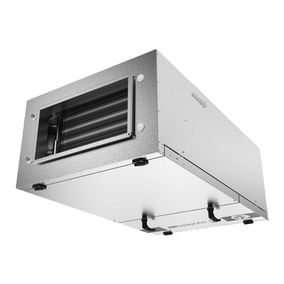
- Page 1 Topvex SF02-S12 Air Handling Unit Operation and Maintenance Instructions Document in original language | 130323 · A002...
- Page 2 © Copyright Systemair AB All rights reserved E&OE Systemair AB reserves the rights to alter their products without notice. This also applies to products already ordered, as long as it does not affect the previously agreed specifications. 130323 | A002...
-
Page 3: Table Of Contents
Contents Warnings............1 Product description..........2 Internal components .......2 Description internal components....2 2.2.1 Fan .........2 2.2.2 Supply air filter ......2 2.2.3 Pressure guard filters ....2 2.2.4 Temperature sensor....2 Heating battery........3 2.3.1 Water heating battery ....3 2.3.2 Electrical heater ......3 Electrical connection box, components..........4 Interface description ........4 Control panel.........4... -
Page 5: Warnings
Warnings | Warnings The following admonitions will be presented in the different sections of the document: Danger • Indicates a potentially or imminently hazardous situation which, if not avoided, could result in death or serious injury. Warning • Indicates a potentially hazardous situation that may result in minor or moderate injuries. Caution •... -
Page 6: Product Description
| Product description Product description Internal components Filter, supply air Fan, supply air Heater, electrical or water Electrical connection box Pressure guard filter Air flow sensor (only EL units) Outdoor air sensor Duct connection, outdoor air Duct connection, supply air Description internal components 2.2.1 The fan has external rotor motors of EC type which are steplessly controlled. -
Page 7: Heating Battery
Product description | Heating battery Warning • Although the mains power supply to the unit has been disconnected there is still risk for injury due to rotating parts that have not come to a complete standstill. • Beware of sharp edges during maintenance. Use protective clothing. •... -
Page 8: Electrical Connection Box, Components
| Interface description Electrical connection box, components Danger • Make sure that the mains power supply to the unit is disconnected before performing any maintenance or electrical work! • All electrical connections must be carried out by an authorized installer and in accordance with local rules and regulations. -
Page 9: Operating The Control Panel
Interface description | 3.1.1 Operating the control panel Fig. 2 The control panel Position Explanation Alarm button: Gives access to the alarm list. Alarm LED: Indicates alarm by flashing red light. Write LED: Indicates by flashing yellow light that parameters can be set or changed. OK button: Press this button to be able to change or set parameters whenever possible. -
Page 10: Commissioning
| Commissioning Commissioning Before starting the system When the installation is finished, check that: • The unit is installed in accordance with the installation instructions • The unit is correctly wired • Mufflers are installed and that the duct system is correctly connected to the unit •... - Page 11 To enter Service level use code 2222 in the “Access rights” menu. For operator level use code 1111. To enter Administrator level use code 3333 in the “Configuration menu”. Note: To perform more advanced settings please see the separate “General Commissioning Record” on www. systemair.com, online catalogue 130323 | A002...
-
Page 12: Menu Overview
| Commissioning Menu overview Below menu overview shows both the Operator, Service and Administrator level. The overview of the parts unique to the levels in below table are marked with different background color. Note: See Corrigo manual-Ventilation application for more information and additional configuration alternatives. To logon to Operator To logon to Service To logon to... - Page 13 Commissioning | Main menu item Sub-menu item 1 Sub-menu item 2 Explanations →DI Status of the Digital inputs. →UI Status of Universal Analogue inputs or Universal Digital inputs. →AO Status of the Analogue outputs. →DO Status of the Digital outputs. →Temperature Outd temp: ºC Actual outdoor air temperature.
- Page 14 | Commissioning Main menu item Sub-menu item 1 Sub-menu item 2 Explanations → Time settings → Time/Date Set correct time and date. Set 00:00 - 24:00 for continuous running. Setting 00:00 - 00:00 inactivates the period (stops the unit). Normal speed overrides Reduced speed i.e.
- Page 15 Commissioning | Main menu item Sub-menu item 1 Sub-menu item 2 Explanations → Manual/Auto In this menu the running mode of all the configured output signals and a number of control functions can be manually controlled. The supply air controller's output signal can be manually set (Manual/Auto) to any value between 0 and 100%.
- Page 16 | Commissioning Main menu item Sub-menu item 1 Sub-menu item 2 Explanations Extra sequence Y5 Set the Extra sequence to Auto, Auto Manual or Off Manual set: 0.0 Not used in default setting. Motor control1 Motor control Auto Note: Motor control2 Auto See Corrigo manual- Ventilation application for...
- Page 17 Commissioning | Main menu item Sub-menu item 1 Sub-menu item 2 Explanations → Alarm settings → Alarm limits Set the alarm limits and allowed deviations for the different functions → Alarm delays Set the alarm delays and allowed deviation delays for the different functions →...
- Page 18 | Commissioning Main menu item Sub-menu item 1 Sub-menu item 2 Explanations → Free cooling Free cool active: No Set free cooling active toYes or No. Outd. temp Set the lower outdoor day temperature limit for the activation activation 22°C of the free cooling function.
- Page 19 Commissioning | Main menu item Sub-menu item 1 Sub-menu item 2 Explanations → CO2/VOC Control In applications with varying CO2/VOC active occupancy the fan speeds can be Never controlled by the air quality as Type: Fan measured by a CO2/VOC-sensor. Min.
-
Page 20: Temperature Control Possibilities
| Commissioning Main menu item Sub-menu item 1 Sub-menu item 2 Explanations → Alarm no(1–115): 1 Alarm settings Run Error Supply Air → Set functionality and adjust Function Port1 Communication Slave communication settings Slave, Expansion unit, Freq conv/ Press tran, External display, Exp and freq conv or Exp and ext display. -
Page 21: Free Cooling
Maintenance | Free cooling This function is used during the warm period to save energy by using cold outdoor air, e.g. during night time, to cool down the building. Note: The following is only valid if the free cooling function is set to Active in the program menu. In order for the free cooling function to work, a total of 3 temperature sensors (outdoor, supply and extract/ room) are required. -
Page 22: Changing Air Filters
Changing air filters The bag filter cannot be cleaned and must be changed when necessary. New filters can be ordered from Systemair. Op- eration time between filter changes depends on the air pollution at the installation site. A differential pressure switch indicates when it’s time to change the filters. -
Page 23: Checking The Fan
Maintenance | Checking the fan Even if the required maintenance, such as changing of filters is carried out, dust and grease may slowly build up inside the fan. This will reduce the efficiency. The fan may be cleaned with a cloth or a soft brush. Do not use water. White spirit can be used to remove accumula- tions which are otherwise difficult to remove. -
Page 24: Changing The Internal Battery
| Maintenance Changing the internal battery Note: This procedure requires knowledge of proper ESD protection; i.e. an earthed wristband must be used! When the alarm ”Internal Battery” is activated and the battery LED lights up red, the battery for backup of program memory and real-time clock has become too weak. -
Page 25: Troubleshooting
Troubleshooting | Troubleshooting Should problems occur, please check or correct the following before contacting your service representative. Always check if there are any alarms active in the control panel. 1. The fan do not start • Check that the fuses are not defect. •... -
Page 26: Alarms
230/400V 25 A 50Hz 2. Production order number 4016 W IP23 225kg 3. Consecutive number 16kW 16kW 4. Production date 5. Product code (product Serial. no: 1234/567891-0001/140214 specification) Systemair Sverige AB Industrivägen 3 SE-73930 Skinnskatteberg www.systemair.com Sweden 130323 | A002... - Page 27 130323 | A002...
- Page 28 Systemair Sverige AB Industrivägen 3 SE-739 30 Skinnskatteberg, Sweden Phone +46 222 440 00 Fax +46 222 440 99 www.systemair.com...
Need help?
Do you have a question about the Topvex SF02-S12 and is the answer not in the manual?
Questions and answers