
Related Manuals for DeDietrich DHW 160 SL


Summary of Contents for DeDietrich DHW 160 SL
- Page 1 Domestic hot water tank 160 SL Installation, User and Service Manual 300026901-001-C...
-
Page 2: Table Of Contents
Contents Introduction ....................4 Symbols used ............4 Abbreviations ............4 General ..............4 1.3.1 Manufacturer's liability ..........4 1.3.2 Installer's liability .............5 1.3.3 User's liability ............5 Homologations ............6 1.4.1 Certifications ............6 1.4.2 Directive 97/23/EC ..........6 1.4.3 Factory test .............6 Safety instructions and recommendations ..........7 Safety instructions ..........7 Recommendations ..........7 Technical description ................8... - Page 3 Contents Electrical connections ........18 4.7.1 Recommendations ..........18 4.7.2 Connecting the domestic hot water sensor ...18 4.7.3 Connecting the impressed current anode .....19 4.7.4 Description of the boiler's terminal block ....19 Filling the system ..........20 4.8.1 Filling the secondary DHW circuit ......20 4.8.2 Filling the primary boiler circuit ......21 Commissioning ..................22...
- Page 4 15/03/2012 - 300026901-001-C...
-
Page 5: Introduction
160 SL 1. Introduction Introduction Symbols used In these instructions, various danger levels are employed to draw the user's attention to particular information. In so doing, we wish to safeguard the user's safety, obviate hazards and guarantee correct operation of the appliance. DANGER Risk of a dangerous situation causing serious physical injury. -
Page 6: Installer's Liability
1. Introduction 160 SL In the interest of customers, we are continuously endeavouring to make improvements in product quality. All the specifications stated in this document are therefore subject to change without notice. Our liability as the manufacturer may not be invoked in the following cases: 4 Failure to abide by the instructions on using the appliance. -
Page 7: Homologations
160 SL 1. Introduction Homologations 1.4.1. Certifications This product complies to the requirements to the european directives and following standards: 4 2006/95/EC Low Voltage Directive. Reference Standard: EN 60.335.1. 4 2004/108/EC Electromagnetic Compatibility Directive. Reference Standards: EN 50.081.1, EN 50.082.1, EN 55.014 1.4.2. -
Page 8: Safety Instructions And Recommendations
2. Safety instructions and recommendations 160 SL Safety instructions and recommendations Safety instructions CAUTION Before any work, switch off the mains supply to the appliance. CAUTION In order to limit the risk of being scalded, the installation of a thermostatic mixing valve on the domestic hot water flow piping is compulsory. -
Page 9: Technical Description
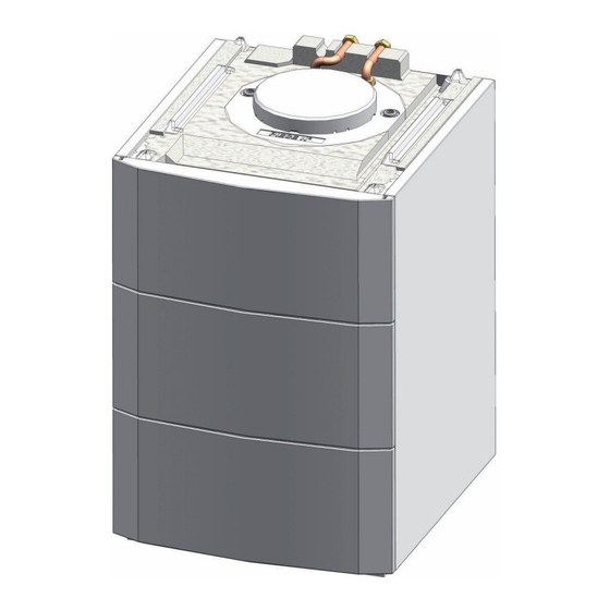
160 SL 3. Technical description Technical description General description The domestic hot water tank is delivered ready for connection to a boiler: 4 AGC 10/15 - AGC 15 - AGC 25 - AGC 35 4 GSCR 15 - GSCR 25 - GSCR 35 4 CALORA TOWER GAS 15S DE- CALORA TOWER GAS 25S DE- CALORA TOWER GAS 35S DE 4 CALORA TOWER OIL 18 - CALORA TOWER OIL 24 - CALORA... -
Page 10: Specifications Of The Dhw Sensor
3. Technical description 160 SL Performances related to the boiler type Gas fired floor-standing condensing boiler 10/15 kW 15 kW 25 kW 35 kW Power exchanged Flow per hour (∆T = 35°C) Draw-off capacity l/10 mm l/min 24.5 Specific flow (∆T = 30°C) : Primary flow rate (1) Depending on the country in which the boiler is installed (2) Domestic cold water inlet: 10 °C - Domestic hot water outlet: 45 °C - Primary circuit (heating water): 80 °C... -
Page 11: Installation
160 SL 4. Installation Installation Regulations governing installation CAUTION Installation of the appliance must be done by a qualified engineer in accordance with prevailing local and national regulations. CAUTION The installation must comply in all matters to the standards and rules which govern the work and interventions in individual and collective homes, and other constructions. -
Page 12: Choice Of The Location
4. Installation 160 SL Choice of the location 4.3.1. Data plate The rating plate must be accessible at all times. The rating plate identifies the product and provides the following information: 4 DHW calorifier type 4 Manufacturing date (Year - Week) 4 Serial number. -
Page 13: Main Dimensions
160 SL 4. Installation 4.3.3. Main dimensions M002331-B Domestic cold water inlet G 3/4" Secondary domestic hot water flow G 3/4" Location for recirculation loop G 3/4" (Option) Primary boiler flow G 3/4" Primary boiler return G 3/4" Drain cock 1/2" Location for DHW sensor Impressed current anode 15/03/2012 - 300026901-001-C... -
Page 14: Positioning The Appliance
4. Installation 160 SL Positioning the appliance CAUTION Have 2 people on hand. Handle the appliance with gloves. 1. Remove the packaging from the DHW tank, leaving the tank on the pallet used for transport. 2. Remove the protective packaging. M002347-B 3. - Page 15 160 SL 4. Installation 4. Open the front panel by pulling forwards until it reaches the safety catch. 5. Insert a screwdriver to unclip the springs at both ends. 6. Remove the front panel. M002418-A 7. Lift the DHW tank and place it on the ground. M002349-B 15/03/2012 - 300026901-001-C...
-
Page 16: Fitting The Dhw Sensor
4. Installation 160 SL 8. Level the DHW tank using the adjustable feet. (1) Adjustment range: 0 to 20 mm M002350-E Fitting the DHW sensor 1. Take out the insulation. 2. Put the DHW sensor in place. 3. Put the insulation back in place. 4. - Page 17 160 SL 4. Installation These domestic hot water tanks can operate at a maximum operating pressure of 10 bars. The recommended operating pressure is under 7 bar. n Specific precautions Before making the connection, rinse the drinking water inlet pipes in order not to introduce metal or other particles into the appliance's tank.
- Page 18 4. Installation 160 SL Install a drainage valve at the lowest point on the tank. n Isolating valves Hydraulically isolate the primary and secondary circuits using stop valves to facilitate maintenance operations on the unit. The valves make it possible to carry out maintenance on the tank and its components without draining the entire installation.
-
Page 19: Electrical Connections
160 SL 4. Installation Electrical connections 4.7.1. Recommendations WARNING Only qualified professionnals may carry out electrical connections, always with the power off. Earth the appliance before making any electrical connections. Make the electrical connections of the appliance according to: 4 The instructions of the prevailing standards, 4 The instructions on the circuit diagrams provided with the appliance, 4 The recommendations in the instructions. -
Page 20: Connecting The Impressed Current Anode
4. Installation 160 SL 4.7.3. Connecting the impressed current anode 1. Remove the inspection trap insulation. 2. Connect the connectors on the titanium anode cable. 3. Put the inspection trap insulation back in place, feeding the cables into the notches. 4. -
Page 21: Filling The System
160 SL 4. Installation n Floor-standing condensing oil boiler C003905-A S.ECS: Connect the DHW sensor. TA-: Connect the DHW tank anode. Filling the system 4.8.1. Filling the secondary DHW circuit Carefully degas the DHW tank and the distribution network in order to eliminate noises and hammering caused by trapped air moving in the pipes during draw-off. -
Page 22: Filling The Primary Boiler Circuit
4. Installation 160 SL 4.8.2. Filling the primary boiler circuit ¼ Refer to the installation and maintenance instructions of the boiler 15/03/2012 - 300026901-001-C... -
Page 23: Commissioning
160 SL 5. Commissioning Commissioning Check points before commissioning 5.1.1. Hydraulic circuits n Secondary circuit (domestic water) Inspect all the connections in the system for leaks.. n Primary boiler circuit Inspect all the connections in the system for leaks.. ¼ Refer to the connecting kit manual. 5.1.2. -
Page 24: Checking And Maintenance
6. Checking and maintenance 160 SL Checking and maintenance General instructions CAUTION Maintenance operations must be done by a qualified engineer. Only original spare parts must be used. Impressed current anode No maintenance operations are required on an impressed current anode. -
Page 25: Draining The Installation
160 SL 6. Checking and maintenance Draining the installation Drain cock 1. Turn off the domestic cold water inlet. 2. Open the drainage valve (A). 3. Open a hot water tap to completely drain the installation. C003499-B Specific maintenance operations The DHW tank does not need to be drained to perform these operations. -
Page 26: Cleaning The Casing Material
6. Checking and maintenance 160 SL 3. Disconnect the two parts. 4. Proceed with the desired maintenance operation. 5. To re-assemble, proceed in reverse order. Cleaning the casing material Clean the outside of appliances using a damp cloth and a mild detergent. -
Page 27: Maintenance Form
160 SL 6. Checking and maintenance Maintenance form Date Checks made Remarks Signature _____ _________ ______________________________ _____________________ _______________ ____________ 15/03/2012 - 300026901-001-C... -
Page 28: Spare Parts
7. Spare parts 160 SL Spare parts General When it is observed subsequent to inspection or maintenance work that a component in the appliance needs to be replaced, use only original spare parts or recommended spare parts and equipment. To order a spare part, give the reference number shown on the list. - Page 29 160 SL 7. Spare parts C003500-D Markers Reference Description 100016428 Foam coated domestic hot water tank 160SL 89490548 Enamelled stopper 200011817 Impressed current anode 89705511 Gasket 7 mm + Retainer ring 5 mm 300008957 2 PIN DHW probe connector 200011579 ACI anode cable - Length 2,5 m 15/03/2012 - 300026901-001-C...
- Page 30 7. Spare parts 160 SL Markers Reference Description 300024943 Insulation, buffer tank 95362448 KVT60 sensor - Length 5 m 30008956 2-pin connector ICA 300024941 Domestic hot water pipe 300024942 Domestic cold water pipe 200019243 Front panel 300024462 Side panel 300024982 Rear panel 94902073 Drain cock 1/2"...
-
Page 31: Warranty
160 SL 8. Warranty Warranty General You have just purchased one of our appliances and we thank you for the trust you have placed in our products. Please note that your appliance will provide good service for a longer period of time if it is regularly checked and maintained. Your fitter and our customer support network are at your disposal at all times. - Page 32 8. Warranty 160 SL The warranty is limited to the exchange or repair of such parts as have been recognised to be faulty by our technical department and does not cover labour, travel and carriage costs. The warranty shall not apply to the replacement or repair of parts damaged by normal wear and tear, negligence, repairs by unqualified parties, faulty or insufficient monitoring and maintenance, faulty power supply or the use of unsuitable fuel.
- Page 33 160 SL 8. Warranty 15/03/2012 - 300026901-001-C...
- Page 36 © Copyright All technical and technological information contained in these technical instructions, as well as any drawings and technical descriptions supplied, remain our property and shall not be multiplied without our prior consent in writing. 15/03/2012 300024382- 001- C 300026889- 001- C 300026890- 001- C 300026891- 001- C 300026892- 001- C...
Need help?
Do you have a question about the DHW 160 SL and is the answer not in the manual?
Questions and answers