
Subscribe to Our Youtube Channel
Related Manuals for DeDietrich DHW 100 HL


Summary of Contents for DeDietrich DHW 100 HL
- Page 1 Domestic hot water tank 100 HL Installation, User and Service Manual 300026877-001-02...
-
Page 2: Table Of Contents
Contents Safety instructions and recommendations ..........4 Safety instructions ..........4 Recommendations ..........4 Liabilities ...............5 1.3.1 Manufacturer’s liability ..........5 1.3.2 Installer’s liability .............5 1.3.3 User’s liability ............6 About this manual ..................7 Symbols used ............7 2.1.1 Symbols used in the manual ........7 2.1.2 Symbols used on the equipment ......7 Abbreviations ............7 Technical specifications ................8... - Page 3 Contents Positioning the appliance ........14 Fitting the DHW sensor ........16 Installing the domestic hot water temperature sensor - Cable routing ........16 Installing the domestic hot water flow rate limiter diaphragm ............16 Hydraulic connections ........17 5.8.1 Connecting the primary boiler circuit .....17 5.8.2 Hydraulic connection of the secondary drinking water circuit ..............17...
- Page 4 Commissioning procedure ........25 Checking and maintenance ..............26 General instructions ...........26 Safety valve or safety unit .........26 Cleaning the casing material ......26 Impressed current anode ........26 Cleaning the plate heat exchanger ....27 Draining the installation ........28 Specific maintenance operations ......28 Maintenance form ..........30 Spare parts ....................31 General ..............31 Spare parts ............32...
-
Page 5: Safety Instructions And Recommendations
100 HL 1. Safety instructions and recommendations Safety instructions and recommendations Safety instructions CAUTION Before any work, switch off the mains supply to the appliance. Recommendations CAUTION Do not neglect to service the appliance. Service the appliance regularly to ensure that it operates correctly. -
Page 6: Liabilities
1. Safety instructions and recommendations 100 HL Liabilities 1.3.1. Manufacturer’s liability Our products are manufactured in compliance with the requirements of the various applicable European Directives. They are therefore delivered with [ marking and all relevant documentation. In the interest of customers, we are continuously endeavouring to make improvements in product quality. -
Page 7: User's Liability
100 HL 1. Safety instructions and recommendations 1.3.3. User’s liability To guarantee optimum operation of the appliance, the user must respect the following instructions: 4 Read and follow the instructions given in the manuals provided with the appliance. 4 Call on qualified professionals to carry out installation and initial start up. -
Page 8: About This Manual
2. About this manual 100 HL About this manual Symbols used 2.1.1. Symbols used in the manual In these instructions, various danger levels are employed to draw the user’s attention to particular information. In so doing, we wish to safeguard the user’s safety, highlight hazards and guarantee correct operation of the appliance. -
Page 9: Technical Specifications
100 HL 3. Technical specifications Technical specifications Homologations 3.1.1. Certifications This product complies to the requirements to the european directives and following standards: 4 2006/95/EC Low Voltage Directive. Reference Standard: EN 60.335.1. 4 2004/108/EC Electromagnetic Compatibility Directive. Reference Standards: EN 50.081.1, EN 50.082.1, EN 55.014 3.1.2. -
Page 10: Specifications Of The Dhw Sensor
3. Technical specifications 100 HL Performances related to the boiler type Gas fired floor-standing condensing boiler 10/15 kW 15 kW 25 kW 35 kW Power exchanged Flow per hour (∆T = 35°C) l/min 25.5 Specific flow (∆T = 30°C) l/10 mm Draw-off capacity : Primary flow rate 0.45... -
Page 11: Technical Description
100 HL 4. Technical description Technical description General description The 100 HL domestic hot water tank is delivered ready for connection to a boiler: 4 AGC 10/15 - AGC 15 - AGC 25 - AGC 35 4 AGC 35 BE 4 GSCR 15 - GSCR 25 - GSCR 35 4 CALORA TOWER GAS 25S EX 4 CALORA TOWER GAS 35S... -
Page 12: Installation
5. Installation 100 HL Installation Regulations governing installation CAUTION Installation of the appliance must be done by a qualified engineer in accordance with prevailing local and national regulations. CAUTION France: The installation must comply in all matters to the standards and rules which govern the work and interventions in individual and collective homes, and other constructions. -
Page 13: Choice Of The Location
100 HL 5. Installation Choice of the location 5.3.1. Type plate The type plate must be accessible at all times. The type plate identifies the product and provides the following information: 4 DHW calorifier type 4 Manufacturing date (Year - Week) 4 Serial number. -
Page 14: Main Dimensions
5. Installation 100 HL 5.3.3. Main dimensions M002330-D Domestic cold water inlet G 3/4" Domestic hot water outlet GG 3/4" Location for recirculation loop G 3/4" (Option) Primary boiler return G 3/4 Primary boiler flow G 3/4 DHW drain valve 1/2" Sensor tube for DHW sensor Impressed current anode Connection for DHW expansion vessel (Option) -
Page 15: Positioning The Appliance
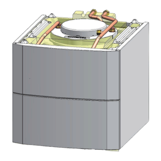
100 HL 5. Installation Positioning the appliance CAUTION Have 2 people available. Handle the appliance with gloves. 1. Remove the packaging from the DHW calorifier, leaving the calorifier on the pallet used for transport. 2. Remove the protective packaging. M002343-C 3. - Page 16 5. Installation 100 HL 4. Remove the front panel by pulling firmly from both sides. M002411-C 5. Lift the calorifier and position it in its operating location. M002345-D 6. Level the DHW tank using the adjustable feet. (1) Adjustment range: 0 to 20 mm M002346-F 22/08/2014 - 300026877-001-02...
-
Page 17: Fitting The Dhw Sensor
100 HL 5. Installation Fitting the DHW sensor 1. Remove the inspection trap insulation. 2. Put the DHW sensor in place. 3. Route the cable through the cable feed-through to the back of the DHW tank. M002356-D Installing the domestic hot water temperature sensor - Cable routing 1. -
Page 18: Hydraulic Connections
5. Installation 100 HL Boiler type Output (kW) Diaphragm Floor-standing condensing oil boiler 18 1. Unscrew the nut 1". 2. Remove the sheet gasket. Discard the sheet gasket. 3. Insert the gasket + diaphragm + gasket unit between the pipe and the heating pump. - Page 19 100 HL 5. Installation n Provision for Switzerland Make the connections according to the instructions of the Société Suisse de l’Industrie du Gaz et des Eaux. Comply with local instructions from water distribution plants. n Safety valve CAUTION In compliance with the safety rules, fit a safety valve to the domestic cold water tank inlet.
- Page 20 5. Installation 100 HL n Isolating valves Hydraulically isolate the primary and secondary circuits using stop valves to facilitate maintenance operations on the unit. The valves make it possible to carry out maintenance on the calorifer and its components without draining the entire installation. These valves are also used to isolate the calorifer unit when conducting a pressurised check on the leak tightness of the installation if the test pressure is greater than the admissible operating...
-
Page 21: Electrical Connections
100 HL 5. Installation n Pressure reducer If the mains pressure exceeds 80% of the calibration of the valve or safety unit (e.g. 5,5 bar (0,55 MPa) for a safety unit calibrated to 7 bar (0,7 MPa)), a pressure reducer must be installed upstream of the appliance. -
Page 22: Connecting The Dhw Heating Pump
5. Installation 100 HL 5.9.3. Connecting the DHW heating pump Connect the DHW heating pump to the corresponding terminal block on the boiler (Terminal X4). ¼See chapter: "Terminal block", page 22 L000232-D 5.9.4. Connecting the plate exchanger outlet Connect the domestic hot water temperature sensor cable to the corresponding terminal block on the boiler (Terminal X20). -
Page 23: Terminal Block
100 HL 5. Installation 5.9.6. Terminal block n Gas fired floor-standing condensing boiler (Only on boilers fitted with a SCU board) C003901-A X20: Connect the plate exchanger sensor. X4: Connect the DHW pump. S.ECS: Connect the DHW sensor. TA-: Connect the DHW tank anode. n Floor-standing condensing oil boiler (Only on boilers fitted with a SCU board) C003902-A... -
Page 24: 5.10 Filling The System
5. Installation 100 HL TA-: Connect the DHW tank anode. 5.10 Filling the system 5.10.1. Filling the domestic hot water circuit Bleeding tap Flexible discharge pipe 1. Rinse the domestic circuit. 2. Open a hot water tap. 3. Completely fill the domestic hot water calorifer via the cold water inlet pipe, leaving the hot water valve open. -
Page 25: Commissioning
100 HL 6. Commissioning Commissioning Check points before commissioning 6.1.1. Hydraulic circuits n Secondary circuit (domestic water) Inspect all the connections in the system for leaks. Setting the speed of the heating pump: Boiler type Output (kW) Set speed (3 positions) Floor-standing condensing gas boiler 10/15 C003497-C Boiler type... -
Page 26: Commissioning Procedure
6. Commissioning 100 HL Commissioning procedure CAUTION Initial commissioning must be done by a qualified professional. CAUTION During the heating process, a certain amount of water may flow through the valve or safety unit, this is caused by water expansion. This phenomenon is completely normal and must in no event be hindered. -
Page 27: Checking And Maintenance
100 HL 7. Checking and maintenance Checking and maintenance General instructions CAUTION Maintenance operations must be done by a qualified engineer. Only original spare parts must be used. Safety valve or safety unit The safety valve or unit on the domestic cold water inlet must be operated at least once a month to ensure proper operating and to prevent from any overpressure which may that may damage the domestic hot water calorifier. -
Page 28: Cleaning The Plate Heat Exchanger
7. Checking and maintenance 100 HL 4 The LED is on and steady. Change the board. Cleaning the plate heat exchanger We recommend cleaning the plate exchanger annually in order to maintain optimal performance. 1. Remove the front panel by pulling firmly from both sides. M002415-C 2. -
Page 29: Draining The Installation
100 HL 7. Checking and maintenance 3. Remove the inlet and outlet pipes from the plate exchanger (A=Boiler side). 4. Dismantle the plate heat exchanger. Clean the plate exchanger with a descaling product (e.g. citric acid with a pH of approximately 3). Rinse with clean water. - Page 30 7. Checking and maintenance 100 HL C003750-B 1. Unscrew the snap coupling. 2. Disconnect the two parts. 3. Proceed with the desired maintenance operation. 4. To re-assemble, proceed in reverse order. 22/08/2014 - 300026877-001-02...
-
Page 31: Maintenance Form
100 HL 7. Checking and maintenance Maintenance form Date Checks made Remarks Signature _____ _________ ______________________________ _____________________ _______________ ____________ 22/08/2014 - 300026877-001-02... -
Page 32: Spare Parts
8. Spare parts 100 HL Spare parts General When it is observed subsequent to inspection or maintenance work that a component in the appliance needs to be replaced, use only original spare parts or recommended spare parts and equipment. To order a spare part, give the reference number shown on the list. -
Page 33: Spare Parts
100 HL 8. Spare parts Spare parts 42 43 C003498-H Markers Reference Description 100016430 Foam coated domestic hot water tank 100HL 200019498 Enamelled stopper 200011817 Impressed current anode 89705511 Gasket 7 mm + Retainer ring 5 mm 95362447 KVT60 sensor - Length 2 m 300008957 2 PIN DHW probe connector 95362441 Temperature sensor... - Page 34 8. Spare parts 100 HL Markers Reference Description 300024887 Sensor cable 200011579 ACI anode cable - Length 2,5 m 300024943 Insulation, buffer tank 300024957 Sheet metal plate for fitting the exchanger / Regulation 300024956 Plate heat exchanger E6TH x 18 - G 3/4 300024451 Adjustable foot M8x45 200019651 DHW tank screw bag 200019652 DHW tank gasket bag...
-
Page 35: Warranty
100 HL 9. Warranty Warranty General You have just purchased one of our appliances and we thank you for the trust you have placed in our products. Please note that your appliance will provide good service for a longer period of time if it is regularly checked and maintained. Your installer and our customer support network are at your disposal at all times. - Page 36 9. Warranty 100 HL The warranty is limited to the exchange or repair of such parts as have been recognised to be faulty by our technical department and does not cover labour, travel and carriage costs. The warranty shall not apply to the replacement or repair of parts damaged by normal wear and tear, negligence, repairs by unqualified parties, faulty or insufficient monitoring and maintenance, faulty power supply or the use of unsuitable fuel.
- Page 37 100 HL 9. Warranty 22/08/2014 - 300026877-001-02...
- Page 40 © Copyright All technical and technological information contained in these technical instructions, as well as any drawings and technical descriptions supplied, remain our property and shall not be multiplied without our prior consent in writing. 22/08/2014 300026877-001-02...
Need help?
Do you have a question about the DHW 100 HL and is the answer not in the manual?
Questions and answers