DeDietrich KALIKO ESSENTIEL ETWH 180 E Installation And Service Manual
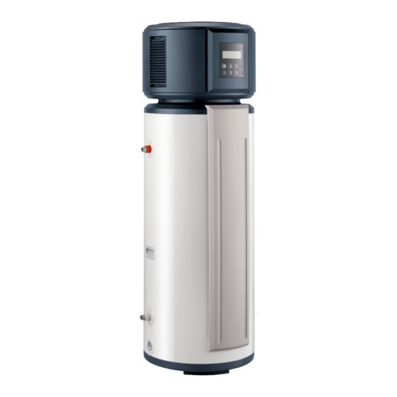
Thermodynamic water heater
Hide thumbs
Also See for KALIKO ESSENTIEL ETWH 180 E:
- User manual (36 pages) ,
- Installation and service manual (464 pages)

Related Manuals for DeDietrich KALIKO ESSENTIEL ETWH 180 E


Summary of Contents for DeDietrich KALIKO ESSENTIEL ETWH 180 E
- Page 1 Ireland EASYLIFE KALIKO ESSENTIEL Installation and Service Manual Thermodynamic water heater KALIKO ESSENTIEL ETWH 180 E ETWH 230 E S U S T A I N A B L E C O M F O R T ®...
-
Page 2: Table Of Contents
Contents Contents Safety ................... . 5 General safety instructions . - Page 3 Contents 6.2.1 Installation of the thermodynamic water heater ..........29 Hydraulic connections .
- Page 4 Contents 14.2.2 General checks ............... 56 14.2.3 Electrical checks .
-
Page 5: Safety
1 Safety Safety General safety instructions Danger This appliance can be used by children aged from 8 years and above and persons with reduced physical, sensory or mental capabilities or lack of experience and knowledge if they have been given supervision or instruction concerning use of the appliance in a safe way and understand the hazards involved. - Page 6 1 Safety Important Never remove or cover the labels and data plates affixed to appliances. Labels and data plates must be legible throughout the entire lifetime of the appliance. Immediately replace damaged or illegible instructions and warning stickers. Caution If the home is unoccupied for a long period and there is a risk of frost, drain the water heater.
-
Page 7: Instructions On The Hydraulic Connections
1 Safety Instructions on the hydraulic connections Warning Do not touch the refrigeration connection pipes with your bare hands while the thermodynamic water heater is running. Danger of burn or frost injury. Warning Refrigerant fluid and pipes: Use only R-134a refrigerant fluid to fill the system. - Page 8 1 Safety Danger In the event of a refrigerant leakage: 1. Do not use a naked flame, do not smoke, do not operate electrical contacts or switches (doorbell, light, motor, lift, etc.). 2. Open the windows. 3. Switch off the appliance. 4.
-
Page 9: Specific Safety Instructions
1 Safety Specific safety instructions Warning In accordance with the NFC 15.100 electrical safety standard, only qualified professionals are permitted access to the inside of the appliance. Warning Ensure correct earthing. Heating water and domestic water must not come into contact with each other. A disconnection device must be fitted to permanent pipes in accordance with installation rules. -
Page 10: Liabilities
1 Safety Liabilities 1.4.1 Manufacturer's liability Our products are manufactured in compliance with the requirements of the various Directives applicable. They are therefore delivered with the marking and any documents necessary. In the interests of the quality of our products, we strive constantly to improve them. We therefore reserve the right to modify the specifications given in this document. -
Page 11: Composition Of/Information On The Ingredients
1 Safety Product classification: This product is not classified as a "hazardous preparation" according to European Union regulations. 1.5.3 Composition of/Information on the ingredients Chemical nature: 1,1,1,2 - Tetrafluoroethane R-134a. Ingredients that may lead to hazardous situations: Tab.1 Fluid ingredients R-134a Substance name Concentra... -
Page 12: In The Event Of Accidental Spillage
1 Safety Effect of heat: release of toxic and corrosive vapours. Special intervention methods: Cool the volumes exposed to heat with water spray. Protection of the firemen: Full self-contained breathing apparatus. Complete body protection. 1.5.6 In the event of accidental spillage Individual precautions: Avoid contact with the skin and eyes. -
Page 13: Regulations
1 Safety Do not drink, eat or smoke in the work place. 1.5.9 Regulations Regulation (UE) 517/2014 relating to fluorinated greenhouse gases. Classified installations No. 1185 Website The installation manual can also be found on our website. 7629886 - v07 - 20072020 ETWH... -
Page 14: About This Manual
2 About this manual About this manual General This manual is intended for installers of ETWH 180 E or ETWH 230 E thermodynamic water heaters. Available documentation Installation and service manual. User manual. Symbols used 2.3.1 Symbols used in the manual This manual uses various danger levels to draw attention to special instructions. -
Page 15: Technical Specifications
3 Technical specifications Technical specifications Homologations 3.1.1 Certifications NF certification Appliances concerned: ETWH 180 E, ETWH 230 E. Specifications LCIE 103–15/B (July 2011) for NF Electricity Performance Marking This product complies with the requirements of the following NF Electricity Standards: EN 60335-1:2012 + A11:2014 EN 60335-2-21:2003 + A1:2005 + A2:2008 EN 60335-2-40:2003 + A11:2004 + A12:2005 + A1:2006 + A2:2009 +... - Page 16 3 Technical specifications Model Unit ETWH 180 E ETWH 230 E Sound power level, indoors (L Storage volume (V) Litre 180.0 230.0 Mixed water at 40°C (V40) Litre Heat input (HP) 1000 / 1500 1000 / 1500 Absorbed electrical power (HP) / 460 / 460 COP in accordance with the EN16147 standard...
-
Page 17: Dimensions And Connections
3 Technical specifications Important The values in tonnes of CO equivalent are calculated using the following formula: quantity (in kg) of refrigerant fluid x GWP / 1000. GWP = Global Warming Potential. The GWP of R-134a is 1430. Important R-134a refrigerant is contained in equipment that has been hermetically sealed. -
Page 18: Electrical Diagram
3 Technical specifications Electrical diagram 3.4.1 Water heater ETWH 180 E and ETWH 230 E Fig.3 Electrical diagram C AP 1 CN27 CN1 4 Gray White Yellow/Green C N 8 M ain Control Board CN2 5 C T 2 CN1 8 CT 1 CN2 1 RY1 3... - Page 19 3 Technical specifications Connector Description Neutral Live Earth Off Peak Peak rate/Off-peak rate Inductor Inductor Electric Heater Electrical back-up Electrical back-up relay Compressor relay RY12 / RY13 / RY14 Relay connection ATCO Safety thermostat on the electrical back-up Immersion heater control system sensor XP1 / XP2 Connectors XS1 / XS2...
-
Page 20: Description Of The Product
4 Description of the product Description of the product General description ETWH thermodynamic water heaters have the following specifications: Floor-standing thermodynamic water heater with heat pump taking energy from the ambient air. Control panel with display of the hot water temperature in the domestic hot water tank and timer programming. - Page 21 4 Description of the product If the room temperature is outside the heat pump's operating range, it will cease the function. The water heater automatically activates the immersion heater and the LA icon on the control panel will come on. The room temperature range adapted for this operating mode is between +3°C and +43°C.
-
Page 22: Operating Principle For The Anti-Legionella Function
4 Description of the product The thermodynamic water heater can heat the water using the following sources of energy: heat pump or immersion heater: the heat pump operates as the priority source, the immersion heater starts when the heat pump is operating, to enable the required temperature set point to be reached before the end of the period. -
Page 23: Main Components Of The Thermodynamic Water Heater
4 Description of the product Main components of the thermodynamic water heater Fig.6 1 Top cover 2 Back cover 3 Front cover 4 Axial fan 5 Evaporator assembly 6 Magnesium anode 7 Domestic hot water outlet 8 Power supply cable 9 Condenser 10 Domestic cold water inlet 11 Finishing clamp for the drainage plug... -
Page 24: Control Panel Description
4 Description of the product Control panel description 4.4.1 Description of the control keys Fig.7 1 ON/OFF key 2 ON indicator (green) 3 Access to the clock for setting Cancellation key ECONOMY MODE Screen unlocking key 5 Access to adjust the start-up time on the programmer TEMP HYBRID MODE 6 Access to adjust the shut-down time on the programmer... -
Page 25: Before Installation
5 Before installation Before installation Regulations governing installation Caution The appliance must be installed and maintained by a certified professional in accordance with prevailing statutory texts and codes of practice. Important Pursuant to Article L. 113-3 of the French Consumer Code, this equipment must be installed by a certified operator whenever a refrigerant connection is necessary (the case with split systems, even when fitted with a quick coupling device). -
Page 26: Location Of The Water Heater
5 Before installation 5.2.2 Location of the water heater Caution When installing the appliance, abide by the IP21 protection rating. Caution Do not install the thermodynamic water heater in premises exposed to gas, vapours or dust. Install the thermodynamic water heater in a dry, frost-free room at a minimum temperature of 5°C. -
Page 27: Transport
5 Before installation Ventilation Fig.11 Clearance to be provided for the Respect the minimum dimensions shown on the diagram. thermodynamic water heater Respect the distances on either side of the water heater and between the back of the appliance and the internal wall of the premises. V >15m ETWH 180 E ETWH 230 E... -
Page 28: Unpacking & Initial Preparation
5 Before installation Caution Have 2 people available. Use a 3-wheel hand trolley, positioning the appliance against the rear surface of the item. Handle the appliance with gloves. Fig.13 Important We recommend shipping the appliance vertically. However, it can be tilted during shipping and unpacking. MW-1000693-1 Unpacking &... -
Page 29: Installation
6 Installation Installation General Important Pursuant to Article L. 113-3 of the French Consumer Code, this equipment must be installed by a certified operator whenever a refrigerant connection is necessary (the case with split systems, even when fitted with a quick coupling device). Preparation 6.2.1 Installation of the thermodynamic water heater... -
Page 30: Connecting The Domestic Water Circuit
6 Installation 6.3.1 Connecting the domestic water circuit Caution When making the connection, it is imperative that the standards and corresponding local directives be respected. Specific precautions Before making the connection, flush the domestic water inlet pipes in order not to allow metal or other particles into the appliance's tank. Fig.15 Water circuit connections 1. -
Page 31: Hydraulic Connection Between The Thermodynamic Water Heater And An Instant Boiler
6 Installation 6.3.2 Hydraulic connection between the thermodynamic water heater and an instant boiler Example of hydraulic connection in HYBRID Mode Fig.16 °C 230V 50Hz MW-5000495-1 1 Thermodynamic water heater 2 Instant boiler 6.3.3 Connecting the condensate discharge pipe 1. Insert the condensate collector hose (Ø 9 mm) into the discharge opening. - Page 32 6 Installation Install the safety valve close to the water heater in a place with easy access. Sizing The diameter of the safety unit and its connection to the water heater must be at least equal to the diameter of the domestic cold water inlet on the water heater.
-
Page 33: Electrical Connections
6 Installation Electrical connections 6.4.1 Recommendations Caution Only qualified professionals may carry out electrical connections, always with the power off. Caution Do not connect the power supply directly to the Peak rate/Off- peak rate contact. The connection is made on the terminal block. Caution To ensure the conformity of electrical installation, the appliance must be powered by a circuit comprising an omnipolar switch with... -
Page 34: Connecting The Appliance
6 Installation 6.4.2 Connecting the appliance Caution Ensure the polarities shown on the terminals are followed: live (L), neutral (N) and earth ( Fig.17 Connection 1. Connect the connection cable already wired into the distribution board. 6.4.3 Types of connections to the distribution board There are different types of electrical connection for the thermodynamic water heater depending on the end user's requirements. - Page 35 6 Installation Fig.18 538 kW/h 15 / 45 A 500 mA C1 C2 40 A 16 A TEST MW-1000695-1 1 Thermodynamic water heater 4 AC-type differential switch 2 Meter 5 Circuit breakers 3 Connection circuit breaker 7629886 - v07 - 20072020 ETWH...
- Page 36 6 Installation Fig.19 Example of electrical connection in OPT.BACKUP mode or with PEAK RATE/OFF-PEAK RATE cables – Assembly 1 538 kW/h 15 / 45 A 500 mA C1 C2 40 A 16 A TEST Auto MW-5000494-1 1 Thermodynamic water heater 4 AC-type differential switch 2 Meter 5 Circuit breakers...
-
Page 37: Filling The System
6 Installation Fig.20 Example of electrical connection in OPT.BACKUP mode or with PEAK RATE/OFF-PEAK RATE cables – Assembly 2 538 kW/h 15 / 45 A 500 mA C1 C2 16 A TEST MW-5000493-1 1 Thermodynamic water heater 4 AC-type differential switch 2 Meter 5 Circuit breakers 3 Connection circuit breaker... - Page 38 6 Installation Fig.21 Filling the tank 1. Open a hot water tap. 2. Open the cold water tap to vent any air in the installation, ensuring that valve A on the drain opening is properly closed. 3. The water heater starts to fill up and any air exits via the hot water taps.
-
Page 39: Commissioning
7 Commissioning Commissioning General Commissioning of the thermodynamic water heater should be carried out: When it is used for the first time; After a prolonged shut-down; After any event that may require complete reinstallation. Important Commissioning of the thermodynamic water heater allows the user to review the various settings and checks to be made to start up the water heater in complete safety. -
Page 40: Checks After Commissioning
7 Commissioning Checks after commissioning 7.4.1 Points to check after commissioning Fig.22 Checks 1. Check the tightness of the connections. 2. Check the water pressure. 3. Check that there are no errors on the regulator. 4. Check the temperature on the domestic hot water temperature sensor to ensure that the appliance is working correctly. -
Page 41: Operation
8 Operation Operation Use of the control panel Automatic key lockout: If the control panel keys are not used for a period of 1 minute, the keys are locked. Pressing and holding the CANCEL key enables the control panel to be unlocked Automatic screen lock: If there is no action on the control panel, the screen backlighting goes... -
Page 42: Settings
9 Settings Settings List of parameters The following parameters can be accessed in all operating modes: ECONOMY MODE / HYBRID MODE / OPT.BACKUP Tab.7 Parameters available in the operating modes Parameter Description Factory setting Water temperature difference between the set point and the 5°C restart. -
Page 43: Reading Out Measured Values
9 Settings Fig.27 The anti-legionella function is configured directly on the PCB using the switch SW1–3. MW-4000184-1 Fig.28 Anti-legionella mode 1. Remove the top cover. 2. Remove the front panel. 3. Open the cover on the electronic control box to access the PCB. Default setting for the anti-legionella function: SW1–3 : OFF 65°C SW1–4 : OFF anti-legionella mode disabled... -
Page 44: List Of Operating Parameters
9 Settings Fig.30 3. Press the arrows to show the measured values one by one (refer to the table below). 4. Exit the measured values menu by waiting for 10 seconds. 9.3.2 List of operating parameters Parameter Description Unit Water temperature in the domestic hot water tank °C Measured room temperature °C... -
Page 45: 10 Maintenance
10 Maintenance 10 Maintenance 10.1 General Caution The appliance must be installed and maintained by a certified professional in accordance with prevailing statutory texts and codes of practice. Caution Before working on the appliance, ensure that it is switched off and safe. -
Page 46: Magnesium Anode
10 Maintenance Caution Risk of injury on the sharp-edged fins. Caution Do not distort or damage the fins. Clean the evaporator at regular intervals using a soft-haired brush. Carefully realign the fins using a suitable comb if they are bent. Cleaning the fan: Check the cleanliness of the fan once a year. -
Page 47: Maintenance Form
10 Maintenance Caution Failure to comply with this maintenance rule may cause damage to the water heater tank and invalidate its warranty. 10.3 Maintenance form Tab.8 Date Checks made Remarks Signature 7629886 - v07 - 20072020 ETWH... -
Page 48: 11 Troubleshooting
11 Troubleshooting 11 Troubleshooting 11.1 Messages (Ex and Px type codes) If a malfunction occurs, the screen displays an error code beside the water temperature indicator: the “ALARM” pictogram appears, the audible signal sounds. 1. Make a note of the code displayed. The code is important for the correct and rapid diagnosis of the type of error and for any technical assistance that may be needed. -
Page 49: Deleting The Error Codes
11 Troubleshooting For more information, see Operating principle with the different MODES, page 20 11.2 Deleting the error codes 1. Delete the error codes from the control panel memory by simultaneously pressing the TIME ON and CANCEL keys. TIME CANCEL After these 2 buttons are pressed simultaneously, an audible signal Press 3s for unlock... -
Page 50: 12 Disposal/Recycling
12 Disposal/recycling 12 Disposal/recycling 12.1 General 12.1.1 Considerations relating to disposal Product waste: consult the manufacturer or the supplier for information on recovery or recycling. Soiled packaging: reuse or recycle after decontamination. Destroy in authorised installations. Caution This appliance bears the recycling symbol pursuant to European Directive 2012/19/EC on Waste from Electrical and Electronic Equipment (WEEE). -
Page 51: 13 Spare Parts
13 Spare parts 13 Spare parts 13.1 General When it is observed subsequent to inspection or maintenance work that a component in the appliance needs to be replaced, use only original spare parts or recommended spare parts and equipment. To order a spare part, give the reference number shown on the list. 7629886 - v07 - 20072020 ETWH... -
Page 52: Spare Parts Lists
13 Spare parts 13.2 Spare parts lists 13.2.1 Heat pump Fig.33 12.1 12.2 11.1 11.2 10.3 10.2 21.7 10.1 21.3 21.2 21.1 21.6 21.4 21.5 ETWH 7629886 - v07 - 20072020... - Page 53 13 Spare parts Tab.10 List of spare parts for ETWH 180 E and ETWH 230 E Markers References Components 7628460 Top cover 7628461 Axial fan 7628508 Fan motor 7628473 Fan bracket 7628475 Air duct 7628469 Air filter 7628487 Evaporator assembly 7628499 Evaporator inlet pipe 7628495...
-
Page 54: Thermodynamic Water Heater
13 Spare parts 13.2.2 Thermodynamic water heater Fig.34 ETWH 7629886 - v07 - 20072020... - Page 55 13 Spare parts Markers References Components 7628471 Front panel 7628515 Magnesium anode 7628482 Cover for magnesium anode and/or electric resistor 7628504 T5 sensor 7628481 T5 sensor bracket 7628506 Control system thermostat 7628478 Safety thermostat bracket 7628507 Safety thermostat 7628518 Electrical back-up power supply cover 7628512 Electrical back-up 7628514...
-
Page 56: 14 Appendix
14 Appendix 14 Appendix 14.1 EC Declaration of Conformity The unit complies with the standard type described in the EC declaration of conformity. It has been manufactured and put into circulation in accordance with the requirements of the European Directives. The original declaration of conformity is available from the manufacturer. - Page 57 14 Appendix 14.3 Maintenance protocol For more information, see Standard inspection and maintenance operations, page 45 7629886 - v07 - 20072020 ETWH...
- Page 58 14 Appendix ETWH 7629886 - v07 - 20072020...
- Page 59 © Copyright All technical and technological information contained in these technical instructions, as well as any drawings and technical descriptions supplied, remain our property and shall not be multiplied without our prior consent in writing. Subject to alterations.
- Page 60 DE DIETRICH FRANCE Direction de la Marque 57, rue de la Gare - F-67580 Mertzwiller 03 88 80 27 00 03 88 80 27 99 www.dedietrich-thermique.fr VAN MARCKE NV 000 «БДP T » LAR Blok Z, 5 129164, Россия, г. Москва...
Need help?
Do you have a question about the KALIKO ESSENTIEL ETWH 180 E and is the answer not in the manual?
Questions and answers