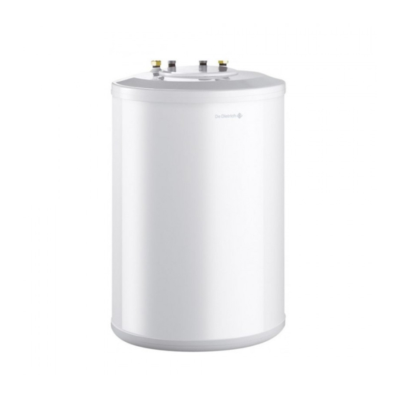
Summary of Contents for DeDietrich SR 130
- Page 1 SR 130 English Domestic hot water tanks 29/05/06 Installation instructions Instructions for use Technical instructions...
-
Page 2: Table Of Contents
Spare parts - SR 130 ........ -
Page 3: Introduction
Introduction SR 130 domestic hot water calorifiers are connected to gas-fired For a proper operating of the boiler, follow carefully the wall-hung boilers from the City 1.24 - 1.24FF - 3.24 and 3.24FF range instructions. and to gas-fired wall-hung condensation boilers from the DPSM3 15 LP - DPSM3 25 LP - MC 15 LP and MC 25 LP - MCR 24 range. -
Page 4: Main Dimensions
Primary outlet G 3/4 Domestic hot water outlet R 3/4 - Red marking Domestic cold water temperature R 3/4 - Blue marking Magnesium anode Sensor tube R: Conical thread G: Exterior cylinder thread, sealed by flat joint SR 130 29/05/06 - 300009755-001-H... -
Page 5: Technical Characteristics
- Boiler CITY EE 26 - DPSM or MC boiler HC 13 - Boiler MCR 24 HG 30 Sensor: - Boiler CITY AD 138 - DPSM or MC boiler AD 212 - Boiler MCR 24 AD 226 29/05/06 - 300009755-001-H SR 130... -
Page 6: Installation
Installation Installation must be carried out in accordance with the SR 130 calorifiers are designed to be placed under the wall-hung prevailing regulations, the codes of practice and the boiler. recommendations in these instructions. 1 Connecting the DHW tank to the boiler (primary circuit) - Page 7 Connecting the calorifier to a DPSM3 or MC boiler Primary input Domestic hot water outlet Domestic cold water inlet Primary outlet 29/05/06 - 300009755-001-H SR 130...
- Page 8 Connecting the calorifier to a MCR 24 boiler Primary input Domestic hot water outlet Domestic cold water inlet Primary outlet SR 130 29/05/06 - 300009755-001-H...
-
Page 9: Connecting The Tank To The Domestic Water Circuit (Secondary Circuit)
The outlet pipe in the valve or safety unit must not be blocked. France The level of the safety unit must be lower than that of the cold water inlet to enable draining. Otherwise, fit a drainage pipe to the lowest point of the tank. 29/05/06 - 300009755-001-H SR 130... - Page 10 Cold water inlet with an integrated non-return valve b. Connection to the DHW tank cold water inlet c. Stop cock d. safety unit 7 bar e. Drain opening Germany: 10-bar safety valve Domestic hot water outlet SR 130 29/05/06 - 300009755-001-H...
-
Page 11: Assembly And Connection Of The Domestic Hot Water Sensor
Connecting the DHW sensor to a CITY boiler The connection for the domestic hot water sensor can be found on the back of the boiler control panel under the little flap. Cut the power supply to the boiler. 29/05/06 - 300009755-001-H SR 130... - Page 12 Connecting the DHW sensor to a DPSM3 or MC boiler Cut the power supply to the boiler. SR 130 29/05/06 - 300009755-001-H...
-
Page 13: Commissionning
During the heating process, a certain amount of water may flow through the valve or safety unit; this is caused by water expansion. This phenomenon is completely normal and must in no event be hindered. 29/05/06 - 300009755-001-H SR 130... -
Page 14: Maintenance And Periodic Checks
The screws retaining the visit trap must be tightened to 6 Nm +1/-0. Use a dynamometric spanner. Approximately 6 Nm is obtained by holding the box spanner by the small lever. 13. Switch on. 14. Re-assemble the cover A. SR 130 29/05/06 - 300009755-001-H... - Page 15 Maintenance form Date Checks made Comments Signature 29/05/06 - 300009755-001-H SR 130...
-
Page 16: Spare Parts - Sr 130
Spare parts - SR 130 29/05/06 - 8953-4129B to order a spare part, it is imperative to give the code number shown on the list, against the number of the part required. Reference Description 8953-8579 Complete Anode 8375-4945 Earth wire... - Page 17 Sub-assemblies such as motors, pumps, electric valves etc. are guaranteed only if they have never been dismantled. 29/05/06 - 300009755-001-H SR 130...
-
Page 18: Warranty Certificate
Date of purchase: ................Retailer's stamp: Name and address of the purchaser: ....................................................................................................................Tel.:....................Information on the appliance (to be found on the rating plate): Model: ....................Serial number: .................. SR 130 29/05/06 - 300009755-001-H... - Page 19 29/05/06 - 300009755-001-H SR 130...
- Page 20 DE DIETRICH THERMIQUE S.A.S. DE DIETRICH HEIZTECHNIK www.dedietrich.com www.dedietrich.com Direction des Ventes France Am Concorde Park 1 - B 4 / 28 57, rue de la Gare A-2320 SCHWECHAT / WIEN F- 67580 MERTZWILLER +43 (0)1 / 706 40 60-0...


Need help?
Do you have a question about the SR 130 and is the answer not in the manual?
Questions and answers