
Related Manuals for Lifetime 90056


Summary of Contents for Lifetime 90056
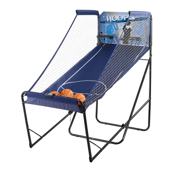
- Page 1 MODEL N° 90056 OWNER’S MANUAL Keep this Product ID Number and use when contacting Customer Service:...
- Page 2 Maintaining your privacy is our long-standing policy at Lifetime. And you can rest as- sured that Lifetime will not sell or provide your personal data to other third parties, or allow them to use your personal data for their own purposes.
- Page 3 SAFETY INSTRUCTIONS To ensure safety, do not attempt to assemble this product without reading and following all instructions carefully. Check the entire box and inside all packing materials for parts and/or additional instruction material. Before beginning assembly, identify and inventory all parts and hardware using the parts and hardware lists and identifi...
- Page 4 TOOLS AND PARTS REQUIRED FOR THIS ASSEMBLY (1, included) (1, included) *Two adults required to complete assembly*...
- Page 5 ASSEMBLY GUIDES Refer to the following areas throughout the instructions to assist in the assembly process: This area is located at the top, TOOLS AND HARDWARE REQUIRED FOR THIS PAGE left-hand corner of the page and indicates which tools and hardware are needed to on a page.
-
Page 6: Table Of Contents
PARTS LIST Item Description Backboard Ball Electronic Scoreboard Electronic Power Source Ball Return Net (not shown) Bottom Brace Cross Bar Rear Cross Brace Side Rail Side Rail with Push Button Height Spacer Ball Pump and Needle (not shown) Fold Up Warning Sticker (applied to BMD) HARDWARE LIST Item Description Hardware Blister Pack (1055075) -
Page 7: Backboard
PARTS IDENTIFIER Parts shown at 5% of Actual Size BLX (x2) BMC (x2) (x1) Backboard BLU (x1) BLY (x2) Bottom Brace BMD (x1) Side Rail with Push Button (Warning Sticker Applied) (x1) Side Rail (x1) BMB (x2) BMA (x2) BLZ (x2) Rear Cross Brace BLV (x2) (x2) -
Page 8: Rim
PARTS IDENTIFIER Parts shown at 10% of Actual Size BLP (x7) Ball AKZ (x2) BME (x2) ALX (x2) Height Spacer HARDWARE IDENTIFIER Hardware shown at Actual Size (x8) (x8) (x8) 3/8” x 1” Button Head Cap Screw 3/8” Cap Nut 3/8”... - Page 9 HARDWARE IDENTIFIER Hardware shown at Actual Size BMM (x5) 3/8” x 3 1/4” Button Head Cap Screw BMN (x2) Retaining Hook BOC (x1) 3/8” x 3 1/2” Button Head Cap Screw Hardware shown at Actual Size (x7) (x2) BML (x3) 3/8”...
-
Page 10: Electronic Scoreboard
BACKBOARD TO RIM ASSEMBLY HARDWARE REQUIRED Hardware shown at Actual Size (x8) (x8) (x8) 3/8” x 1” Button Head Cap Screw 3/8” Cap Nut 3/8” Washer AAP (x8) BNZ (x4) BOA (x4) #6 x 3/8” Phillips 15mm M5 Screw M5 Nylock Nut Pan Head Screw PARTS REQUIRED Parts shown at 10% of Actual Size... - Page 11 TOOLS AND HARDWARE REQUIRED FOR THIS PAGE BNZ (x4) BOA (x4) AAP (x8) Remove and discard the plastic shield from the Electronic Scoreboard (BLQ). Attach the Electronic Scoreboard to the with the hardware shown. Bottom wires to the outside Note: Make sure to orient the digital display right side up, and attach the sensors with white wires to the top positions.
- Page 12 TOOLS AND HARDWARE REQUIRED FOR THIS PAGE 9/16” (x8) (x8) (x8) Attach a Rim (ALX) to the with the hardware shown. WARNING Do not overtighten the Cap Nut. If the end of the Bolt breaks through the plastic cap, call our Customer Service Department.
- Page 13 TOOLS AND HARDWARE REQUIRED FOR THIS PAGE Attach the Nets (AKZ) to the Rims (ALX) as shown. Then set the Backboard and Rim Assembly aside until later in the assembly process.
- Page 14 HARDWARE REQUIRED Hardware shown at Actual Size (x11) BML (x3) 3/8” Cap Nut (x2) 3/8” x 2” Button Head Cap Screw 3/8” Washer BOB (x4) BMK (x2) 3/8” Plug 3/8” x 2 1/2” Button Head Cap Screw BMM (x5) BMN (x2) 3/8”...
-
Page 15: Bottom Brace
PARTS REQUIRED Parts shown at 5% of Actual Size BMC (x2) BLU (x1) Bottom Brace BMB (x2) BLZ (x2) Rear Cross Brace BMA (x2) BLY (x2) (x2) TOOLS REQUIRED... - Page 16 TOOLS AND HARDWARE REQUIRED FOR THIS PAGE If the system will be placed under a ceiling that is at least 7 feet 6 inches tall, press down on the push button on the Rear, Middle Leg (BMB) Height Spacer (BME) as shown. If the system will be placed under a ceiling that is 7 feet tall, do not perform this step.
- Page 17 TOOLS AND HARDWARE REQUIRED FOR THIS PAGE Press down on the push button on the Height Spacer (BME) (or the Rear, Middle Leg (BMB) if step 2.2 was not performed) and insert the swaged Rear, Top Leg (BMC) until the push button snaps into the hole indicated.
- Page 18 TOOLS AND HARDWARE REQUIRED FOR THIS PAGE 9/16” BMM (x2) (x2) Attach the Bottom Brace (BLU) to the Rear Bottom Legs (BMA) with the hardware shown. Make sure the hole in the center of the Bottom Brace is Only fingertighten the 3/8” Cap Nuts perpindicular to the ground as pictured.
- Page 19 TOOLS AND HARDWARE REQUIRED FOR THIS PAGE Attach the Rear Bottom Legs (BMA) Rear, Middle Leg (BMB) until the push button snaps into the hole indicated. Make sure next step. Snap push button into hole Press down on push button Side View Note: When assembled correctly, the lowest push button on the Left Leg will face a different direction than the lowest push button on the Right Leg.
- Page 20 TOOLS AND HARDWARE REQUIRED FOR THIS PAGE 9/16” BML (x3) (x3) Attach the Rear Cross Braces (BLZ) Bottom Brace (BLU) with the hardware shown. Only fingertighten the hardware until instructed to tighten all hardware later in the assembly. Do not overtighten the Cap Nut. Press down on the push button on the and insert Middle Leg (BLY) until...
- Page 21 TOOLS AND HARDWARE REQUIRED FOR THIS PAGE 9/16” BOC (x1) (x2) BMM (x1) to the Rear Bottom Brace (BLU) with the hardware shown. Only fingertighten the hardware until instructed to tighten it later in the assembly. Do not overtighten the Cap Nut.
- Page 22 TOOLS AND HARDWARE REQUIRED FOR THIS PAGE 9/16” BMM (x2) (x2) the Bottom Brace (BLU) with the hardware shown. Do not overtighten the Cap Nut. Note: Tighten all hardware now.
-
Page 23: Bmn
TOOLS AND HARDWARE REQUIRED FOR THIS PAGE (x2) 9/16” BMK (x2) BMN (x2) (x2) (Not to scale) Attach the Backboard Assembly to the Rear, Top Legs (BMC) with the hardware shown. Do not overtighten the Cap Nut. - Page 24 TOOLS AND HARDWARE REQUIRED FOR THIS PAGE BOB (x4) With the help of another adult, rotate the Rear Frame Assembly 2.10 upright as shown. Insert 3/8” Plugs (BOB) into the holes indicated. 2.11...
-
Page 25: 3/8" X 2 1/2" Button Head Cap Screw
HARDWARE REQUIRED Hardware shown at Actual Size BML (x3) (x7) (x2) 3/8” x 2” Button Head Cap Screw 3/8” Cap Nut 3/8” Washer BMK (x2) BPI (x1) 3/8” x 2 1/2” Button Head Cap Screw 1 1/2” x 1/2” Spacer BMM (x1) 3/8”... - Page 26 TOOLS AND HARDWARE REQUIRED FOR THIS PAGE Press down on the push button on the Side Rail with Push Button (BMD) and insert the swaged end of the Side Rail into the until the push button snaps into the hole indicated. Press down on push button Snap push button...
- Page 27 TOOLS AND HARDWARE REQUIRED FOR THIS PAGE Lean Bar until the push buttons snap into the holes indicated. Clip the Straps together through the loops on both sides of the Ball Return Net near the sleeve. Strap Snap push button into hole Double-headed Press down on...
-
Page 28: Bmm
TOOLS AND HARDWARE REQUIRED FOR THIS PAGE 9/16” BOC (x1) BMM (x1) (x2) Attach the Front Frame Assembly to the Rear Frame Assembly with the hardware shown. Press down on the double headed push button on the into the holes indicated on the Snap double-headed push button into holes Do not overtighten the Cap Nut. -
Page 29: Bpi
TOOLS AND HARDWARE REQUIRED FOR THIS PAGE 9/16” BML (x1) (x1) BPI (x1) Slide the 3/8” x 2” Button Head Cap Screw (BML) through the 1 1/2” x 1/2” Spacer (BPI) . Attach with the hardware shown. Do not overtighten the Cap Nut. - Page 30 TOOLS AND HARDWARE REQUIRED FOR THIS PAGE 9/16” BMK (x2) (x2) (x2) Slide the Ball Return Net (BLS) over the Rear, Top Legs (BMC). Hook the Upper Straps of the Ball Return Net under the Retaining Hooks (BMN) as shown. Strap Strap Slide a Cross Bar (BLV) into the sleeve of the Ball Return Net (BLS).
- Page 31 TOOLS AND HARDWARE REQUIRED FOR THIS PAGE 9/16” BML (x2) (x2) Position the other Cross Bar (BLV) on the inside of the Ball Return Net (BLS) as shown. Then attach the Cross Bar to the Front Frame Assembly with the hardware shown.
- Page 32 TOOLS AND HARDWARE REQUIRED FOR THIS PAGE Connect the Electronic Power Source (BLR) to the Electronic Scoreboard (BLQ) as shown. How to Play: Each game consists of a possible 3 rounds. In the first round, each player has 30 seconds to reach 30 points and move on to round 2. Each basket is worth 2 points for the first 20 seconds, and 3 points for the last 10 seconds.
- Page 33 ® ENHANCE YOUR LIFETIME PURCHASE BY ADDING ACCESSORIES OR OTHER GREAT PRODUCTS: To purchase accessories or other Lifetime Products, visit us at: www.lifetime.com Or call: 1-800-424-3865...
- Page 34 If the Warning Label is illegible, destroyed or removed, contact Customer Service for a replacement. WARNING Do not climb on the structure of the Double Shot system. 1052685 The Warning Label is located on the Ball Return Net at the front of the system. The Pinch Warning stickers are located on the Fold-up Plates on the left side of the system near the bottom.
- Page 35 NOTES...
- Page 36 WARRANTY INFORMATION UNAVAILABLE OR OBSOLETE. material or workmanship for a period of ninety days from the date of original retail purchase. The word “defects” is defi ned as imperfections that impair the use of the product. Defects resulting from misuse, abuse or negligence will void this warranty.
Need help?
Do you have a question about the 90056 and is the answer not in the manual?
Questions and answers