
Related Manuals for Lifetime 90056


Summary of Contents for Lifetime 90056
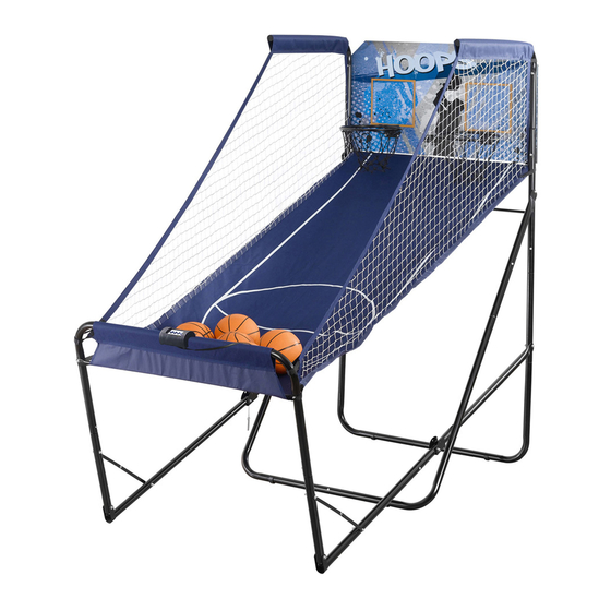
- Page 1 MODEL N° 90056 OWNER’S MANUAL Keep this Product ID Number and use when contacting Customer Service:...
- Page 2 REGISTER YOUR PRODUCT ONLINE AT WWW.LIFETIME.COM At Lifetime, we are committed to providing innovative and quality products. While registering, you will have the opportunity to give us your feedback. Your input is valuable to us. Lifetime’s Promise to You: REGISTER today! Save this owner’s manual for future reference and in the event that...
- Page 3 SAFETY INSTRUCTIONS FAILURE TO FOLLOW THESE WARNINGS MAY RESULT IN SERIOUS INJURY OR PROPERTY DAMAGE AND WILL VOID WARRANTY. Most injuries are caused by misuse and/or not following instructions. Use caution when using this product. BEFORE BEGINNING ASSEMBLY...
- Page 4 TOOLS AND PARTS REQUIRED FOR THIS ASSEMBLY 9/16” Wrench Allen Key This system is intended for indoor use only. *Two adults required to complete assembly* Only adults should set up the product. Do not allow children in the setup area until assembly is complete.
- Page 5 ASSEMBLY GUIDES Refer to the following areas throughout the instructions to assist in the assembly process: This area is located at the top, TOOLS AND HARDWARE REQUIRED FOR THIS PAGE left-hand corner of the page and indicates which tools and hardware are needed to complete the assembly steps on a page.
-
Page 6: Parts List
PARTS LIST Item Description HARDWARE LIST Item Description Hardware Blister Pack (1055075) -
Page 7: Parts Identifier
PARTS IDENTIFIER Parts shown at 5% of Actual Size Parts shown at 10% of Actual Size... -
Page 8: Hardware Identifier
PARTS IDENTIFIER Parts shown at 10% of Actual Size HARDWARE IDENTIFIER BACKBOARD TO RIM ASSEMBLY HARDWARE Hardware shown at Actual Size REAR FRAME ASSEMBLY HARDWARE Hardware shown at Actual Size... - Page 9 HARDWARE IDENTIFIER REAR FRAME ASSEMBLY HARDWARE (CONTINUED) Hardware shown at Actual Size FRONT FRAME ASSEMBLY HARDWARE Hardware shown at Actual Size...
-
Page 10: Hardware Required
BACKBOARD TO RIM ASSEMBLY HARDWARE REQUIRED Hardware shown at Actual Size PARTS REQUIRED Parts shown at 10% of Actual Size Part shown at 5% of Actual Size TOOLS REQUIRED Allen Key 9/16" Wrench... - Page 11 TOOLS AND HARDWARE REQUIRED FOR THIS PAGE 9/16” Rim (ALX) Backboard (AJI) WARNING Note: Repeat this step to assemble the other Rim to the Backboard.
- Page 12 TOOLS AND HARDWARE REQUIRED FOR THIS PAGE 9/16" Wrench Electronic Scoreboard (BLQ). Electronic Scoreboard Backboard (AJI) White Wires Black Wires Note: Make sure to orient the digital display right side up, and attach the sensors with white wires to the top positions and the black wires to the bottom positions as shown.
- Page 13 TOOLS AND HARDWARE REQUIRED FOR THIS PAGE NO TOOLS OR HARDWARE REQUIRED FOR THIS PAGE Nets (AKZ) Rims (ALX)
-
Page 14: Rear Frame Assembly
REAR FRAME ASSEMBLY HARDWARE REQUIRED Hardware shown at Actual Size PARTS REQUIRED Parts shown at 10% of Actual Size... - Page 15 REAR FRAME ASSEMBLY PARTS REQUIRED Parts shown at 5% of Actual Size TOOLS REQUIRED Allen Key 9/16" Wrench...
- Page 16 TOOLS AND HARDWARE REQUIRED FOR THIS PAGE NO TOOLS OR HARDWARE REQUIRED FOR THIS PAGE Rear, Middle Leg (BMB) Height Spacer (BME) Press down on push button Snap push button into hole Swaged end Note: Not all push buttons on Rear Frame Assembly will line up with each other. Note: Measure the height of the ceiling to determine whether or not to perform this step.
- Page 17 TOOLS AND HARDWARE REQUIRED FOR THIS PAGE NO TOOLS OR HARDWARE REQUIRED FOR THIS PAGE Height Spacer (BME) ( Rear, Middle Leg (BMB) Rear, Top Leg (BMC) Press down on push button Snap push button into hole Note: Repeat steps 2.1 through 2.3 to assemble the other Rear Leg Assembly.
- Page 18 TOOLS AND HARDWARE REQUIRED FOR THIS PAGE 9/16” Bottom Brace (BLU) Rear Bottom Legs (BMA) 3/8” Cap Nuts (BKJ) WARNING Bottom Brace Alignment Note: If it becomes difficult to line up the bolts with their appropriate holes, loosen the hardware until it is fingertight, then tighten all hardware at the end of the assembly.
- Page 19 TOOLS AND HARDWARE REQUIRED FOR THIS PAGE NO TOOLS OR HARDWARE REQUIRED FOR THIS PAGE Rear Bottom Legs (BMA) Rear, Middle Leg (BMB) Snap push button into hole Press down on push button Side View Note: When assembled correctly, the lowest push button on the Left Leg will face a different direction than the lowest push button on the Right Leg.
- Page 20 TOOLS AND HARDWARE REQUIRED FOR THIS PAGE 9/16” Rear Cross Braces (BLZ) Bottom Brace (BLU) WARNING Upper, Middle Leg (BMF) Middle Leg (BLY) Press down on push button Snap push button into hole Note: Repeat this step to assemble the other Middle Leg Assembly.
- Page 21 TOOLS AND HARDWARE REQUIRED FOR THIS PAGE 9/16” Fold-up Plates (BLT) Bottom Brace (BLU) WARNING...
- Page 22 TOOLS AND HARDWARE REQUIRED FOR THIS PAGE 9/16” Bottom Brace (BLU) WARNING Note: Tighten all hardware now.
- Page 23 TOOLS AND HARDWARE REQUIRED FOR THIS PAGE 9/16” Rear, Top Legs (BMC) Note: No Bolt here yet! WARNING...
- Page 24 TOOLS AND HARDWARE REQUIRED FOR THIS PAGE NO TOOLS REQUIRED FOR THIS PAGE 2.10 3/8” Plugs (BOB) 2.11...
-
Page 25: Front Frame Assembly
FRONT FRAME ASSEMBLY HARDWARE REQUIRED Hardware shown at Actual Size PARTS REQUIRED Part shown at 10% Parts shown at 5% of Actual Size of Actual Size TOOLS REQUIRED 9/16" Wrench Allen Key... - Page 26 TOOLS AND HARDWARE REQUIRED FOR THIS PAGE NO TOOLS OR HARDWARE REQUIRED FOR THIS PAGE Side Rail with Push Button (BMD) Front Leg (BLX) Press down on push button Snap push button into hole Note: Repeat step 3.1 to assemble the other Front Leg Assembly using the Side Rail (BOF) in place of the Side Rail with Push Button.
- Page 27 TOOLS AND HARDWARE REQUIRED FOR THIS PAGE NO TOOLS OR HARDWARE REQUIRED FOR THIS PAGE Lean Bar (BLW) Strap Snap push button into hole Double-headed Press down on push button push button Note: Attach the Front Leg Assembly that has a double-headed push button on the left side of the system as shown..
- Page 28 TOOLS AND HARDWARE REQUIRED FOR THIS PAGE 9/16” Fold-up Plate (BLT) Snap double-headed push button into holes WARNING...
- Page 29 TOOLS AND HARDWARE REQUIRED FOR THIS PAGE 9/16” 3/8” x 2” Button Head Cap Screw (BML) 1 1/2” x 1/2” Spacer (BPI) WARNING...
- Page 30 TOOLS AND HARDWARE REQUIRED FOR THIS PAGE 9/16” Ball Return (BLS) Rear, Top Legs (BMC) Retaining Hooks (BMN) Strap Strap Cross Bar (BLV) Ball Return (BLS) Straps WARNING...
- Page 31 TOOLS AND HARDWARE REQUIRED FOR THIS PAGE 9/16” Cross Bar (BLV) Ball Return (BLS)
- Page 32 TOOLS AND HARDWARE REQUIRED FOR THIS PAGE NO TOOLS OR HARDWARE REQUIRED FOR THIS PAGE Electronic Power Source (BLR) Electronic Scoreboard (BLQ) PLAY then TEST Test Switch Note: To reset the high score, toggle the Test Switch to the TEST position, then back to PLAY.
- Page 33 TOOLS AND HARDWARE REQUIRED FOR THIS PAGE 3.10 WARNING! Not to be used by children under 3 years of age due to small parts. 3.11 IMPORTANT: Please read these instructions carefully before using this product. The inflation of this product must only be performed by an adult. Do not over-inflate. Basketballs may need to be periodically inflated.
- Page 34 GAME PLAY How to Play: The Electronic Scoreboard: Player 1’s Score Timer Player 2’s Score...
-
Page 35: Sensor Adjustment
SENSOR ADJUSTMENT How to adjust the sensors: Electronic Scoreboard (BLQ) Note: If a sensor is always detecting or always not detecting, then it is not working properly. Ensure the sensor is correctly plugged into the main unit. Make sure it is clear of obstructions and dirt. If it is still not functioning correctly, contact customer service. - Page 36 NOTES...
- Page 37 NOTES...
- Page 38 If a Warning Label or Sticker is illegible, destroyed or removed, contact Customer Service for a replacement. WARNING Do not climb on the structure of the Double Shot system. 1052685 The Warning Label is located on the Ball Return Net at the front of the system.
-
Page 39: Warranty Information
THE MANUFACTURER RESERVES THE RIGHT TO MAKE SUBSTITUTIONS TO WARRANTY CLAIMS IF PARTS ARE UNAVAILABLE OR OBSOLETE. ALL WARRANTY CLAIMS MUST BE ACCOMPANIED BY A SALES RECEIPT. REPORT PRODUCT DEFECTS IN WRITING TO: To register the product, visit our Web site at www.lifetime.com... - Page 40 ® ENHANCE YOUR LIFETIME PURCHASE BY ADDING ACCESSORIES OR OTHER GREAT PRODUCTS: To purchase accessories or other Lifetime Products, visit us at: www.lifetime.com Or call: 1-800-424-3865...
Need help?
Do you have a question about the 90056 and is the answer not in the manual?
Questions and answers