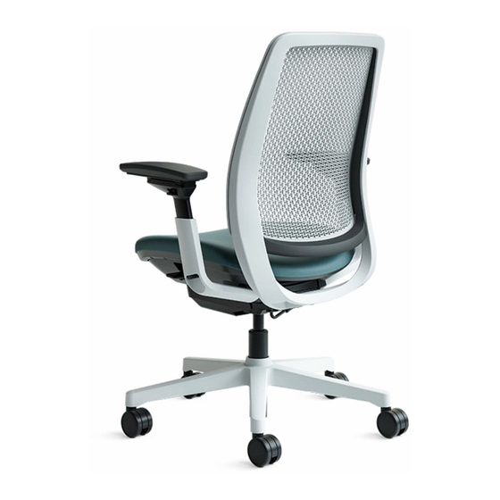
Steelcase Amia 482 Series Manual
Hide thumbs
Also See for Amia 482 Series:
- Replacement manual (9 pages) ,
- Replacement (5 pages) ,
- Installation (4 pages)
Advertisement
Table of Contents
- 1 Table of Contents
- 2 Removal & Installation of the Seat
- 3 Removal & Installation of the Arms
- 4 Removal & Installation of the Arm Cap
- 5 Removal & Installation of the Back Cushion
- 6 Removal & Installation of the Lumbar
- 7 Removal & Installation of the Back Shell
- 8 Removal & Installation of the Back Assembly
- 9 Removal & Installation of the Base
- 10 Removal & Installation of the Base Cap
- 11 Removal & Installation of the Pneumatic Cylinder
- 12 Removal & Installation of the Stool Footring
- 13 Installation of Chair Control Bumpers
- Download this manual
Table of Contents
Page
Topic
2-3
4
5
6-7
8
8
Removal & Installation of the Air Back Shellll
9
Removal & Installation of the Air Lumbar Pad
10
11-12
13
14
15
16
17-18
Removal & Installation of the Chair Control
19
If you have a problem, question, or request, call
your local dealer, or Steelcase Line 1 at
888.STEELCASE (888.783.3522)
for immediate action by people who want to help you.
(Outside the U.S.A., Canada, Mexico, Puerto Rico,
and the U.S. Virgin Islands, call: 1.616.247.2500)
Or visit our website: www.steelcase.com
© 2007 Steelcase Inc.
Grand Rapids, MI 49501
U.S.A.
Printed in U.S.A.
™
482 Amia
and Amia Air
™
Chair for Customer Service
Torx T-20 & T25
1/2" Socket
or a flat-bladed
screwdriver that is 8"
or longer
PNEUMATIC CYLINDER
REMOVAL TOOL
Page 1 of 19
939548202 Rev D
Advertisement
Table of Contents

Related Manuals for Steelcase Amia 482 Series


Summary of Contents for Steelcase Amia 482 Series
-
Page 1: Table Of Contents
Removal & Installation of the Chair Control Installation of Chair Control Bumpers If you have a problem, question, or request, call your local dealer, or Steelcase Line 1 at 888.STEELCASE (888.783.3522) for immediate action by people who want to help you. -
Page 2: Removal & Installation Of The Seat
Removal & Installation of the Seat Locate the white quick release tab located on the left hand side of the chair (as you sit in it) between the plates. REAR Lift the quick release tab (2a) while lifting the seat slide lever (2b) and sliding the seat forward &... - Page 3 Align the new seat with the chair control and engage the slots on the bottom of the seat with the tabs located on the seat bearings (3a). Slide seat fully backward while holding up on the seat slide lever (3b). SLOT ON BOTTOM TAB ON BEARING OF CHAIR...
-
Page 4: Removal & Installation Of The Arms
SCREW Removal & Installation of the Arms Follow steps on page 2 for seat removal. Remove two (2) screws on SCREW each arm. Remove old arms. Install new arms. Install two (2) screws on each arm. Torque to 25-35 in-lbs. Follow steps on page 3 for seat installation. -
Page 5: Removal & Installation Of The Arm Cap
Removal & Installation of the Arm Cap To remove arm cap, remove four (4) screws (1a) and remove cap from arm (1b). To replace arm cap, reverse steps 1a and 1b and tighten screws to 6-10 in-lbs. When installing, make sure to align the ribs on the two (2) screw bosses of the arm cap to the rear of the arm. -
Page 6: Removal & Installation Of The Back Cushion
BACK CUSHION Removal & Installation of the Back Cushion Lay chair on its side and peel the j-channel, on the back cushion, from the back assembly. Flip chair over and lift on the back cushion to remove. J-CHANNEL ON THE BACK CUSHION BACK ASSEMBLY Page 6 of 19... - Page 7 CHAIR BACK HOOKS CUSHION CHAIR BACK SHELL Place back cushion onto the chair back and slide back cushion onto the chair back by starting at the bottom (3a) and working your hands upward as CHAIR BACK CUSHION CHAIR BACK shown (3b & 3c) until installed. SHELL Lay chair on its side and install the j-channel, on the...
-
Page 8: Removal & Installation Of The Lumbar
LUMBAR Removal & Installation of the Lumbar Follow steps on page 6 for removal of the back cushion. Remove the lumbar by pulling it out. To install the lumbar, place one side of the lumbar into position in the back assembly. Then, flex the lumbar (and the wires of the lumbar) inward and place the other side into position. - Page 9 Removal the Amia Air Back Shell Remove four (4) Back Shell screws. Push bottom out (2a) and pull up on Back Shell to remove (2b). When lumbar is installed, center it between the two lower hooks. Start with Back Shell top bosses in front of Back Frame top edge (4a) and Back Shell lower tabs in front of cross bar (4b).
- Page 10 Removal & Installation of the Lumbar for Amia Air Follow steps on page 9 for removal of the Back Shell. With Back Shell removed, the Lumbar Handles can be removed from the Lumbar pad. Rotate the Handle to 45° (2a), then shift the gap to one end (2b) and rotate Handle to unsnap from Lumbar Pad (2c).
-
Page 11: Removal & Installation Of The Back Assembly
BOLT Removal & Installation of the Back Assembly Turn chair over. Remove four (4) back assembly bolts. Remove back assembly and back angle rear cover. Set back angle rear cover aside until reassembly. BACK ANGLE REAR COVER BACK ASSEMBLY Page 11 of 19 939548202 Rev D... - Page 12 BOLT Install back angle rear cover onto the edge of the chair control (4a). Insert the back assembly (4b). Secure using four (4) back assembly bolts. Tighten to 130-190 in-lbs. Turn chair over. BACK ANGLE REAR COVER BACK ASSEMBLY Page 12 of 19 939548202 Rev D...
-
Page 13: Removal & Installation Of The Base
BASE Removal & Installation of the Base Turn chair on its side and hit bottom of the cylinder with a hammer (1a) while pulling forward on the chair base (1b). Remove chair base. To install base, align base with cylinder and slide onto cylinder. Turn chair over. -
Page 14: Removal & Installation Of The Base Cap
Removal & Installation of the Base Cap Follow the steps on page 13 for base removal. Using your hands, pry the base cap off of the base (2a) and remove (2b). To install base cap, place the cap onto the base and press. Follow the steps on page 13 for base installation. -
Page 15: Removal & Installation Of The Pneumatic Cylinder
PNEUMATIC CYLINDER REMOVAL TOOL Removal & Installation of the Pneumatic Cylinder Follow steps on page 13 for base removal. Install the pneumatic cylinder removal tool (part number 879100100) on the top part of the column, as close as possible to the control. PNEUMATIC LEVER Apply lifting force to the column, with one hand. -
Page 16: Removal & Installation Of The Stool Footring
Removal & Installation of the Footring Follow steps on page 13 for base removal. Twist footring and remove. Reverse step 2 to install new footring. Follow steps on page 13 for base installation. Page 16 of 19 939548202 Rev D... - Page 17 Removal & Installation of the Chair Control Follow steps on page 11 to remove the back assembly. Follow steps on page 2 to remove the seat. Follow steps on page 4 to remove the arms. ENGINE COVER Follow steps on page 13 to remove the base.
- Page 18 To install the new chair control, begin by reversing steps 7a and 7b. Follow steps on page 15 to install the cylinder. Follow steps on page 16 to install the footring if necessary. Follow steps on page 13 to install the base. ENGINE COVER Follow steps on page 4 to install the arms.
-
Page 19: Installation Of Chair Control Bumpers
Installation of Chair Control Bumpers Refer to page 2 and remove the seat assembly from the chair. Access the chair control bumpers through the rectangular opening in the base assembly top plate. Slide bumper onto the edge of the reclining mechanism frame as shown (2a).
Need help?
Do you have a question about the Amia 482 Series and is the answer not in the manual?
Questions and answers