Table of Contents
Advertisement
Quick Links
Model CXT-DM
CXT-DM Toxic Gas Sensors
CXT-DM O2 Deficiency Sensors
Operator's Installation and Instruction Manual
Covers all Model CXT-DM Sensors
DETCON, Inc.
4055 Technology Forest Blvd, Suite 100
The Woodlands, Texas 77381
Ph.281.367.4100 / Fax 281.298.2868
www.detcon.com
December 08, 2015 • Document # 3804 • Revision 2.0
Advertisement
Table of Contents

Related Manuals for Detcon CXT-DM


Summary of Contents for Detcon CXT-DM
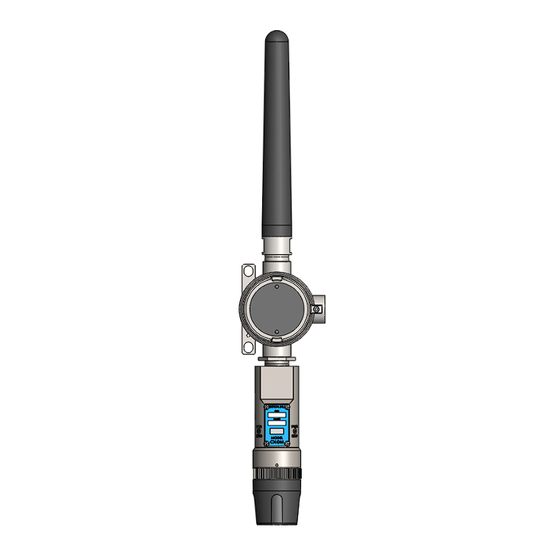
- Page 1 Model CXT-DM CXT-DM Toxic Gas Sensors CXT-DM O2 Deficiency Sensors Operator’s Installation and Instruction Manual Covers all Model CXT-DM Sensors DETCON, Inc. 4055 Technology Forest Blvd, Suite 100 The Woodlands, Texas 77381 Ph.281.367.4100 / Fax 281.298.2868 www.detcon.com December 08, 2015 • Document # 3804 • Revision 2.0...
- Page 2 Model CXT-DM This page left intentionally blank Model CXT-DM...
-
Page 3: Table Of Contents
Model CXT-DM Table of Contents Introduction ..............................1 Description ............................1 Modular Design ..........................2 1.2.1 CXT-DM Intelligent Transmitter Module ..................3 1.2.2 Field Replaceable Sensor ........................ 3 CXT Wireless Network ........................4 Battery Pack Options .......................... 4 1.4.1 Detcon’s Smart Battery Pack ......................4 1.4.2... - Page 4 Figure 10 Tri C Lithium Battery Holder ......................7 Figure 11 Approval Labels ........................... 8 Figure 12 CXT-DM Sensor with D or Smart Battery Pack Mounting Dimensions ........... 12 Figure 13 CXT-DM Sensor with Lithium Battery Pack..................13 Figure 14 Terminal Interconnect for Smart Battery Pack .................. 15 Figure 15 Magnetic Programming Tool ......................
-
Page 5: Introduction
Model CXT-DM 1. Introduction 1.1 Description Detcon Compact Wireless Sensor Model CXT-DM toxic gas and O deficiency sensors are non-intrusive wireless sensors designed to detect and monitor a wide range of toxic gases in air. The unit is designed to work as part of a wireless network of gas sensors and communication is performed via a built-in RF transceiver. -
Page 6: Modular Design
20.9% oxygen. Figure 3 Construction of Galvanic Cell 1.2 Modular Design The Model CXT-DM Sensor Assembly is completely modular and is made up of four parts (See Figure 4 for Assembly Breakaway): 1) CXT-DM Intelligent Transmitter Module (ITM) -
Page 7: Cxt-Dm Intelligent Transmitter Module
Figure 5 Functional Block Diagram 1.2.2 Field Replaceable Sensor The Detcon family of electrochemical gas sensor is field proven, plug-in sensors with over-sized gold-plated connections that eliminate corrosion problems. The sensor can be accessed and replaced in the field easily by releasing the locking screw and unthreading the Splashguard Adapter Assembly. -
Page 8: Cxt Wireless Network
CXT-DM transceivers can be deployed with less concern about physical location 1.4 Battery Pack Options The CXT-DM can be powered by an optional battery pack that enables it to be remotely mounted without the need for external cabling. Detcon offers several battery pack options. These options are factory installed. -
Page 9: D Cell Lithium Battery Pack
This battery pack provides the unit with 18 volts. The batteries are contained in a battery holder mounted in Detconꞌs aluminum explosion proof condulet. The CXT-DM sensors will operate up to 9 months before battery replacement is needed. The battery Pack and Terminal Board are housed in Detcon’s Aluminum CXT-DM Instruction Manual Rev. -
Page 10: Tri-C Lithium Battery Pack
Detconꞌs stainless steel explosion proof mini-condulet. This option offers a smaller foot print, but provides less run time than Detcon’s Smart Battery Pack. The CXT- IR sensors can operate for up to 60 days before battery replacement is needed. The addition of Detconꞌs Stainless Steel Mini Condulet provides Class I Div 1, Group C, and D ratings. -
Page 11: Figure 10 Tri C Lithium Battery Holder
Model CXT-DM Figure 10 Tri C Lithium Battery Holder CXT-DM Instruction Manual Rev. 2.0 Page 7 of 54... -
Page 12: Installation
2.1 Hazardous Locations Installation Guidelines for Safe Use NOTE: The CXT-DM assembly with strobe is not rated for Class I Division 1 or Class I Zone 1 applications. The following guidelines only apply to a CXT-DM assembly without a strobe. -
Page 13: Sensor Placement
10. These sensors pass dielectric strength of 500VRMS between circuit and enclosure for a minimum of 1 minute at a maximum test current of 5mA. 11. The CXT-DM may be used as an oxygen deficiency sensor; the CXT-DM must not be used for detecting oxygen concentrations expected to be greater than 21% 12. - Page 14 If the sensor cannot be mounted away from these conditions then make sure the Detcon Harsh Location Dust Guard accessory is used. Do not mount in locations where temperatures will exceed the operating temperature limits of the sensor.
-
Page 15: Sensor Contaminants And Interference
The CXT-DM should be vertically oriented so that the sensor points straight downward. The explosion-proof enclosure or junction box is typically mounted on a wall or pole (See Figure 12). Detcon provides a selection of standard junction boxes in both Aluminum and Stainless Steel. -
Page 16: Figure 12 Cxt-Dm Sensor With D Or Smart Battery Pack Mounting Dimensions
0.5". 23" Typ. 5.5" NPT Port " mounting holes ITM Assembly Splash Guard Adapter Splash Guard 9.5" 7.45" Figure 12 CXT-DM Sensor with D or Smart Battery Pack Mounting Dimensions CXT-DM Instruction Manual Rev. 2.0 Page 12 of 54... -
Page 17: Figure 13 Cxt-Dm Sensor With Lithium Battery Pack
Mini Condulet with Ø0.4 X 0.475" Battery Holder and mounting Batteries holes 6-32 tapped ground point ITM Assembly Splash Guard Adapter Splash Guard Figure 13 CXT-DM Sensor with Lithium Battery Pack CXT-DM Instruction Manual Rev. 2.0 Page 13 of 54... -
Page 18: Electrical Installation
However, they are not designed to provide an absolute watertight seal, especially when used in the vertical orientation. NOTE: The Detcon Warranty does not cover water damage resulting from water leaking into the enclosure. -
Page 19: Initial Start Up
Observe the following normal conditions: 1. Upon power up the sensor will scroll “CXT-DM V##.##” and will then display the current reading for about 5 seconds. A temporary upscale reading may occur as the sensor stabilizes. This upscale reading will decrease to “0”... -
Page 20: O 2 Deficiency Sensors
Splash Guard. If the wind guard was used, remove the wind guard. Initial operational tests are complete. CXT-DM toxic gas sensors are factory calibrated prior to shipment, and should not require significant adjustment on start up. However, it is recommended that a complete calibration test and adjustment be performed 16 to 24 hours after power-up. - Page 21 Model CXT-DM Material Requirements • -Detcon PN 613-120000-700 700 Series Splash Guard with integral Cal Port and with Wind Guard - • -Detcon PN 943-000006-132 Threaded Calibration Adapter • -Detcon Zero Gas: 100% N2 at fixed flow rate of 200-500cc/min a) Attach the calibration adapter to the threaded sensor housing or connect tubing to the integral cal port.
-
Page 22: Operation
While changing values inside menu items, if there is no magnet activity after 3-4 seconds the sensor will revert to the menu scroll. If the sensor is in Bump Test mode, the display will remain active. CXT-DM Instruction Manual Rev. 2.0 Page 18 of 54... -
Page 23: Operator Interface
Last Cal ## Days Sensor Life ###% Temperature ##C Alarm 1 Alarm 2 Set Detection Range Set Autospan Level Bump Test Restore Defaults Set RF Channel Alarm Settings Set Modbus ID CXT-DM Instruction Manual Rev. 2.0 Page 19 of 54... -
Page 24: Normal Operation
If a sensor has been exposed to any de-sensitizing gases, or to very high over-range combustible gas levels, re-calibration should be considered. Unless otherwise specified, span adjustment is recommended at 50% of the full scale range. CXT-DM Instruction Manual Rev. 2.0 Page 20 of 54... -
Page 25: Autozero
-Detcon PN 613-120000-700 Splash Guard with integral Cal Port and with Wind Guard. -OR- • -Detcon PN 943-000006-132 Threaded Calibration Adapter • -Detcon PN 942-001123-000 Zero Air cal gas (or use ambient air if no target gas is present). • -Detcon P/N 942-640023-100 Nitrogen 99.99% NOTE:... -
Page 26: Autospan
Detcon PN 943-000006-132 Threaded Calibration Adapter • Detcon Span Gas (See Detcon for Ordering Information). Recommended span gas is 50% of range with target gas. Other suitable span gas sources containing the target gas in air or N balance are acceptable. -
Page 27: Program Mode
Program Mode provides for adjustment of the detection range, AutoSpan Level, RF Channel, and Modbus ID. Additionally, Program Mode includes the diagnostic function “Bump Test” and “Restore Defaults”. The Program Mode menu items appear in the order presented below: View Sensor Status CXT-DM Instruction Manual Rev. 2.0 Page 23 of 54... -
Page 28: Navigating Program Mode
Co-processor firmware version The menu item appears as: “Cp App ##.##” Rf firmware version The menu item appears as: “Rf App ##.##.##” Rf Software version The menu item appears as: “Rf Sw ##.##” CXT-DM Instruction Manual Rev. 2.0 Page 24 of 54... - Page 29 The menu item appears as: “Modbus ID is ##” Serial Number The menu item appears as: “Serial Number ##.##.##”. This is the serial number for the radio embedded in the CXT-DM. RF Channel The menu item appears as: “RF Channel ##”...
-
Page 30: Set Detection Range
3.4.3 Set Detection Range The full-scale range of a CXT-DM sensor is determined at the time of order. The Plug-in Sensor is factory calibrated for this range. The range should not be changed in the field unless directed to do so by Detcon. -
Page 31: Restore Defaults
15 seconds (the display will scroll “Restore Defaults” 4 times and then return to Normal Operation). Following the execution of “Restore Defaults”, the CXT-DM will revert to its factory default settings. The default settings are: NOTE: The following must be performed in order before the sensor can be placed in operation. -
Page 32: Alarm Settings
(typically 4 repeated text scrolls), the ITM will automatically revert to Normal Operation. 3.4.9 Set Modbus ID Detcon CXT sensor can be polled serially via Modbus™ RTU. Refer to Section 4.0 for details on using the Modbus™ output feature. -
Page 33: Modbus™ Communications
CXT. By default this is turned off since it can cause issues with some controllers that do not process Modbus™ exceptions (See Section 4.2.2.4 Register – Control). The following exception codes are supported and returned when Modbus™ exceptions are enabled: CXT-DM Instruction Manual Rev. 2.0 Page 29 of 54... -
Page 34: Modbus™ Broadcast Requests
There are other exception codes defined in Modbus™ but these are the only ones used by the CXT. NOTE: When using Detcon controllers, Modbus exceptions should be turned off. 4.1.2 Modbus™ Broadcast Requests The Modbus™ broadcast request was introduced in the CXT to support commands to be executed across all CXT transceivers simultaneously. -
Page 35: Table 2 Cxt-Dm Register Map
Model CXT-DM the CXT sensor and the other for the CXT transceiver. For a more detailed description of the Register Map please contact Detcon. Table 2 CXT-DM Register Map Offset Name Comment 0000 CXT-DM-100 Device Type = 36 0001 Range... -
Page 36: Cxt Sensor Registers
– Processor Fault Bit 5 – Memory Fault Bit 4 – Reserved Bit 3 – Reserved Bit 2 – Temperature Fault Bit 1 – Auto Span Fault Bit 0 – Global Fault CXT-DM Instruction Manual Rev. 2.0 Page 32 of 54... -
Page 37: Cxt Transceiver Registers
4.2.2 CXT Transceiver Registers 4.2.2.1 Battery Info – Multiple Registers If a Detcon smart battery pack is connected to the CXT, there are five registers associated with information about that battery. The CXT utilizes the I C interface to read battery status and only one Detcon battery pack can be read per CXT. - Page 38 32 bit register and incremented each second. The last register 8210 maintains the millisecond count and will count from 0 to 999 and start over again. CXT-DM Instruction Manual Rev. 2.0 Page 34 of 54...
-
Page 39: Service And Maintenance
5.1.1 Units with 12V Smart Battery Pack The CXT-DM Sensor incorporates a ‘Low battery’ fault message which will appear as an alternating display between the current gas reading and ‘VOLT’ on the sensor display. This fault will appear when the battery voltage drops below 7.5 volts. -
Page 40: Units With Tri 'C' Sized Lithium Battery Holder
5. The orientation of batteries is marked on the inside of the cover and the holder. Remove the batteries from the battery holder. 6. Replace the batteries with the same type (Detcon P/N 360-TL5930-000). Pay close attention to the orientation of the batteries. Installing the batteries incorrectly can cause damage to the batteries, the battery holder and the unit (refer to Figure 19). -
Page 41: Replacement Of Plug-In Sensor
4. The orientation of batteries is marked on the inside of the cover and the holder. Remove the batteries from the battery holder. 5. Replace the batteries with the same type (Detcon PN 360-026500-000). It is permissible to use only Tadiran Model TL-5920 batteries. Do NOT use regular ꞌCꞌ size batteries, as this may cause damage to the sensor assembly. -
Page 42: Replacement Of Itm - Aluminum J-Box
Model CXT-DM NOTE: Only replace the plug-in sensor with an authorized CXT-DM family of gas sensors. Locking Setscrew Display Window (Bottom View) Locking Setscrew Plug in Sensor (Bottom view) Figure 21 Sensor Cell and ITM Mating 1. Use a 1/16” Allen wrench to release the locking setscrew that locks the ITM and Splashguard Adapter Assembly together (One turn will suffice - Do not remove setscrew completely). -
Page 43: Replacement Of Itm - Stainless Steel Mini Condulet
10. Re-install the battery holder in the J-box, and re-install the batteries into the housing. Replace the battery holder cover. 11. Check and/or perform Zero Calibration and Span Calibration per sections 3.3 Calibration. CXT-DM Instruction Manual Rev. 2.0 Page 39 of 54... -
Page 44: Troubleshooting Guide
• Check for obstructions affecting cal gas hitting sensor face (including being wet, blocked, or corroded). H2S sensors assemblies use CXT-DM Series Splashguard Adapter Assembly with integral filter. Clean or replace if necessary. • Replace the plug-in toxic sensor. - Page 45 • Check for obstructions affecting cal gas hitting sensor face (including being wet, blocked, or corroded). H2S sensors assemblies use CXT-DM Series Splashguard Adapter Assembly with integral filter. Clean or replace if necessary. • Replace the plug-in toxic sensor.
-
Page 46: Customer Support And Service Policy
Including all implied warranties of merchantability and fitness and the express warranties stated herein are in lieu of all obligations or liabilities on the part of Detcon Inc. for damages including, but not limited to, consequential damages arising out of, or in connection with, the performance of the product. -
Page 47: Cxt-Dm Sensor Warranty
8. CXT-DM Sensor Warranty Plug-in Sensor Warranty Detcon Inc. warrants, under normal intended use, each new plug-in sensor per the period specified in the Warranty column of Table 3 Sensor Specific Data (See section 9.2 Sensor Specific Data) and under the conditions described as follows: The warranty period begins on the date of shipment to the original purchaser. -
Page 48: Appendix
10-95% RH Continuous Duty (See Table 3 Sensor Specific Data) 0-100% RH Short-Term Duration Only Operating Pressure: Ambient ± 10% Air Velocity: 0-5 meters/second 9.1.3 Electrical Specifications Input Voltage: 7.2-30 VDC Power Consumption: 20mW (Low Power Mode) CXT-DM Instruction Manual Rev. 2.0 Page 44 of 54... -
Page 49: Mechanical Specifications (Itm Only)
371-232500-002 T90<60 <1%signal -20 to+40 20 to 95 1.5 years The last three digits of the Part Number are the range of the sensor cell. I.E. “-100” is a 100ppm range. CXT-DM Instruction Manual Rev. 2.0 Page 45 of 54... - Page 50 Sulfur Dioxide 371-555500-020 T90=20 -20 to+50 15 to 90 2 years loss/month The last three digits of the Part Number are the range of the sensor cell. I.E. “-100” is a 100ppm range. CXT-DM Instruction Manual Rev. 2.0 Page 46 of 54...
-
Page 51: Interference Table
Hydrogen Fluoride HF Toluene C Chlorine Cl Hydrogen Selenide HSe Tungsten Hexafluoride WF Chlorine Dioxide ClO Hydrogen Sulfide H Vinyl Acetate C Chlorine Trifluoride ClF Dimethyl Sulfide C Vinyl Chloride C Diborane B CXT-DM Instruction Manual Rev. 2.0 Page 47 of 54... - Page 52 415=40 415=340 415=75 415=170 275=170 0.1=0.05 yes n/d COCl 1000=0 50=0.5 100=0.01 100=<1 0.2=0.14 200=40 200=340 200=75 200=170 200=40 200=340 200=75 200=170 n/a – not applicable n/d – no data CXT-DM Instruction Manual Rev. 2.0 Page 48 of 54...
-
Page 53: Table 5 Cross Interference Table
0.2=0.15 5=yes n/d 5000=0 300=0 0.5=-0.04 0.2=0.11 5=yes n/d 300=<5 1=<0.5 200=140 200=100 200=135 200=150 200=50 200=180 200=140 200=100 200=135 200=150 200=50 200=180 n/a – not applicable n/d – no data CXT-DM Instruction Manual Rev. 2.0 Page 49 of 54... - Page 54 10=0.03 yes n/d COCl %range=0 1%=0 1=0.4 %range=0 3000=0 10=0.1 1=1.0 %range=0 3000-=0 10=1 100=0 100=0 10=<5 200=220 200=275 200=330 200=220 200=275 200=330 n/a – not applicable n/d – no data CXT-DM Instruction Manual Rev. 2.0 Page 50 of 54...
- Page 55 5=<1.5 15=-0.75 35=0 1=-.015 10=0 100%=0 1=0.7 0.3=0.03 COCl 100%=0 0.3=0 0.05=0.005 100%=0 0.05=0.005 100%=0 0.1=0.13 15=0 35=0 5=˜-5 200=415 200=275 200=415 200=275 n/a – not applicable n/d – no data CXT-DM Instruction Manual Rev. 2.0 Page 51 of 54...
- Page 56 3=4(theory) yes n/d yes n/d 5=<1 415=45 415=200 415=200 413=55 5=<2 5=-0.025 1=0.015 COCl 1=0.56 200=45 200=200 200=55 200=45 200=200 200=55 n/a – not applicable n/d – no data CXT-DM Instruction Manual Rev. 2.0 Page 52 of 54...
-
Page 57: Spare Parts, Sensor Accessories, Calibration Equipment
Model CXT-DM 9.4 Spare Parts, Sensor Accessories, Calibration Equipment Part Number Spare Parts 92C-XX0200-YYY CXT-DM Intelligent Transmitter Module for Toxic Gas Sensors (where xx=Gas Code, and YYY=Range) 371-XXXX00-XXX Replacement Plug-in sensor (Refer to Table 3 Sensor Specific Data) 500-005180-100 CXT Smart Battery Terminal Board... -
Page 58: Revision Log
Updated to add D Cell, remove Group B gases Shipping Address: 4055 Technology Forest, Suite 100, The Woodlands, Texas 77381 Mailing Address: P.O. Box 8067, The Woodlands Texas 77387-8067 www.detcon.com Phone: 888.367.4286, 281.367.4100 • Fax: 281.292.2860 • • CXT-DM Instruction Manual Rev. 2.0 Page 54 of 54...
Need help?
Do you have a question about the CXT-DM and is the answer not in the manual?
Questions and answers