Table of Contents
Advertisement
Quick Links
INSTRUCTION MANUAL
Detcon Model TP-524D
TP-524D Hydrogen Sulfide Sensor
This manual covers the following ranges:
0-20ppm, 0-50ppm, and 0-100ppm
June 05, 2018 • Document #3269 • Revision 0.8
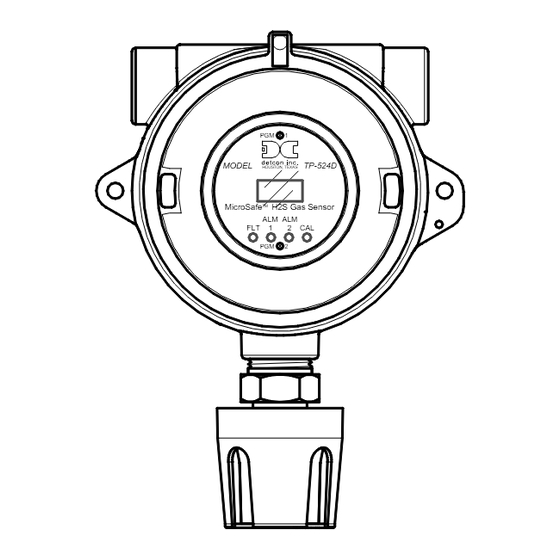
PGM
1
MODEL
TP-524D
HOUSTON, TEXAS
MicroSafe
TM
H2S Gas Sensor
ALM ALM
FLT
1
2
CAL
PGM
2
4055 Technology Forest Blvd, Suite 100,
The Woodlands, Texas 77381
Ph.281.367.4100 / Fax 281.298.2868
DETCON, Inc.
www.detcon.com
Advertisement
Table of Contents

Related Manuals for Detcon TP-524D


Summary of Contents for Detcon TP-524D
- Page 1 MODEL TP-524D HOUSTON, TEXAS MicroSafe H2S Gas Sensor ALM ALM TP-524D Hydrogen Sulfide Sensor This manual covers the following ranges: 0-20ppm, 0-50ppm, and 0-100ppm DETCON, Inc. 4055 Technology Forest Blvd, Suite 100, The Woodlands, Texas 77381 Ph.281.367.4100 / Fax 281.298.2868 www.detcon.com...
- Page 2 Model TP-524D This page left intentionally blank Model TP-524D...
-
Page 3: Table Of Contents
Fault Diagnostic/Failsafe Features ....................23 Service and Maintenance ..........................26 Troubleshooting Guide ..........................28 Customer Support and Service Policy ......................31 TP-524D Sensor Warranty ......................... 32 Appendix ..............................33 Specifications ............................ 33 Spare Parts, Sensor Accessories, Calibration Equipment ..............35 Revision Log ............................. - Page 4 Figure 8 Typical Installation ..........................8 Figure 9 Sensor Connector PCB .......................... 9 Figure 10 Magnetic Programming Tool ......................12 Figure 11 Magnetic Programming Switches ...................... 12 Figure 12 TP-524D Software Flowchart ......................14 Figure 13 Replaceable H S Sensor ........................28 List of Tables Table 1 Cross Interference Gases .........................
-
Page 5: Introduction
Model TP-524D 1. Introduction 1.1 Description Detcon Model TP-524D hydrogen sulfide sensors are non-intrusive “Smart” sensors designed to detect and monitor H S in air. Ranges of detection are 0-20ppm, 0-50ppm, and 0-100ppm. The sensor features an LED display of current reading, fault, and calibration status. The Sensor is equipped with a standard analog 4- 20mA output. -
Page 6: Modular Mechanical Design
The sensor response is reversible and results in continuous monitoring of ambient air conditions. 1.2 Modular Mechanical Design The Model TP-524D Sensor Assembly is completely modular and is made up of four parts: 1) TP-524D Plug-in Transmitter 2) Field Replaceable H... -
Page 7: Figure 4 Field Replaceable H S Sensor
S gas sensor is a field proven, replaceable type sensor. It can be accessed and replaced in the field by removing the wiring from the connector PCB, and unthreading the Sensor from the junction box. The Detcon solid state H S sensor has an infinite shelf life and is supported by a 10 year, industry-leading warranty. -
Page 8: Installation
8. These sensors meet EN60079-0, EN60079-1. Calibration/Bump Test Following Ingress Protection Events Although the Model TP-524D/624D detector models are designed for IP 66 Ingress Protection, it is a mandatory requirement from the ISA 92.00.01-2010 Performance Standard that this device requires that a gas bump test or span calibration is performed shortly after any event where the conditions of IP66 level ingresses have been presented to the detector. -
Page 9: Sensor Placement
Painting sensor assemblies is prohibited. Although the sensor is designed to be RFI resistant, it should not be mounted in close proximity to high- powered radio transmitters or similar RFI generating equipment. TP-524D Instruction Manual Rev. 0.8 Page 5 of 37... -
Page 10: Sensor Contaminants And Interference
500 = 3 Ethanol 500 = 5 NOTE: The Detcon MOS Sensor Cell can be damaged to the point of non-functioning if the unit is left off power and in the presence normal air levels of moisture for periods exceeding 8 hours. -
Page 11: Mounting Installation
The TP-524D should be vertically oriented so that the sensor points straight downward. The explosion-proof enclosure or junction box would then typically be mounted on a wall or pole (See Figure 7). Detcon provides a selection of standard junction boxes in both Aluminum and Stainless Steel. -
Page 12: Field Wiring
18" of the enclosure. Crouse Hinds type EYS2, EYD2 or equivalent are suitable for this purpose. NOTE: The Detcon Warranty does not cover water damage resulting from water leaking into the enclosure. -
Page 13: Figure 9 Sensor Connector Pcb
Observing correct polarity, terminate the 3-conductor 4-20mA field wiring (DC+, DC-, and MA) to the sensor assembly wiring in accordance with the detail shown in Figure 9. c) Trim all exposed wire leads if they are not permanently landed in the terminal block. TP-524D Instruction Manual Rev. 0.8 Page 9 of 37... -
Page 14: Initial Start Up
Upon completion of all mechanical mounting and termination of all field wiring, apply system power 24VDC (typical) and observe the following normal conditions: a) TP-524D display reads “0”, and no fault messages are flashing. b) A temporary upscale reading may occur as the sensor heats up. This upscale reading will decrease to “0”... - Page 15 Remove test gas and observe that the display decreases to “0”. Initial operational tests are complete. Detcon H S gas sensors are factory calibrated prior to shipment, and should not require significant adjustment on start up. However, it is recommended that a complete calibration test and adjustment be performed 16 to 24 hours after power-up.
-
Page 16: Operation
While changing values inside menu items, if there is no magnet activity after 3-4 seconds the sensor will revert to the menu scroll. (Exception to this is with “Signal Output Check” mode.) TP-524D Instruction Manual Rev. 0.8 Page 12 of 37... -
Page 17: Operator Interface
Alarm 2 Level Alarm 2 Ascending Alarm 2 Latching Fault Latching Set AutoSpan Level Set Range Set Heater Power Signal Output Check Restore Default Settings Alarm 1 Settings Alarm 2 Settings Fault Settings TP-524D Instruction Manual Rev. 0.8 Page 13 of 37... -
Page 18: Figure 12 Tp-524D Software Flowchart
(3) - 3 second hold from ">" prompt. dec - Decrease (10) - 10 second hold from ">" prompt. #, ##, ### - numeric values Auto Time-out - 5 seconds. Fault Latching Figure 12 TP-524D Software Flowchart TP-524D Instruction Manual Rev. 0.8 Page 14 of 37... -
Page 19: Normal Operation
NOTE 4: Span gas bottles contain 0% humidity and this ultra-low humidity condition will cause inaccurate readings when used to calibrate a sensor. To prevent this error, Detcon prescribes the use of a 24” flexible In-Line Humidifying Tube, which adds the relative humidity to the span gas. - Page 20 NOTE 1: If the sensor fails the minimum signal change criteria, a “Range Fault” will be declared and a “Fault Detected” message will be displayed alternately with the sensor’s current reading. The 4-20mA output will be taken to 0mA. TP-524D Instruction Manual Rev. 0.8 Page 16 of 37...
-
Page 21: Program Mode
Dust Cap (P/N 600-003307-000) Calibration/Bump Test Following Ingress Protection Events Although the Model TP-524D/624D detector models are designed for IP 66 Ingress Protection, it is a mandatory requirement from the ISA 92.00.01-2010 Performance Standard that this device requires that a gas bump test or span calibration is performed shortly after any event where the conditions of IP66 ingress have been presented to the detector. -
Page 22: View Sensor Status
3-4 seconds (until the display starts to scroll “Status Is”). The display will scroll the complete list of sensor status parameters sequentially: Sensor Model Type The menu item appears as: “TP-524D” Current Software Version The menu item appears as: “V X.XXZ”... -
Page 23: Set Autospan Level
Set AutoSpan Level is used to set the span gas concentration level that is being used to calibrate the sensor. This level is adjustable from 10% to 50% of selected full-scale range. The current setting can be viewed in View Program Status. The menu item appears as: “Set AutoSpan Level”. TP-524D Instruction Manual Rev. 0.8 Page 19 of 37... -
Page 24: Set Range
Set Heater Power is used to set the each H S sensor to the optimum operating temperature. This function is performed during factory calibration of each TP-524D sensor assembly, and is not necessary during installation. However, it is necessary to perform in the field if the plug-in H S sensor is replaced, mounted remotely from the Transmitter Module, or if the Restore Factory Defaults function has been executed. -
Page 25: Signal Output Check
From the “Restore Defaults” text scroll, hold the programming magnet over PGM1 until the “” prompt appears and continue to hold 10 seconds. The display will scroll “Restoring Defaults”, and then will revert to the “Restore Defaults” text scroll. TP-524D Instruction Manual Rev. 0.8 Page 21 of 37... -
Page 26: Alarm 1 And 2 Settings
3.5.7 Alarm 1 and 2 Settings The TP-524D has the ability to set alarm levels that are displayed on the front of the sensor via the LED’s ALM 1 and ALM 2. These alarm LEDs can be set as latching or non-latching. In non-latching mode, the LED is deactivated as soon as the sensor alarm condition is cleared. -
Page 27: Fault Settings
Model TP-524D 3.5.8 Fault Settings The TP-524D Fault LED can be configured to change state when the sensor experiences a fault condition. This LED can be configured as either latching or non-latching. In non-latching mode, the LED is deactivated as soon as the fault condition is cleared. - Page 28 Model TP-524D Fail-Safe/Fault Supervision Model TP-524D MicroSafe™ sensors are designed for Fail-Safe operation. If any of the diagnostic faults listed below are active, the sensor display will scroll the message “Fault Detected” every 60 seconds during normal operation. At any time during “Fault Detected” mode, holding the programming magnet over PGM1 or PGM2 for 1 second will display the active fault(s).
- Page 29 ITM display. If a Loop Fault occurs, the 4-20mA signal will be set at 0mA until the fault condition is resolved. If the 4-20mA current loop is still out of tolerance, contact Detcon at Service@detcon.com, or contact Detcon customer service.
-
Page 30: Service And Maintenance
AutoSpan Fault. Calibration/Bump Test Following Ingress Protection Events Although the Model TP-524D/624D detector models are designed for IP 66 Ingress Protection, it is a mandatory requirement from the ISA 92.00.01-2010 Performance Standard that this device requires that a gas bump test or span calibration is performed shortly after any event where the conditions of IP66 ingress have been presented to the detector. - Page 31 Re-connect the output wiring to the terminals labeled DC+, DC-, and MA on the connector PCB, g) Reconnect the black, white, blue, and yellow wires from the H S Sensor to the connector PCB. h) Reinstall the Transmitter Module, and the junction box cover. TP-524D Instruction Manual Rev. 0.8 Page 27 of 37...
-
Page 32: Troubleshooting Guide
S pull tube or other means (check MFG date on cal gas cylinder). Check for obstructions through stainless steel flame arrestor (including being wet, blocked, or corroded). Replace the H S sensor. TP-524D Instruction Manual Rev. 0.8 Page 28 of 37... - Page 33 Nuisance Alarms Check condulet for accumulated water and abnormal corrosion on terminal blocks. If nuisance alarms are happening at night suspect condensation in condulet. Add or replace Detcon’s Condensation Prevention Packet P/N 960-202200-000. Investigate the presence of other target gases that are causing cross-interference erroneous readings.
- Page 34 Perform a “Signal Output Check” sequence via Section 3.5.5 and verify 4-20mA output with Current Meter. Swap with a known-good Transmitter Module to determine if the Transmitter Module’s 4-20mA output circuit is faulty. If the 4-20mA current loop is still out of tolerance, contact Detcon at Service@detcon.com, or contact Detcon customer service. TP-524D Instruction Manual Rev.
-
Page 35: Customer Support And Service Policy
Including all implied warranties of merchantability and fitness and the express warranties stated herein are in lieu of all obligations or liabilities on the part of Detcon Inc. for damages including, but not limited to, consequential damages arising out of, or in connection with, the performance of the product. -
Page 36: Tp-524D Sensor Warranty
Should any sensor fail to perform in accordance with published specifications within the warranty period, return the defective part to Detcon, Inc., 4055 Technology Forest Blvd, Suite 100, The Woodlands, Texas 77381, for necessary repairs or replacement. -
Page 37: Appendix
CSA C22.2 No. 30-M1986 CSA C22.2 No. 142-M1987 UL No. 916 UL No.1203 FM 3810 FM 3600 FM 3615 FM 6340 Warranty: Electronics – 2 years Sensor – 10 year conditional Environmental Specifications TP-524D Instruction Manual Rev. 0.8 Page 33 of 37... - Page 38 Faults Monitored: Heater Fault, Loop Fault, Input Voltage Fault, Sensor Fault, Processor Fault, Memory Fault, Calibration Fault(s) Cable Requirements: Power/Analog – 3-wire shielded cable Maximum distance is 13,300 feet with 14 AWG TP-524D Instruction Manual Rev. 0.8 Page 34 of 37...
-
Page 39: Spare Parts, Sensor Accessories, Calibration Equipment
If the enclosure uses Detcon’s aluminum enclosure, the product will be marked as “TP-524D”. If the product uses Detcon’s 316SS enclosure, the product will be marked as “TP-524DS”. If the product uses the aluminum Killark enclosure, the product will be marked as “TP-524DK”. -
Page 40: Revision Log
Revision Date Changes made Approval 12/08/08 Initial Release 01/07/10 Changed part number for TP-524D transmitter, added desiccant caps for TP sensor. (Section8.2) Updated warranty policy, (Section 7) Updated heater power settings (Section3.5.4) Updated cross interference gas (Table 1) 04/12/11 Updated to include FM approvals related specifications 04/23/12 Updated Section 6.2 and 8.2 Field Wiring, load resistor. - Page 41 Shipping Address: 4055 Technology Forest Blvd, Suite 100, The Woodlands Texas 77381 Mailing Address: P.O. Box 8067, The Woodlands Texas 77387-8067 www.detcon.com Phone: 888.367.4286, 281.367.4100 • Fax: 281.292.2860 • • sales@detcon.com TP-524D Instruction Manual Rev. 0.8 Page 37 of 37...
Need help?
Do you have a question about the TP-524D and is the answer not in the manual?
Questions and answers