Table of Contents
Advertisement
INSTRUCTION MANUAL
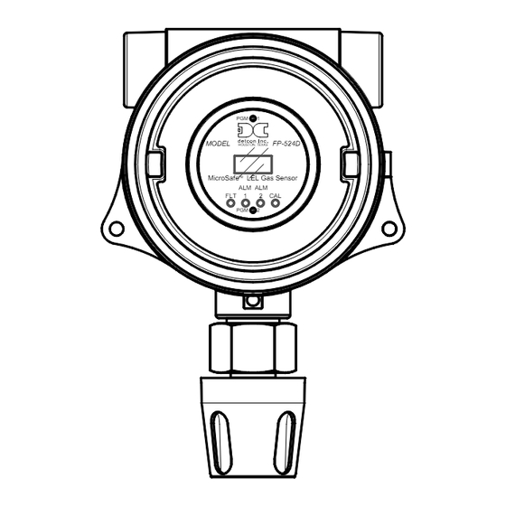
Detcon Model FP-524D
FP-524D Combustible Gas Sensor
(0 – 100% LEL)
June 06, 2018 • Document #3597 • Revision 1.6
PGM
1
MODEL
FP-524D
HOUSTON, TEXAS
MicroSafe
TM
LEL Gas Sensor
ALM ALM
FLT
1
2
CAL
PGM
2
4055 Technology Forest Blvd, Suite 100,
The Woodlands, Texas 77381
Ph.281.367.4100 / Fax 281.298.2868
DETCON, Inc.
www.detcon.com
Advertisement
Table of Contents

Related Manuals for Detcon FP-524D


Summary of Contents for Detcon FP-524D
- Page 1 Detcon Model FP-524D MODEL FP-524D HOUSTON, TEXAS MicroSafe LEL Gas Sensor ALM ALM FP-524D Combustible Gas Sensor (0 – 100% LEL) DETCON, Inc. 4055 Technology Forest Blvd, Suite 100, The Woodlands, Texas 77381 Ph.281.367.4100 / Fax 281.298.2868 www.detcon.com June 06, 2018 • Document #3597 • Revision 1.6...
- Page 2 Model FP-524D Page left intentionally blank FP-524D Instruction Manual...
-
Page 3: Table Of Contents
Fault Diagnostic/Failsafe Features ....................25 Service and Maintenance ..........................28 Troubleshooting Guide ..........................30 Customer Support and Service Policy ......................33 FP-524D Sensor Warranty .......................... 34 Appendix ..............................35 Specifications ............................ 35 Spare Parts, Sensor Accessories, Calibration Equipment ..............37 Revision Log ............................. - Page 4 Figure 3 Wheatstone Bridge ..........................2 Figure 4 Response Curves ............................ 2 Figure 5 Circuit Functional Block Diagram ......................3 Figure 6 FP-524D Transmitter Module ........................ 3 Figure 7 LEL Sensor Housing with replaceable Sensor ..................4 Figure 8 Base Connector Board ........................... 4 Figure 9 Typical Outline and Mounting Dimensions ...................
-
Page 5: Introduction
This technique is referred to as non-selective and may be used to monitor most any combustible gas. Detcon catalytic bead sensors are specifically designed to be resistant to poisons such as sulfides, chlorides, and silicones. -
Page 6: Figure 2 Sensor Cell Construction
Ambiguous readings above the LEL range dictate that alarm control logic be of the latching type, wherein alarms are held in the “ON” position until reset by operations personnel. Figure 4 Response Curves FP-524D Instruction Manual Rev. 1.6 Page 2 of 39... -
Page 7: Modular Mechanical Design
Field Replaceable Sensor The Detcon combustible gas sensor is a field proven, replaceable type sensor. It can be accessed and replaced in the field by unthreading the lower half of the sensor housing. The cell can then be unplugged and replaced. -
Page 8: Figure 7 Lel Sensor Housing With Replaceable Sensor
The base connector board is mounted in the Junction Box. The connector board includes lug-less terminal connections for incoming power and MA output, and connections for the Combustible Gas Replaceable Sensor. Wiring to LEL Sensor Customer Wiring Figure 8 Base Connector Board FP-524D Instruction Manual Rev. 1.6 Page 4 of 39... -
Page 9: Installation
NOTE: Methane and Hydrogen are lighter than air. Most other combustible gases are heavier than air. Compare the molecular weight, density, or specific gravity of the target gas(es) with that of air to determine appropriate placement. FP-524D Instruction Manual Rev. 1.6 Page 5 of 39... -
Page 10: Sensor Contaminants And Interference
2.3 Sensor Contaminants and Interference Detcon combustible gas sensors may be adversely affected by exposure to certain airborne substances. Loss of sensitivity or corrosion may be gradual if such materials are present in sufficient concentrations. The performance of the detector elements may be temporarily impaired during operation in the presence of substances described as inhibitors. -
Page 11: Mounting Installation
The FP-524D should be vertically oriented so that the sensor points straight downward. The explosion-proof enclosure or junction box would then typically be mounted on a wall or pole (See Figure 9). Detcon provides a selection of standard junction boxes in both Aluminum and Stainless Steel. -
Page 12: Figure 10 Typical Installation
18" of the enclosure. Crouse Hinds type EYS2, EYD2 or equivalent are suitable for this purpose. NOTE: The Detcon Warranty does not cover water damage resulting from water leaking into the enclosure. -
Page 13: Field Wiring
Model FP-524D 2.6 Field Wiring Detcon Model FP-524D combustible gas sensor assemblies require three conductor connections between power supplies and host electronic controller’s 4-20mA output. A 250 ohm load resistor is needed on the 4-20 mA line when it is not being used. Wiring designations are DC+, DC-, and MA (sensor signal). The maximum wire length between sensor and 24VDC source is shown in the Table below. -
Page 14: Remote Mounting Installation
This is usually true in instances where the gas sensor head must be mounted in a location that is difficult to access. Such a location creates problems for maintenance and calibration activities. Detcon provides the FP-524D sensor in a remote-mount configuration in which the sensor (Model FP-524D-RS) and the transmitter (Model FP-524D-RT) are provided in their own condulet housing and are interfaced together with a three conductor cable. -
Page 15: Bridge Voltage Adjustment
-Detcon PN 600-610000-000 Splash Guard with integral Cal Port -OR- -Detcon PN 943-000006-038 Threaded Calibration Adapter - Detcon PN 942-520124-050 Span Gas; 50% LEL methane/balance Air at fixed flow rate of 200-500cc/min. NOTE: Do not use calibration gases in Nitrogen background gas mixtures. This will cause significant reading inaccuracies. -
Page 16: Operation
3. Operation 3.1 Programming Magnet Operating Instructions The Operator Interface of the FP-524D Series gas sensors is accomplished via two internal magnetic switches located above and below the LED display (Figure 14). The two switches, labeled “PGM1” and “PGM2”, allow for complete calibration and configuration, thereby eliminating the need for area de-classification or the use of hot permits. -
Page 17: Operator Interface
Alarm 2 Latching Fault Latching Set AutoSpan Level Set Gas Factor Set Cal Factor Set Bridge Voltage Signal Output Check Restore Default Settings Alarm 1 Settings Alarm 2 Settings Fault Settings FP-524D Instruction Manual Rev. 1.6 Page 13 of 39... -
Page 18: Figure 15 Fp-524D Software Flowchart
Alarm 2 Latching dec - Decrease (10) - 10 second hold from ">" prompt. #, ##, ### - numeric values Auto Time-out - 5 seconds. Fault Latching Figure 15 FP-524D Software Flowchart FP-524D Instruction Manual Rev. 1.6 Page 14 of 39... -
Page 19: Normal Operation
-Detcon PN 613-120000-000 Splash Guard with integral Cal Port -OR- -Detcon PN 943-000006-132 Threaded Calibration Adapter -Detcon PN 942-001123-000 Zero Air cal gas or use ambient air if no combustible gas is present. NOTE: The zero gas source should have a normal background concentration of 20.9% O2. -
Page 20: Autospan
-Detcon PN 943-000006-132 Threaded Calibration Adapter -Detcon PN 942-520124-050 50% LEL Methane in balance air (recommended) or other suitable span gas containing a certified level of % LEL concentration of combustible gas in air balance. A flow fixed rate of 200-500cc/min is recommended. -
Page 21: Program Mode
The Program Mode menu items appear in the order presented below: View Sensor Status Set AutoSpan Level Set Gas Factor Set Cal Factor Set Bridge Voltage Signal Output Check Restore Default Settings FP-524D Instruction Manual Rev. 1.6 Page 17 of 39... -
Page 22: View Sensor Status
3-4 seconds (until the display starts to scroll “Status Is”). The display will scroll the complete list of sensor status parameters sequentially: Sensor Model Type The menu item appears as: “FP-524D” Current Software Version The menu item appears as: “V X.XXZ5”... - Page 23 The menu item appears as: “Alarm 2 Ascending or Descending” Alarm 2 Latching The menu item appears as: “Alarm 2 Latching or Non-Latching” Fault Latching The menu item appears as: “Fault Latching or Non-Latching” FP-524D Instruction Manual Rev. 1.6 Page 19 of 39...
-
Page 24: Set Autospan Level
3.5.3 Set Gas Factor Because of the catalytic bead sensor’s almost universal response to combustible gases, the FP-524D sensor can be configured to specifically detect any of the combustible gases listed in Table 2. This gas is referred to as the “target gas”. -
Page 25: Set Cal Factor
3.5.4 Set Cal Factor Because of the catalytic bead sensor’s almost universal response to combustible gases, the FP-524D sensor can be span calibrated with any of the combustible gases listed in Table 2 above. This specific gas is referred to as the “cal gas”. -
Page 26: Set Bridge Voltage
Operation). 3.5.5 Set Bridge Voltage Each Detcon plug-in combustible gas sensor requires a one-time setting for optimal bridge voltage. This is set automatically during the “Set Bridge Voltage” sequence. The “Set Bridge Voltage” sequence determines the required bridge voltage such that every plug-in sensor operates at exactly 200mA current. This technique provides for tremendous uniformity in sensor-to-sensor operational performance, and it is notably better than sensors that are operated on a common fixed bridge voltage platform. -
Page 27: Signal Output Check
15 seconds (the display will scroll “Restore Defaults” 4 times and then return to Normal Operation). Following the execution of “Restore Defaults”, the FP-524D will revert to its factory default settings. The default settings are: NOTE: The following must be performed in order before the sensor can be placed back into operation. -
Page 28: Alarm 1 And 2 Settings
3.5.8 Alarm 1 and 2 Settings The FP-524D has the ability to set alarm levels that are displayed on the front of the sensor via the LED’s ALM 1 and ALM 2. These alarm LEDs can be set as latching or non-latching. In non-latching mode, the LED is deactivated as soon as the sensor alarm condition is cleared. -
Page 29: Program Features
3.6.2 Fault Diagnostic/Failsafe Features Fail-Safe/Fault Supervision Model FP-524D MicroSafe™ sensors are designed for Fail-Safe operation. If any of the diagnostic faults listed below are active, the sensor display will scroll the message “Fault Detected” every 60 seconds during normal operation. At any time during “Fault Detected” mode, holding the programming magnet over PGM1 or PGM2 for 1 second will display the active fault(s). - Page 30 “Fault Detected” message to scroll once a minute on the sensor display. If a Memory Fault occurs, the 4-20mA signal will be set at 0mA until the fault condition is resolved. FP-524D Instruction Manual Rev. 1.6 Page 26 of 39...
- Page 31 ITM display. If a Loop Fault occurs, the 4-20mA signal will be set at 0mA until the fault condition is resolved. If the 4-20mA current loop is still out of tolerance, contact Detcon at Service@detcon.com, or contact Detcon customer service.
-
Page 32: Service And Maintenance
J-Box from condensing and accumulating moisture due to day-night humidity changes. This packet provides a critical function and should be replaced annually. Detcon’s PN is 960-202200-000. Replacement of Combustible Gas Sensor NOTE: It is necessary to remove power while changing the combustible gas sensor in order to maintain area classification while the junction box cover is removed. - Page 33 Re-connect the output wiring to the terminals labeled DC+, DC-, and MA on the connector PCB, g) Reconnect the black, white, blue, and yellow wires from the combustible gas sensor to the connector PCB. h) Reinstall the transmitter module, and the junction box cover. FP-524D Instruction Manual Rev. 1.6 Page 29 of 39...
-
Page 34: Troubleshooting Guide
Check validity of span gas and flow rate (check MFG date on cal cylinder). Make sure correct cal factor is set Check for obstructions through stainless steel sinter element (including being wet). Replace the plug-in sensor. Clearing Fault FP-524D Instruction Manual Rev. 1.6 Page 30 of 39... - Page 35 Nuisance Alarms Check condulet for accumulated water and abnormal corrosion on terminal blocks. If nuisance alarms are happening at night, suspect condensation in condulet. Add or replace Detcon’s Condensation Prevention Packet P/N 960-202200-000. Investigate the presence of other target gases that are causing cross-interference erroneous readings.
- Page 36 Perform a “Signal Output Check” sequence via Section 3.5.6 and verify 4-20mA output with current meter. Swap with a known-good transmitter module to determine if the transmitter module’s 4-20mA output circuit is faulty. If the 4-20mA current loop is still out of tolerance, contact Detcon at Service@detcon.com, or contact Detcon customer service. FP-524D Instruction Manual Rev.
-
Page 37: Customer Support And Service Policy
Including all implied warranties of merchantability and fitness and the express warranties stated herein are in lieu of all obligations or liabilities on the part of Detcon Inc. for damages including, but not limited to, consequential damages arising out of, or in connection with, the performance of the product. -
Page 38: Fp-524D Sensor Warranty
* Shipping point is FOB the Detcon factory. * Net payment is due within 30 days of invoice. * Detcon, Inc. reserves the right to refund the original purchase price in lieu of sensor replacement. Transmitter Module Warranty Detcon Inc. warrants, under intended normal use, each new transmitter module to be free from defects in material and workmanship for a period of two years from the date of shipment to the original purchaser. -
Page 39: Appendix
-40°C to +75°C Operating Humidity: 0-100% RH (Non-condensing) Operating Pressure: Ambient ± 10% Electrical Specifications Input Voltage: 12-28 VDC Power Consumption: Normal operation = 68mA (<1.7 watt); Maximum = 87mA (2 watts) FP-524D Instruction Manual Rev. 1.6 Page 35 of 39... - Page 40 Mechanical Specifications Length: 8 inches (200mm), including Splashguard Width: 5.5 inches (140mm) Weight: 2.7lbs (3.4Kg) Mechanical Connection: ¾” Male NPT threaded connection Electrical Connection: three 14 gauge (maximum) wire terminal landings FP-524D Instruction Manual Rev. 1.6 Page 36 of 39...
-
Page 41: Spare Parts, Sensor Accessories, Calibration Equipment
Model FP-524D 8.2 Spare Parts, Sensor Accessories, Calibration Equipment Part Number Spare Parts 925-5254D0-100 FP-524D Plug-in Transmitter Module 370-201600-000 Replacement Plug-in Sensor (Uses p/n 365-037020-160 in shipping container) 600-02056-0 FP-P Plug-in Hsg Threaded Insert 316SS 612-820000-000 Replacement LEL sensor housing (includes threaded insert) -
Page 42: Revision Log
Updated Section 2.6 Field Wiring, load resistor. 10/31/13 Added setting LED Alarm Levels 04/22/14 Removed duplicate note in Section 3.4.2 12/06/17 Updated Electrical Classification Approval Temperatures 06/06/18 Updated Conduit Seal in Section 2.5 FP-524D Instruction Manual Rev. 1.6 Page 38 of 39... - Page 43 Shipping Address: 4055 Technology Forest Blvd, Suite 100, The Woodlands Texas 77381 Mailing Address: P.O. Box 8067, The Woodlands Texas 77387-8067 www.detcon.com Phone: 888.367.4286, 281.367.4100 • Fax: 281.292.2860 • • sales@detcon.com FP-524D Instruction Manual Rev. 1.6 Page 39 of 39...
Need help?
Do you have a question about the FP-524D and is the answer not in the manual?
Questions and answers