Table of Contents
Advertisement
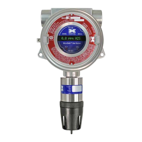
Detcon Model Series
DM-500IS OLED
Explosion Proof and Intrinsically Safe Toxic Gas Sensors
Operator's Installation and Instruction Manual
DETCON, Inc.
4055 Technology Forest Blvd. Suite 100,
The Woodlands, Texas 77381
Ph.281.367.4100 / Fax 281.298.2868
www.detcon.com
August 17, 2015 • Document #4517 • Revision 0.1
Advertisement
Table of Contents

Related Manuals for Detcon DM-500IS OLED Series


Summary of Contents for Detcon DM-500IS OLED Series
- Page 1 Detcon Model Series DM-500IS OLED Explosion Proof and Intrinsically Safe Toxic Gas Sensors Operator’s Installation and Instruction Manual DETCON, Inc. 4055 Technology Forest Blvd. Suite 100, The Woodlands, Texas 77381 Ph.281.367.4100 / Fax 281.298.2868 www.detcon.com August 17, 2015 • Document #4517 • Revision 0.1...
- Page 2 DM-500IS This page left intentionally blank DM-500IS Instruction Manual...
-
Page 3: Table Of Contents
DM-500IS Table of Contents Description..............................2 Sensor Technology ..........................2 Universal Microprocessor Control Transmitter Circuit................ 3 Base Connector Board.......................... 3 Explosion Proof Enclosure........................3 Principle Of Operation..........................4 Application ............................... 5 Sensor Placement/Mounting......................... 5 Interference Data ..........................5 Interference Gas List ..........................6 Interference Gas Table (page 1 of 5).................... - Page 4 Table 5 IS Sensor Head / Plug-in Replacement Sensor Cell................28 Shipping Address 4055 Technology Forest Blvd. Suite 100,., The Woodlands Texas 77381 Mailing Address: P.O. Box 8067, The Woodlands Texas 77387-8067 www.detcon.com Phone: 888.367.4286, 281.367.4100 • Fax: 281.292.2860 • •...
-
Page 5: Table 1 Model #, Gas Name And Symbol
DM-500IS This manual covers the following Models... Table 1 Model #, Gas Name and Symbol Model # Gas Name Symbol DM-500-C2H3O Acetaldehyde C2H3O DM-500-C2H2 Acetylene C2H2 DM-500-C3H3N Acrylonitrile C3H3N DM-500-NH3 (-20°C) Ammonia DM-501-NH3 (-40°C) Ammonia DM-502-NH3 Ammonia (continuous exposure) DM-500-AsH3 Arsine AsH3 DM-500-Br2... -
Page 6: Description
DM-500IS 1.0 Description Detcon MicroSafeTM Model DM-500IS, toxic sensors are non-intrusive “Smart” sensors designed to detect and monitor for toxic gas in the ppm range. One of the primary features of the sensor is its method of automatic calibration which guides the user through each step via instructions displayed on the OLED Display The sensor features LED indicators for FAULT and CAL status and is equipped with a standard analog 4-20 mA output. -
Page 7: Universal Microprocessor Control Transmitter Circuit
DM-500IS Universal Microprocessor Control Transmitter Circuit The control circuit is microprocessor based and is packaged as a universal plug-in field replaceable module, facilitating easy replacement and minimum down time. The universality includes the ability to set it for any range concentration and for any gas type. These gas and range settings must be consistent with the IS Sensor Head it is mated with. -
Page 8: Principle Of Operation
DM-500IS The sensor housing section employs an Intrinsically Safe Barrier circuit which allows for the safe usage of plastic housing materials in the lower section. This design benefit avoids the requirement for stainless steel flame arrestors which reduce the sensitivity and response time to “active” gas species such as NH3, CL2, CLO2, and HCL...etc. -
Page 9: Application
Each page lists all Model Numbers but 5 pages are necessary to list all interfering gases, thus each page is a repeat of the full line of Detcon sensors. Be sure to reference each page to ascertain the full listing of interfering gases for a particular sensor. -
Page 10: Interference Gas List
DM-500IS Interference Gas List Gas Name Symbol Gas Name Symbol Acetaldehyde C2H3O Hydrocarbons C-H’s Acetylene C2H2 Hydrocarbons (unsaturated) C-H’s (u) Acrylonitrile C3H3N Hydrogen Alcohols Alcohols Hydrogen Bromide Amines Amines Hydrogen Chloride Ammonia Hydrogen Cyanide Arsenic Trifluoride AsF3 Hydrogen Fluoride Arsenic Pentafluoride AsF5 Hydrogen Selenide Arsine... -
Page 11: Interference Gas Table
DM-500IS Interference Gas Table (page 1 of 5) NOTE: Reference the listing in Table 1 to match model number with gas name. Reference the listing in section 3.3 to match the interfering gas symbol with the gas name. Model Number C2H30 C2H2 C3H3N Alcohols Amines... - Page 12 DM-500IS Interference Gas Table (page 2 of 5) Model Number CL02 CLF3 B2H6 C2H6S Si2H6 C3H5OCL C2H5OH DM-500IS-C2H3O 40=140 40=100 40=135 40=150 40=50 40=180 DM-500IS-C2H2 340=140 340=100 340=135 340=150 340=50 340=180 DM-500IS-C3H3N 75=140 75=100 75=135 75=150 75=50 75=180 DM-500IS-NH3 (-20°C) 5000=0 1000=0 0.1=0...
- Page 13 DM-500IS Interference Gas Table (page 3 of 5) Model Number C2H4 C2H4O CH2O GeH4 N2H4 C-H’s C-H’s (U) DM-500IS-C2H3O 40=220 40=275 40=330 DM-500IS-C2H2 340=220 340=275 340=330 DM-500IS -C3H3N 75=220 75=275 75=330 DM-500IS-NH3 (-20°C) %range=0 1%=0 10=0 DM-501IS-NH3 (-40°C) yes n/d %range=0 1000=35 n/d yes n/d 10 = -18 n/d...
- Page 14 DM-500IS Interference Gas Table (page 4 of 5) Model Number C3H8O CH3OH C4H8O CH3SH COCL2 DM-500IS-C2H3O 40=415 40=275 DM-500IS-C2H2 340=415 340=275 DM-500IS -C3H3N 75=415 75=275 DM-500IS-NH3 (-20°C) 0.1=0 10=0 100%=0 DM-501IS-NH3 (-40°C) 14=18 yes n/d 100%=0 10 = -5 DM-502IS-NH3 (CE) 15=30 35=6 5 = -1...
- Page 15 DM-500IS Interference Gas Table (page 5 of 5) Model Number SiH4 SiF4 C4H8S C4H4S C6H5CH3 C4H6O2 C2H3CL C2H5SH C6H5CH3 DM-500IS-C2H3O 40=45 40=200 40=200 40=55 DM-500IS-C2H2 340=45 340=200 340=200 340=55 DM-500IS -C3H3N 75=45 75=200 75=200 75=55 DM-500IS-NH3 300=0 (-20°C) DM-501IS-NH3 0.3=0 yes n/d (-40°C) DM-502IS-NH3 (CE)
-
Page 16: Specifications
DM-500IS 4.0 Specifications Method of Detection Electrochemical Cell Electrical Classification CSA-NRTL (US OSHA) approved* Class 1; Groups B, C, D; Div. 1. Input Voltage 11.5-28 VDC Power Consumption Normal operation = 29.5 mA @ 24VDC Maximum 50mA @ 24VDC Maximum 70mA @ 11.5VDC Output Linear 4-20 mA DC Repeatability... -
Page 17: Installation
Field Wiring Table (4-20 mA output) Detcon Model DM-500IS toxic gas sensor assemblies require three conductor connection between power supplies and host electronic controllers. Wiring designators are + (DC), – (DC), and mA (sensor signal). Maximum single conductor resistance between sensor and controller is 10 ohms. Maximum wire size for termination in the sensor assembly terminal board is 14 gauge. -
Page 18: Figure 7 Typical Installation
DM-500IS Density - Placement of sensors relative to the density of the target gas is such that sensors for the detection of heavier than air gases should be located within 2-4 feet of grade as these heavy gases will tend to settle in low lying areas. -
Page 19: Local Electrical Codes
DM-500IS Local Electrical Codes Sensor and transmitter assemblies should be installed in accordance with all local electrical codes. Use appropriate conduit seals. Drains & breathers are recommended. The sensor assemblies are CSA-NRTL approved for Class I; Groups B, C, D; Div. 1 environments. Installation Procedure 3/4"... -
Page 20: Remote Mounting Applications
This is usually true in instances where the gas sensor head must be mounted in a location that is difficult to access. Such a location creates problems for maintenance and calibration activities. Detcon provides the DM-500IS sensor in a remote-mount configuration in which the sensor (Model DM-500IS-RS) and the transmitter (Model DM-500IS-RT) are provided in their own condulet housing and are interfaced together with a three conductor shielded cable. -
Page 21: Startup
Remove the test gas and observe that the display decreases to “0 PPM”. Initial operational tests are complete. Detcon toxic gas sensors are pre-calibrated prior to shipment and will, in most cases, not require significant adjustment on start up. However, it is recommended that a complete calibration test and adjustment be performed within 24 hours of installation. -
Page 22: Operating Software & Magnetic Interface
DM-500IS 7.0 Operating Software & Magnetic Interface Operating software is menu listed with operator interface via the two magnetic program switches located under the face plate. The two switches are referred to as “PGM 1” and “PGM 2”. The menu list consists of 3 items which include submenus as indicated below. -
Page 23: Programming Magnet Operating Instructions
DM-500IS Programming Magnet Operating Instructions Operator interface to MicroSafeTM gas detection products is via magnetic switches located behind the transmitter face plate. DO NOT remove the glass lens cover to calibrate or change programming parameters. Two switches labeled “PGM 1” and “PGM 2” allow for complete calibration and programming without removing the enclosure cover, thereby eliminating the need for area de-classification or the use of hot permits. -
Page 24: Software Flow Chart
Figure 13 Software Flow Chart 9.0 Calibration Material Requirements Detcon PN 327-000000-000 MicroSafeTM Programming Magnet Detcon PN 943-000006-132 Calibration Adapter Span gas containing the target gas in air or nitrogen. The target gas concentration is recommended at 50% of range (which is the factory default) at a controlled flow rate of 500 ml/min. -
Page 25: Calibration Procedure - Span
DM-500IS a. Enter the calibration menu by holding the programming magnet stationary over “PGM 1” (see Figure 12) for 3 seconds until the display reads “1-ZERO 2-SPAN” then withdraw the magnet. Note that the “CAL” LED is on. b. Next, enter the zero menu by holding the magnet stationary over “PGM 1” for 3 seconds until the display reads: “SETTING ZERO”, then withdraw the magnet. -
Page 26: Additional Notes
DM-500IS concentration. The display reads “APPLY xxPPM xxx” The x’s here will indicate the actual concentration requested. g. Apply the calibration test gas at a flow rate of 500 milliliters per minute. As the sensor signal changes, the display will change to “AutoSpan xxPPM”. The “xx” part of the reading indicates the actual gas reading which will increase until the sensor stabilizes. -
Page 27: Program Features
If new data points cannot successfully be stored to memory the display will indicate: “MEMORY FAULT”. Fail-Safe/Fault Supervision Detcon MicroSafeTM sensors are programmed for fail-safe operation. All fault conditions will illuminate the fault LED, and cause the display to read its corresponding fault condition: “ZERO FAULT”, “SENSOR DM-500IS Instruction Manual Rev 0.1... -
Page 28: Universal Transmitter Feature (Re-Initialization)
The Model DM500IS uses a universal transmitter design that allows the transmitter to be set up for any target gas and any toxic concentration range. The original transmitter set-up is done at Detcon Inc. as part of the sensor test and calibration procedure, but it may also be changed in the field if necessary. The Universal Transmitter feature is a significant convenience to the user because it allows hardware flexibility and minimizes the spare parts requirements to handle unexpected transmitter failures of different gas/ranges. -
Page 29: Trouble Shooting
Noisy Sensor (continuous drift) or suddenly Spiking Probable Cause: Unstable power source, inadequate grounding, Inadequate RFI protection. 1. Verify power Source output and stability. 2. Contact Detcon for assistance in optimizing shielding and grounding. 3. Add RFI Protection accessory available from Detcon. Reporting “ERROR @ XXXXXXX”... - Page 30 DM-500IS 1. Reinitialize unit by plugging in transmitter and the swiping the magnet over PGM1 while “Universal Transmitter” is displayed. Scroll through and select the correct gas type and range (see section 12.0). Make sure all customer specific settings are re-entered after “re-initialization”. DM-500IS Instruction Manual Rev 0.1 Page 26 of 30...
-
Page 31: Spare Parts List
DM-500IS 14.0 Spare Parts List 943-000006-132 Calibration Adapter 500-005065-007 Connector board 327-000000-000 Programming Magnet 897-850901-010 Aluminum Condulet 897-850901-316 Stainless Steel Condulet 960-202200-000 Condensation prevention packet (replace annually). 925-9954S0-000 DM-5xx Series Universal Plug-in Control Circuit w/OLED 925-8454S0-04P* DM-5xx-H2 LEL range Series Universal Plug-in Control Circuit w/OLED * The H2 LEL range transmitter is not universal but is discrete to Hydrogen in the 0-4% by volume range. -
Page 32: Table 5 Is Sensor Head / Plug-In Replacement Sensor Cell
DM-500IS Table 5 IS Sensor Head / Plug-in Replacement Sensor Cell Model Number GasName IS Sensor Head Plug-in Replacement Sensor Cell DM-500IS-C2H3O Acetaldehyde 394-12EA00-Range 370-12EA00-000 DM-500IS-C2H2 Acetylene 394-12EG00-Range 370-12EG00-000 DM-500IS-C3H3N Acrylonitrile 394-12EM00-Range 370-12EM00-000 DM-500IS-NH3 (-20°C) Ammonia 394-171700-Range 370-171700-000 DM-501IS-NH3 (-40°C) Ammonia 394-151500-Range 370-151500-000... -
Page 33: Warranty
DM-500IS 15.0 Warranty Detcon, Inc., as manufacturer, warrants each new electrochemical toxic gas plug-in sensor cell, for a specified period under the conditions described as follows: The warranty period begins on the date of shipment to the original purchaser and ends after the specified period as listed in the table in Section 4.0. The sensor cell is warranted to be free from defects in material and workmanship. -
Page 34: Revision History
Update wiring of Sensor and Remote Sensor, update Spare Parts Shipping Address 4055 Technology Forest Blvd. Suite 100,., The Woodlands Texas 77381 Mailing Address: P.O. Box 8067, The Woodlands Texas 77387-8067 www.detcon.com Phone: 888.367.4286, 281.367.4100 • Fax: 281.292.2860 • •...
Need help?
Do you have a question about the DM-500IS OLED Series and is the answer not in the manual?
Questions and answers