Table of Contents
Advertisement
Quick Links
INSTRUCTION MANUAL
Detcon Model DM-700
DM-700 Toxic Gas Sensors
DM-700 O
Deficiency Sensors
2
This manual covers all ranges of electrochemical and O
deficiency sensors
2
offered in the Detcon Product Line
DETCON, Inc.
4055 Technology Forest Blvd.,
The Woodlands, Texas 77381
Ph.281.367.4100 / Fax 281.298.2868
www.detcon.com
June 05, 2018 • Document #3207 • Revision 5.1
Advertisement
Table of Contents

Related Manuals for Detcon DM-700


Summary of Contents for Detcon DM-700
- Page 1 DM-700 Toxic Gas Sensors DM-700 O Deficiency Sensors This manual covers all ranges of electrochemical and O deficiency sensors offered in the Detcon Product Line DETCON, Inc. 4055 Technology Forest Blvd., The Woodlands, Texas 77381 Ph.281.367.4100 / Fax 281.298.2868 www.detcon.com...
- Page 2 Model DM-700 Page intentionally blank Shipping Address: 4055 Technology Forest Blvd., The Woodlands Texas 77381 Mailing Address: P.O. Box 8067, The Woodlands Texas 77387-8067 www.detcon.com Phone: 888.367.4286, 281.367.4100 • Fax: 281.292.2860 • • sales@detcon.com Model DM-700...
- Page 3 Visual Inspection ..........................31 Condensation Prevention Packet....................... 31 Replacement of Intelligent Plug-in Sensor ..................31 Replacement of ITM ......................... 32 Replacement of DM-700 Sensor Assembly..................33 Troubleshooting Guide..........................34 Customer Support and Service Policy ......................37 Warranty Notice..........................37 DM-700 Sensor Warranty ..........................38 Appendix ..............................39...
-
Page 4: Table Of Contents
Figure 13 Sensor Wire Connections........................12 Figure 14 Magnetic Programming Tool ......................15 Figure 15 Magnetic Programming Switches ...................... 15 Figure 16 DM-700 Software Flowchart ......................17 Figure 17 Sensor Assembly..........................31 Figure 18 Sensor Cell and ITM Mating ......................32 Figure 19 Sensor Cell and ITM Mating ...................... - Page 5 Model DM-700 Shipping Address: 4055 Technology Forest Blvd., The Woodlands Texas 77381 Mailing Address: P.O. Box 8067, The Woodlands Texas 77387-8067 www.detcon.com Phone: 888.367.4286, 281.367.4100 • Fax: 281.292.2860 • • sales@detcon.com Model DM-700...
-
Page 7: Figure 1 Construction Of Electrochemical Toxic Sensor
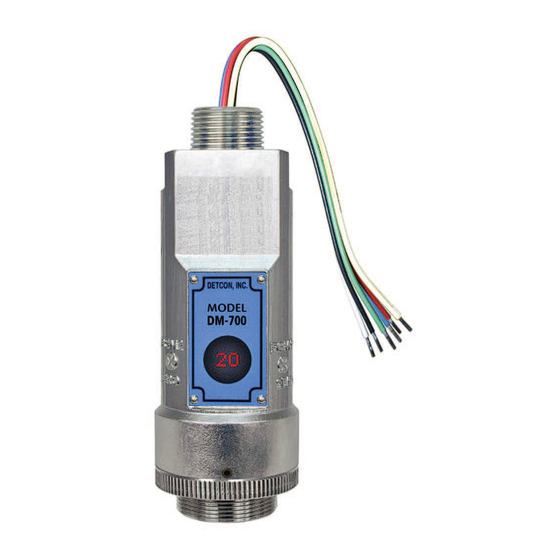
Model DM-700 1. Introduction 1.1 Description Detcon Model DM-700 toxic gas and O deficiency sensors are non-intrusive “Smart” sensors designed to detect and monitor a wide range of toxic gasses in air. Ranges of detection for toxic gasses are from 0-1ppm up to 0-10,000ppm. Ranges for O deficiency are 0-100ppm up to 0-25% by volume. -
Page 8: Figure 2 Construction Of Galvanic Cell
The DM-700 Intelligent Transmitter Module (ITM) is a fully encapsulated microprocessor-based package that is universal in design and will accept any Detcon intelligent plug-in electrochemical gas sensor. The ITM design uses an internal intrinsically safe barrier circuit that lifts the requirement for use of flame arrestors to achieve Class 1, Division 1 (Zone1) area classification. -
Page 9: Figure 4 Sensor Assembly Front View
Locking Set-Screw Figure 4 Sensor Assembly Front View 1.3 Modular Mechanical Design The Model DM-700 Sensor Assembly is completely modular and is made up of four parts (See Figure 5 for Assembly Break-away): 1) DM-700 Intelligent Transmitter Module (ITM) 2) Intelligent Plug-in Sensor (varies by gas type and range) 3) Model DM-700 Splash Guard Adapter 4) Splash Guard. -
Page 10: Figure 6 Intelligent Plug-In Sensor
The sensor can be accessed and replaced in the field very easily by releasing the locking setscrew and unthreading the Splashguard Adapter. Detcon’s family of toxic sensors have a long shelf life and are supported by an industry- leading warranty. -
Page 11: Figure 7 Atex Approval Label
9. Do not operate the sensor outside the stated operating limits for voltage supply. 10. The sensor power supply common (black wire) must be referenced to the metal enclosure body (ground) during installation. DM-700 Instruction Manual Rev. 5.1 Page 5 of 51... - Page 12 Improper sensor orientation may result in false readings and permanent sensor damage. Additional Placement Considerations The sensor should not be positioned where it may be sprayed or coated with surface contaminating substances. Painting sensor assemblies is prohibited. DM-700 Instruction Manual Rev. 5.1 Page 6 of 51...
-
Page 13: Table 6 Cross Interference Table
2.4 Mounting Installation The DM-700 sensor assembly is designed to be threaded into a ¾” Female NPT fitting of a standard cast metal, Explosion-Proof Enclosure or Junction Box. Thread the sensor up until tight (5 turns is typically expected) and until the display is pointed in the direction that sensor will normally be viewed and accessed. -
Page 14: Figure 8 Outline And Mounting Dimensions (Sensor Assembly Only)
3/4" NPT Ø0.265" Mounting Holes 8-32 Thread Ground Point Explosion Proof Enclosure Junction-Box (Detcon's SS Junction-Box shown) 12.7" Use Spacers to move the J-Box Typ. and Sensor Assembly away from the wall at least 0.25-0.5" to allow access to Sensor. -
Page 15: Figure 10 Outline And Mounting Dimensions (Aluminum Junction Box)
8-32 Thread Ground Point Ø0.4" x .475" Mounting Holes Explosion Proof Enclosure Junction-Box 11.2" (Detcon's Mini SS Junction-Box shown) Typ. Sensor Assembly Splash Guard 2.125" Figure 11 Outline and Mounting Dimensions (Mini Stainless Steel Junction Box) DM-700 Instruction Manual Rev. 5.1...
Need help?
Do you have a question about the DM-700 and is the answer not in the manual?
Questions and answers