Table of Contents
Advertisement
INSTRUCTION MANUAL
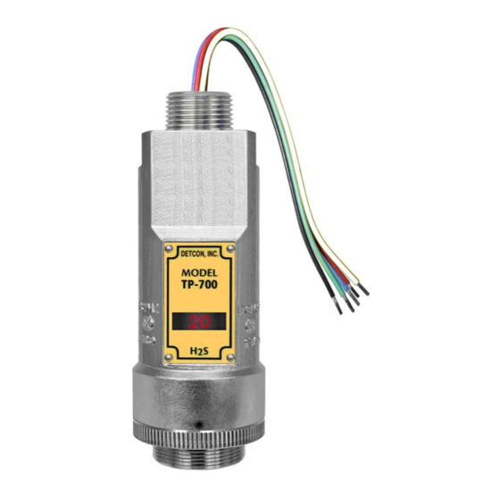
Detcon Model TP-700
TP-700 Hydrogen Sulfide Sensor
This manual covers the following ranges:
0-20ppm, 0-50ppm, 0-100ppm and 0-200ppm
DETCON, Inc.
.,
4055 Technology Forest Blvd
The Woodlands, Texas 77381
Ph.281.367.4100 / Fax 281.298.2868
www.detcon.com
June 05, 2018 • Document #3150 • Revision 4.1
Advertisement
Table of Contents

Subscribe to Our Youtube Channel
Related Manuals for Detcon TP-700


Summary of Contents for Detcon TP-700
- Page 1 INSTRUCTION MANUAL Detcon Model TP-700 TP-700 Hydrogen Sulfide Sensor This manual covers the following ranges: 0-20ppm, 0-50ppm, 0-100ppm and 0-200ppm DETCON, Inc. 4055 Technology Forest Blvd The Woodlands, Texas 77381 Ph.281.367.4100 / Fax 281.298.2868 www.detcon.com June 05, 2018 • Document #3150 • Revision 4.1...
- Page 2 Model TP-700 This page left intentionally blank Model TP-700...
-
Page 3: Table Of Contents
Condensation Prevention Packet ....................... 29 Replacement of Plug-in H S Sensor ....................29 Replacement of ITM ......................... 30 Replacement of TP-700 Sensor Assembly ..................31 Replacement of the Bottom Housing ....................31 Troubleshooting Guide ..........................32 Customer Support and Service Policy ......................35 Warranty Notice .......................... - Page 4 Figure 11 Sensor Wire Connections ........................11 Figure 12 Magnetic Programming Tool ......................14 Figure 13 Magnetic Programming Switches ...................... 14 Figure 14 TP-700 Software Flowchart ....................... 16 Figure 15 Sensor Assembly ..........................29 Figure 16 Sensor PCB ............................32 List of Tables Table 1 Cross Interference Gases .........................
-
Page 5: Introduction
Model TP-700 1. Introduction 1.1 Description Detcon Model TP-700 hydrogen sulfide sensors are non-intrusive “Smart” sensors designed to detect and monitor H S in air. Ranges of detection are 0-20ppm, 0-50ppm, 0-100ppm, and 0-200ppm. The sensor features an LED display of current reading, fault and calibration status. -
Page 6: Modular Mechanical Design
S Sensor Figure 2 Sensor Assembly Front View 1.3 Modular Mechanical Design The Model TP-700 Sensor Assembly is completely modular and is made up of four parts (See Figure 3 for Assembly Break-away): 1) TP-700 Intelligent Sensor Module (ITM) 2) Field Replaceable Plug-in H... -
Page 7: Plug-In Replaceable Sensor
S gas sensor is a field proven, plug-in replaceable type sensor with over-sized gold- plated connections that eliminate corrosion problems. It can be accessed and replaced in the field very easily by releasing the locking screw and unthreading the housing bottom. The Detcon solid state H S sensor has an infinite shelf life and is supported by a 10 year, industry-leading warranty. -
Page 8: Installation
8. Do not operate the sensor outside of the stated operating temperature limits. 9. Do not operate the sensor outside the stated operating limits for voltage supply. 10. These sensors meet EN60079-0:2012, EN60079-1:2007. TP-700 Instruction Manual Rev. 4.1 Page 4 of 42... -
Page 9: Sensor Placement
Painting sensor assemblies is prohibited. Although the sensor is designed to be RFI resistant, it should not be mounted in close proximity to high-powered radio transmitters or similar RFI generating equipment. TP-700 Instruction Manual Rev. 4.1 Page 5 of 42... -
Page 10: Sensor Contaminants And Interference
500 = 3 Ethanol 500 = 5 NOTE: The Detcon MOS Sensor Cell can be damaged to the point of non-functioning if the unit is left off power and in the presence normal air levels of moisture for periods exceeding 8 hours. -
Page 11: Mounting Installation
2.4 Mounting Installation The TP-700 sensor assembly is designed to be threaded into a ¾” Female NPT fitting of a standard cast metal, Explosion-Proof Enclosure or Junction Box. Thread the sensor up until tight (5 turns is typically expected) and until the display is pointed in the direction that sensor will normally be viewed and accessed. -
Page 12: Figure 7 Outline And Mounting Dimensions (Stainless Steel Junction Box)
4" 3/4" NPT Ø0.265" Mounting Holes 8-32 Thread Ground Point Explosion Proof Enclosure Junction-Box (Detcon's SS Junction-Box shown) 12.5" Use Spacers to move the J-Box Typ. and Sensor Assembly away from the wall at least 0.25-0.5" detcon inc. MODEL to allow access to Sensor. -
Page 13: Electrical Installation
Figure 9 Outline and Mounting Dimensions (Mini Stainless Steel Junction Box) When mounting on a pole, secure the Junction Box to a suitable mounting plate and attach the mounting plate to the pole using U-Bolts. (Pole-Mounting brackets for Detcon J-box accessories are available separately.) 2.5 Electrical Installation The Sensor Assembly should be installed in accordance with local electrical codes. -
Page 14: Field Wiring
NOTE: Any unused ports should be blocked with suitable ¾” male NPT plugs. Detcon Supplies one ¾” NPT male plug with their accessory J-box enclosures. If connections are other than ¾”... -
Page 15: Figure 11 Sensor Wire Connections
Modbus RS-485 to Modbus RS-485 to next Device Host Control Device Install a 100-250 Ohm resistor if the 4-20mA output is not used Wiring to Sensor Assembly Figure 11 Sensor Wire Connections TP-700 Instruction Manual Rev. 4.1 Page 11 of 42... -
Page 16: Initial Start Up
11.5-30VDC (24VDC typical) and observe the following normal conditions: a) TP-700 display reads “0”, and no fault messages are flashing. b) A temporary upscale reading may occur as the sensor heats up. This upscale reading will decrease to “0”... -
Page 17: Initial Operational Tests
After a warm up period of 1 hour, the sensor should be checked to verify sensitivity to H S gas. Material Requirements • Detcon PN 613-120000-700 700 Series Splash Guard with integral Cal Port -OR- • Detcon PN 943-000006-132 Threaded Calibration Adapter •... -
Page 18: Operation
While changing values inside menu items, if there is no magnet activity after 3-4 seconds the sensor will revert to the menu scroll. (Exception to this is with “Signal Output Check” mode.) TP-700 Instruction Manual Rev. 4.1 Page 14 of 42... -
Page 19: Operator Interface
Sensor Heater Power Sensor Heater Voltage Raw Sensor Resistance mA Output Input Voltage Supply Sensor Temperature Set AutoSpan Level Set Range Set Serial ID Set Heater Power Signal Output Check Restore Default Settings TP-700 Instruction Manual Rev. 4.1 Page 15 of 42... -
Page 20: Normal Operation
- Decrease Sensor Temp XX C #, ##, ### - numeric values Figure 14 TP-700 Software Flowchart 3.3 Normal Operation In normal operation, the ITM Display continuously shows the current sensor reading, which will normally appear as “ 0 ”. Once every minute, the LED display will flash the sensor’s units of measure and the gas type (i.e. ppm S). -
Page 21: Calibration Mode (Autospan)
(available from General Monitors) that has thread adapter to connect to the TP-700. The adapter cover is Detcon P/N 943-000GMI-CAP. Remove the Detcon Splashguard and connect the adapter cover firmly in place. Attach the ampoule breaking cup firmly to the cover with ampoule installed and follow the balance of the instructions for breaking ampoule and executing AutoSpan. - Page 22 AutoSpan sequence. The ITM will continue to report a “Stability Fault” and will not clear the fault until a successful AutoSpan is completed. If the sensor passes the stability check, the ITM reports a series of messages: “AutoSpan Complete” “Sensor Life XXX%” “Remove Span Gas” TP-700 Instruction Manual Rev. 4.1 Page 18 of 42...
-
Page 23: Program Mode
At the conclusion of the text scroll the arrow prompt (“►” for PGM2 or “◄” for PGM1) will appear, immediately remove the magnet. The ITM will advance to the next menu TP-700 Instruction Manual Rev. 4.1... -
Page 24: View Sensor Status
Remaining Sensor Life. The menu item appears as: “Sensor Life 100%” Sensor Heater Power The menu item appears as: “Heater XXXmW” Sensor Heater Voltage The menu item appears as: “Heater X.XXVDC TP-700 Instruction Manual Rev. 4.1 Page 20 of 42... -
Page 25: Set Autospan Level
PGM2 to increase or PGM1 to decrease the range Level until the desired range is displayed. Hold the magnet over PGM1 or PGM2 for 3 seconds to accept the new value. The display will scroll “Range Saved”, and revert to “Set Range” text scroll. TP-700 Instruction Manual Rev. 4.1 Page 21 of 42... -
Page 26: Set Serial Id
NOTE: When switching between ranges, it may be necessary to readjust the AutoSpan Level. 3.5.5 Set Serial ID Detcon Model TP-700 sensors can be polled serially via RS-485 Modbus™ RTU. Refer to Section 4.0 for details on using the Modbus™ output feature. -
Page 27: Signal Output Check
Move to another menu item by executing a momentary hold, or, return to Normal Operation via automatic timeout of about 15 seconds (the display will scroll “Restore Defaults” 4 times and then return to Normal Operation). TP-700 Instruction Manual Rev. 4.1 Page 23 of 42... -
Page 28: Program Features
Model TP-700 Following the execution of “Restore Defaults”, the TP-700 will revert to its factory default settings. The default settings are: Serial ID = 01. The Serial ID must be set appropriately by the operator (3.5.5). NOTE: The following must be performed in order before the sensor can be placed in operation. - Page 29 Processor Fault will be set and will not clear until the fault condition has been cleared. If a Processor Fault occurs, the 4-20mA signal will be set at 0mA until the fault condition is resolved. TP-700 Instruction Manual Rev. 4.1...
- Page 30 If a Loop Fault occurs, the 4-20mA signal will be set at 0mA until the fault condition is resolved. If the 4-20mA current loop is still out of tolerance, contact Detcon at Service@detcon.com, or contact Detcon customer service.
-
Page 31: Rs-485 Modbus™ Protocol
Model DM-700 sensors feature Modbus™ compatible communications protocol and are addressable via the program mode. Other protocols are available. Contact the Detcon factory for specific protocol requirements. Communication is two wire, half duplex 485, 9600 baud, 8 data bits, 1 stop bit, no parity, with the sensor set up as a slave device. -
Page 32: Table 4 Modbus™ Special Registers
(Read only) 1,10,100, or 1000 (mA ) Only possible ranges are 20, 50, 100, 200. Modbus register 40001 will contain either 20, 50, 100, or 200, range divisor is not necessary. TP-700 Instruction Manual Rev. 4.1 Page 28 of 42... -
Page 33: Service And Maintenance
J-Box from condensing and accumulating moisture due to day-night humidity changes. This packet provides a critical function and should be replaced annually. Detcon’s PN is 960-202200-000. NOTE: A desiccant cap with a desiccant packet is attached to the sensor cell housing to avoid damage during storage and shipping. -
Page 34: Replacement Of Itm
Open the junction box and remove power to TP-700 sensor by lifting the + 24VDC wire in J-Box. b) Use a M1.5 Allen wrench to release the locking setscrew that locks the ITM and bottom housing together (One turn will suffice - Do not remove setscrew completely). -
Page 35: Replacement Of Tp-700 Sensor Assembly
Remove splashguard. Unthread and remove the Bottom Housing from the ITM. e) Feed the new TP-700 sensor assembly wires through the ¾” female NPT mounting hole and thread the assembly into the J-box until tight and the ITM lens faces toward the front access point. Connect the sensor assembly wires inside J-Box (Refer to Section 2.6, and Figure 10). -
Page 36: Troubleshooting Guide
S pull tube or other means (check MFG date on cal gas cylinder). • Check for obstructions through stainless steel flame arrestor (including being wet, blocked, or corroded). • Replace the plug-in H S sensor. TP-700 Instruction Manual Rev. 4.1 Page 32 of 42... - Page 37 Check for obstructions through stainless flame arrestor (including being wet, blocked, or corroded). • Evaluate area for presence of any contaminating gases as listed in Section 2.3. • Note the sensor’s serial # and report repetitive problems to Detcon’s Repair Department. • Replace plug-in H S sensor cell.
- Page 38 • Swap with new ITM to determine if the ITM’s 4-20mA output circuit is faulty. • If the 4-20mA current loop is still out of tolerance, contact Detcon at Service@detcon.com, or contact Detcon customer service. No Communication - RS-485 Modbus™...
-
Page 39: Customer Support And Service Policy
Defective or damaged equipment must be shipped to the Detcon Inc. factory or representative from which the original shipment was made. In all cases this warranty is limited to the cost of the equipment supplied by Detcon Inc. The customer will assume all liability for the misuse of this equipment by its employees or other contracted personnel. -
Page 40: Tp-700 Sensor Warranty
8.2 ITM Electronics Warranty Detcon Inc. warrants, under intended normal use, each new Model 700 ITM to be free from defects in material and workmanship for a period of two years from the date of shipment to the original purchaser. All warranties and service policies are FOB the Detcon facility located in The Woodlands, Texas. -
Page 41: Appendix
-40°C to +65°C for H2S Storage Temperature: -31°F to +131°F; -35°C to +55°C Operating Humidity: 5-100% RH (Non-condensing) Operating Pressure Range: Atmospheric ± 10% Mechanical Specifications Dimensions Sensor Assembly Only TP-700 Instruction Manual Rev. 4.1 Page 37 of 42... - Page 42 Maximum distance is 13,300 feet with 14 AWG Serial Output: 2-wire twisted-pair shielded cable specified for RS-485 use Maximum distance is 4,000 feet to last sensor I/O Protection: Over-Voltage, Miss-wiring, EMI/RFI Immunity TP-700 Instruction Manual Rev. 4.1 Page 38 of 42...
-
Page 43: Spare Parts, Sensor Accessories, Calibration Equipment
Contains 58 liters of gas and is good for 80 calibrations 943-090005-502 200cc/min Fixed Flow Regulator for span gas bottle 943-000GMI-CAP TP-700 Adapter Cover used with General Monitors glass ampoule breaking cup. Recommend Spare Parts for 2 Years S927-xx0000-xxxx TP-700 Intelligent Sensor Module (ITM) -
Page 44: Revision Log
Update 4-20mA wiring, and specifications 03/07/14 Add notation on use of desiccant pack with sensor cell 08/07/14 Updated Calibration Section 06/16/16 Update cert specs, update technical information 06/05/18 Updated Conduit Seal in Section 2.5 TP-700 Instruction Manual Rev. 4.1 Page 40 of 42... - Page 45 Model TP-700 EU DECLARATION OF CONFORMITY The Company Detcon Inc., 4055 Technology Forest Blvd, The Woodlands, TX, USA, declares that FP-700 IR-700 TP-700 complies with the requirements of the following European Directives: I) European Directive ATEX 2014/34/UE dated from 26/02/14: Explosive...
- Page 46 This page left intentionally blank Shipping Address: 4055 Technology Forest Blvd., The Woodlands Texas 77381 Mailing Address: P.O. Box 8067, The Woodlands Texas 77387-8067 www.detcon.com Phone: 888.367.4286, 281.367.4100 • Fax: 281.292.2860 • • sales@detcon.com TP-700 Instruction Manual Rev. 4.1 Page 42 of 42...
Need help?
Do you have a question about the TP-700 and is the answer not in the manual?
Questions and answers