Table of Contents
Advertisement
Advertisement
Table of Contents

Related Manuals for Detcon PI-700


Summary of Contents for Detcon PI-700
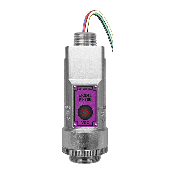
- Page 1 INSTRUCTION MANUAL Detcon Model PI-700 PI-700 VOC Gas Sensors This manual covers all ranges of PID based VOC Sensors DETCON, Inc. 4055 Technology Forest Blvd The Woodlands, Texas 77381 Ph.281.367.4100 / Fax 281.298.2868 www.detcon.com June 05, 2018 • Document #3228 • Revision 3.2...
- Page 2 Model PI-700 This page left intentionally blank Model PI-700...
-
Page 3: Table Of Contents
PID Plug-In Sensor Maintenance ...................... 31 Replacement of Intelligent Plug-in Sensor ..................38 Replacement of ITM ......................... 39 Replacement of PI-700 Sensor Assembly ..................39 Troubleshooting Guide ..........................41 Customer Support and Service Policy ......................44 PI-700 Sensor Warranty ..........................45 Appendix .............................. - Page 4 Figure 4 Sensor Assembly Breakaway ........................ 3 Figure 5 Intelligent Plug-in Sensor........................3 Figure 6 PI-700 ATEX Approval Label ....................... 4 Figure 7 Outline and Mounting Dimensions (Sensor Assembly only)..............7 Figure 8 Outline and Mounting Dimensions (Stainless Steel Junction Box) ............7 Figure 9 Outline and Mounting Dimensions (Aluminum Junction Box) .............
-
Page 5: Introduction
The PI-700 Intelligent Transmitter Module (ITM) is a fully encapsulated microprocessor-based package that is universal in design and will accept any Detcon intelligent plug-in PID gas sensor. The ITM design uses an internal intrinsically safe barrier circuit that lifts the requirement for use of flame arrestors to achieve Class 1, Division 1 (Zone1) area classification. -
Page 6: Modular Mechanical Design
Locking Set-Screw Figure 3 Sensor Assembly Front View 1.3 Modular Mechanical Design The Model PI-700 Sensor Assembly is completely modular and is made up of four parts (See Figure 4 for Assembly Break-away): 1) PI-700 Intelligent Transmitter Module (ITM) 2) Intelligent Plug-in Sensor (varies by range) 3) PI-700 Splash Guard Adapter with Integral Filter 4) Splash Guard. -
Page 7: Intelligent Plug-In Pid Gas Sensor
1.4 Intelligent Plug-in PID Gas Sensor The Detcon range of PID gas sensors are field proven, intelligent plug-in sensors (one type is used for ranges of 20ppm and less, another is used for ranges greater than 20ppm.) The Sensors employ 100% encapsulated circuitry and over-sized gold-plated connections that eliminate corrosion problems. -
Page 8: Installation
1. Install sensor only in areas with classifications matching with those described on the approval label. Follow all warnings listed on the label. Figure 6 PI-700 ATEX Approval Label 2. Ensure that the sensor is properly threaded into a suitable flameproof rated junction box with a downward pointing female ¾”... -
Page 9: Sensor Placement
Mount in an area void of high wind, accumulating dust, rain or splashing from hose spray, direct steam releases, and continuous vibration. If the sensor cannot be mounted away from these conditions then make sure the Detcon Harsh Environment Splashguard accessory is used. PI-700 Instruction Manual Rev. -
Page 10: Sensor Contaminants And Interference
2.4 Mounting Installation The PI-700 sensor assembly is designed to be threaded into a ¾” Female NPT fitting of a standard cast metal, Explosion-Proof Enclosure or Junction Box. Thread the sensor up until tight (5 turns is typically expected) and until the display is pointed in the direction that sensor will normally be viewed and accessed. -
Page 11: Figure 7 Outline And Mounting Dimensions (Sensor Assembly Only)
4" 3/4" NPT Ø0.265" Mounting Holes 8-32 Thread Ground Point Explosion Proof Enclosure Junction-Box (Detcon's SS Junction-Box shown) 12.5" Use Spacers to move the J-Box Typ. and Sensor Assembly away from the wall at least 0.25-0.5" detcon inc. MODEL to allow access to Sensor. -
Page 12: Figure 9 Outline And Mounting Dimensions (Aluminum Junction Box)
3.5" 8-32 Thread Ground Point Ø0.4" x .475" Mounting Holes Explosion Proof Enclosure Junction-Box 11" (Detcon's Mini SS Junction-Box shown) Typ. detcon inc. MODEL PI-700 Sensor Assembly Splash Guard 2.125" Figure 10 Outline and Mounting Dimensions (Mini Stainless Steel Junction Box) PI-700 Instruction Manual Rev. -
Page 13: Electrical Installation
18” of the enclosure. Crouse Hinds type EYS2, EYD2 or equivalent are suitable for this purpose. NOTE: The Detcon Warranty does not cover water damage resulting from water leaking into the enclosure through the conduit connections. -
Page 14: Field Wiring
Sensor Assembly Figure 11 Typical Installation NOTE: Any unused ports should be blocked with suitable ¾” male NPT plugs. Detcon supplies one ¾” NPT male plug with their accessory J-box enclosures. If connections are other than ¾” NPT, use an appropriate male plug of like construction material. -
Page 15: Figure 12 Sensor Wire Connections
NOTE: If the 4-20mA output is not being used, a 100-250Ω resistor must be installed between the mA and (-) terminals on the Transient Protection Module to ensure proper sensor operation. PI-700 Instruction Manual Rev. 3.2 Page 11 of 58... -
Page 16: Initial Start Up
11.5-30VDC (24VDC typical) and observe the following normal conditions: a) PI-700 display reads close to “0”, and no fault messages are flashing. b) A temporary upscale or downscale reading may occur as the sensor stabilizes. This upscale reading will typically decrease to near “0”ppm within 1-2 minutes of power-up, assuming there is no gas in the area of... - Page 17 Remove test gas and observe that the ITM display decreases to “0”. Initial operational tests are complete. PI-700 VOC gas sensors are factory calibrated prior to shipment, and should not require significant adjustment on start up. However, it is recommended that a complete calibration test and adjustment be performed 16 to 24 hours after power-up.
-
Page 18: Operation
While changing values inside menu items, if there is no magnet activity after 3-4 seconds the sensor will revert to the menu scroll. (Exception to this is with “Signal Output Check” mode.) PI-700 Instruction Manual Rev. 3.2 Page 14 of 58... -
Page 19: Operator Interface
Output Input Voltage Supply Sensor Temperature Gain Setting Raw Counts Set AutoSpan Level Set Serial ID Set Range Set Gas Factor Set Zero Offset Signal Output Check Restore Default Settings PI-700 Instruction Manual Rev. 3.2 Page 15 of 58... -
Page 20: Normal Operation
- Decrease X, XX, XXX - numeric values Raw Counts = XXX Figure 15 PI-700 Software Flowchart 3.3 Normal Operation In normal operation, the ITM Display continuously shows the current sensor reading, which will normally appear as “ 0 ”. Once every 60 seconds the LED display will flash the sensor’s measurement units and gas type (i.e. -
Page 21: Calibration Mode
Material Requirements: • Detcon PN 327-000000-000 MicroSafe™ Programming Magnet • Detcon PN 613-120000-700 700 Series Splash Guard with integral Cal Port and Calibration Wind Guard (P/N 943-000000-000) -OR- • Detcon PN 943-000006-132 Threaded Calibration Adapter •... - Page 22 NOTE 4: It is strongly recommended to use the target VOC gas to calibrate for span. This eliminates any possibility that Isobutylene cross-calibration is not accurate. Cross-calibration by use of other gasses should be confirmed by Detcon or at a minimum executed relative to the information provided in Table 5.
- Page 23 “Fault Detected” message will be displayed alternately with the sensor’s current reading. The 4-20mA output will be taken to 0mA and the ‘Range Fault’ fault bit will be set on the Modbus™ output. PI-700 Instruction Manual Rev. 3.2 Page 19 of 58...
-
Page 24: Program Mode
3-4 seconds (until the display starts to scroll “Status Is”). The display will scroll the complete list of sensor status parameters sequentially: PI-700 Instruction Manual Rev. 3.2 Page 20 of 58... - Page 25 Model PI-700 Sensor Model Type The menu item appears as: “Model PI-700” Current Software Version The menu item appears as: “Version 1.XX” Gas Type The menu item appears as: “ Gas Type = VOC” Range of Detection. The menu item appears as: “Range XXX”...
-
Page 26: Set Autospan Level
When the AutoSpan value is between 26 and 100, the adjustment increment is 5 When the AutoSpan value is between 101 and 1000, the adjustment increment is 50 When the AutoSpan value is between 1001 and 10000, the adjustment increment is 500 PI-700 Instruction Manual Rev. 3.2 Page 22 of 58... -
Page 27: Set Serial Id
3.5.4 Set Range The full-scale range of a PI-700 sensor is determined at the time of order. The Intelligent Plug-in Sensor is factory calibrated for this range. However, if the application requirements change and the user needs to alter the original range, the “Set Range”... -
Page 28: Set Gas Factor
900, 1000, 2000, 3000, 4000, 5000 – Normal ranges for High Range Sensors. The PI-700 ITM output range can be changed from the plug-in intelligent PID sensor range, but only within the following limitations: The range can be lowered by a factor of 4, or increased by a factor of 4. It is possible, but not advisable, to take a sensor outside the normal ranges for the sensor. -
Page 29: Signal Output Check
Move to another menu item by executing a momentary hold, or, return to Normal Operation via automatic timeout of about 15 seconds (the display will scroll “Restore Defaults” 4 times and then return to Normal Operation). PI-700 Instruction Manual Rev. 3.2 Page 25 of 58... -
Page 30: Program Features
3.6.2 Fault Diagnostic/Failsafe Features Fail-Safe/Fault Supervision Model PI-700 sensors are designed for Fail-Safe operation. If any of the diagnostic faults listed below are active, the ITM Display will scroll the message “Fault Detected” every 1 minute during normal operation. At any time during “Fault Detected”... - Page 31 Processor Fault will be set and will not clear until the fault condition has been cleared. If a Processor Fault occurs, the 4-20mA signal will be set at 0mA until the fault condition is resolved. PI-700 Instruction Manual Rev. 3.2...
- Page 32 If a Loop Fault occurs, the 4-20mA signal will be set at 0mA until the fault condition is resolved. If the 4-20mA current loop is still out of tolerance, contact Detcon at Service@detcon.com, or contact Detcon customer service.
-
Page 33: Rs-485 Modbus™ Protocol
Model DM-700 sensors feature Modbus™ compatible communications protocol and are addressable via the program mode. Other protocols are available. Contact the Detcon factory for specific protocol requirements. Communication is two wire, half duplex 485, 9600 baud, 8 data bits, 1 stop bit, no parity, with the sensor set up as a slave device. -
Page 34: Table 4 Modbus™ Special Registers
1,10,100, or 1000 (mA ) (Read only) Only possible ranges are 20, 50, 100, 200. Modbus register 40001 will contain either 20, 50, 100, or 200, range divisor is not necessary. PI-700 Instruction Manual Rev. 3.2 Page 30 of 58... -
Page 35: Service And Maintenance
The plug-in PID Sensor will need to be properly maintained to achieve proper long-term performance. All PID sensors use a UV lamp that has a finite lifetime. The Detcon PID UV lamp source is expected to last at least 1 year. -
Page 36: Figure 17 Splashguard Adapter With Integral Filter
For abnormally high rates of signal decay, clean the UV lamp monthly, using a Lamp Cleaning Kit, and replace the UV lamp every 9-12 months. For any proven cases where the zero baseline has drifted up, replace the detector cell. PI-700 Instruction Manual Rev. 3.2 Page 32 of 58... -
Page 37: Figure 19 Sensor Cell Parts
Figure 20 Removal of Filter Cap 3. With a fine tipped tweezers, remove both the Filter Media and set aside. PI-700 Instruction Manual Rev. 3.2 Page 33 of 58... -
Page 38: Figure 21 Removal Of Filter Media
6. With fine tipped tweezers, grasp the lamp by placing the tips in the housing notch and gently pulling it out. Be careful not to scratch the lamp lens or chip the edges. PI-700 Instruction Manual Rev. 3.2 Page 34 of 58... -
Page 39: Figure 24 Removal Of Lamp
Polishing Pad. Use a circular motion and try to keep the window surface flat relative to the pad. Five seconds of rubbing should be enough in most cases. Another indication of cleaning completeness is that about 1/16 the pad surface is used during the process. Figure 26 Polishing the Lamp PI-700 Instruction Manual Rev. 3.2 Page 35 of 58... -
Page 40: Figure 27 Lamp Installation
3. Using fine tipped tweezers, install the cell assembly. Align the pins with the corresponding sockets on the sensor and push down on the end with the pins. Make sure the cell assembly is flush with the lamp window. Figure 29 Cell Assembly installation PI-700 Instruction Manual Rev. 3.2 Page 36 of 58... -
Page 41: Figure 30 Spacer Installation
Filter Cap snaps on to the housing. If the Cap Key is incorrectly aligned there will be a noticeable bulge on the side of the cap. Figure 32 Replacing the Cap PI-700 Instruction Manual Rev. 3.2 Page 37 of 58... -
Page 42: Replacement Of Intelligent Plug-In Sensor
J-Box from condensing and accumulating moisture due to day-night humidity changes. This packet provides a critical function and should be replaced annually. Detcon’s PN is 960-202200-000. Lens and LCD Splashguard... -
Page 43: Replacement Of Itm
Perform Set AutoSpan Level, Set Serial ID, Set Range, and then perform a successful AutoZero and AutoSpan before placing sensor into service. 5.4 Replacement of PI-700 Sensor Assembly Caution: Hazardous areas must be declassified before removing the junction box cover... - Page 44 Remove splashguard. Unthread and remove the Splash Guard Adapter from the ITM. Feed the new PI-700 sensor assembly wires through the ¾” female NPT mounting hole and thread the assembly into the J-box until tight and the ITM lens faces toward the front access point. Connect the sensor assembly wires inside J-Box (Refer to Section 2.6, and Figure 12).
-
Page 45: Troubleshooting Guide
• Check for obstructions affecting cal gas hitting sensor face (including being wet, blocked, or corroded). • Verify adequate Sensor Life. • Clean or replace the PID lamp. PI-700 Instruction Manual Rev. 3.2 Page 41 of 58... - Page 46 • Verify Power source is stable. • Verify field wiring is properly shielded and grounded. • Contact Detcon to optimize shielding and grounding. Nuisance Alarms • Check condulet for accumulated water and abnormal corrosion on terminal blocks. PI-700 Instruction Manual Rev.
- Page 47 • Swap with new ITM to determine if the ITM’s 4-20mA output circuit has failed. • If the 4-20mA current loop is still out of tolerance, contact Detcon at Service@detcon.com, or contact Detcon customer service. No Communication – RS-485 Modbus™...
-
Page 48: Customer Support And Service Policy
Including all implied warranties of merchantability and fitness and the express warranties stated herein are in lieu of all obligations or liabilities on the part of Detcon Inc. for damages including, but not limited to, consequential damages arising out of, or in connection with, the performance of the product. -
Page 49: Pi-700 Sensor Warranty
ITM Electronics Warranty Detcon Inc. warrants, under intended normal use, each new Model 700 ITM to be free from defects in material and workmanship for a period of two years from the date of shipment to the original purchaser. All warranties and service policies are FOB the Detcon facility located in The Woodlands, Texas. -
Page 50: Appendix
Sensor Life: 2 years typical Measuring Ranges: Gas Dependent, ranges as low as 0-10ppm or as high as 0-5,000ppm (Consult Detcon) Special Low Range 0-500ppb Accuracy/ Repeatability: ±10% of reading of full-range or ±2% of range (greater of) Response Time: T50 <30 seconds;... - Page 51 Maximum distance is 13,300 feet with 14 AWG Serial Output: 2-wire twisted-pair shielded cable specified for RS-485 use Maximum distance is 4,000 feet to last sensor I/O Protection: Over-Voltage, Miss-wiring, EMI/RFI Immunity PI-700 Instruction Manual Rev. 3.2 Page 47 of 58...
-
Page 52: Gas Reference Table
IP = is the gases ionization potential (only gases < 10.6eV will respond to sensor) TWA/Time Weighted Average = generally accepted limit for safe 8 hour exposure (in ppm) ne = None Established PI-700 Instruction Manual Rev. 3.2 Page 48 of 58... - Page 53 C2H2Cl2 0.45 9.65 Dichloroethylene Dichloro-1-fluoroethane, 1,1- R-141B C2H3Cl2F Dichloromethane (see Methylene chloride) AK-255, mix of ~45% 3,3- dichloro-1,1,1,2,2-pentafluoro- propane (HCFC-225ca) & ~55% Dichloropentafluoropropane C3HCl2F5 1,3-Dichloro-1,1,2,2,3- pentafluoropropane (HCFC-225cb) Dichloropropane, 1,2 C3H6Cl2 10.87 PI-700 Instruction Manual Rev. 3.2 Page 49 of 58...
- Page 54 Ethyl lactate, Ethyl (S)-(-)- C5H10O3 DS-108F hydroxypropionate Ethyl mercaptan Ethanethiol C2H6S 0.56 9.29 Ethyl sulfide Diethyl sulfide C4H10S 8.43 Formaldehyde Formalin CH2O 10.87 C0.3 Formic acid CH2O2 11.33 Furfural 2-Furaldehyde C5H4O2 0.92 9.21 PI-700 Instruction Manual Rev. 3.2 Page 50 of 58...
- Page 55 Jet B, Turbo B, Wide cut type Jet fuel JP-4 m.w. 115 aviation fuel Jet fuel JP-5 Jet 5, Kerosene type aviaton fuel m.w. 167 Jet A-1, Kerosene type aviation Jet fuel JP-8 m.w. 165 fuel PI-700 Instruction Manual Rev. 3.2 Page 51 of 58...
- Page 56 142 207°C Mustard HD, Bis (2-chloroethyl) sulfide C4H8Cl2S 0.0005 Naphthalene Mothballs C10H8 0.42 8.13 Nitric oxide 9.26 Nitrobenzene C6H5NO2 9.81 Nitroethane C2H5NO2 10.88 Nitrogen dioxide 16.0 9.75 Nitromethane CH3NO2 11.02 PI-700 Instruction Manual Rev. 3.2 Page 52 of 58...
- Page 57 ~11.1 Tetrachloroethane, 1,1,2,2- C2H2Cl4 ~11.1 Tetraethyllead C8H20Pb ~11.1 0.008 Tetraethyl orthosilicate Ethyl silicate, TEOS C8H20O4Si ~9.8 Tetrafluoroethane, 1,1,1,2- HFC-134A C2H2F4 TFE, Tetrafluoroethylene, Tetrafluoroethene C2F4 10.12 Perfluoroethylene Tetrafluoromethane CFC-14, Carbon tetrafluoride >15.3 PI-700 Instruction Manual Rev. 3.2 Page 53 of 58...
- Page 58 IP = is the gases ionization potential (only gases < 10.6eV will respond to sensor) TWA/Time Weighted Average = generally accepted limit for safe 8 hour exposure (in ppm) ne = None established PI-700 Instruction Manual Rev. 3.2 Page 54 of 58...
-
Page 59: Spare Parts, Sensor Accessories, Calibration Equipment
9.3 Spare Parts, Sensor Accessories, Calibration Equipment Part Number Spare Parts S927-xx0000-xxxx PI-700 Intelligent Transmitter Module (ITM for VOC Gas Sensors) S967-xx0xxx-xxxx PI-700 ITM with Lower Housing, Cell, and Splash Guard 602-003295-FLT Model PI-700 Splash Guard Adapter with Integral Filter Replacement Plug-in VOC gas sensor (≤20ppm where XX=range) -
Page 60: Revision History
07/14/2008 PID Sensor maintenance procedure modified. 10/01/2009 Added in-line humidifying tube to calibration procedures and Spare parts, Added PI-700 Splashguard adapter to Spare parts. Updated engineering drawings to rev 4. 11/16/2009 Addition of Splashguard Adapter with Integral Filter to Maintenance and Accessories. -
Page 61: Model Pi
Model PI-700 EU DECLARATION OF CONFORMITY The Company Detcon Inc., 4055 Technology Forest Blvd, The Woodlands, TX, USA, declares that DM-700 PI-700 complies with the requirements of the following European Directives: I) European Directive ATEX 2014/34/UE dated from 26/02/14: Explosive... - Page 62 This page left intentionally blank Shipping Address: 4055 Technology Forest Blvd., The Woodlands Texas 77381 Mailing Address: P.O. Box 8067, The Woodlands Texas 77387-8067 www.detcon.com Phone: 888.367.4286, 281.367.4100 • Fax: 281.292.2860 • • sales@detcon.com PI-700 Instruction Manual Rev. 3.2 Page 58 of 58...
Need help?
Do you have a question about the PI-700 and is the answer not in the manual?
Questions and answers