Table of Contents
Advertisement
Quick Links
Advertisement
Table of Contents

Related Manuals for Detcon MicroSafe DM-534C


Summary of Contents for Detcon MicroSafe DM-534C
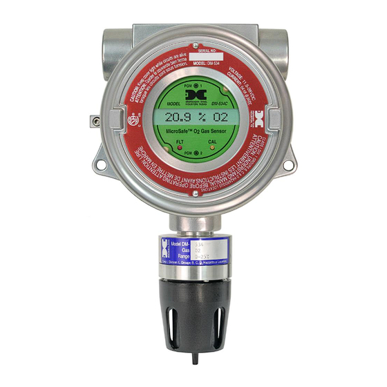
- Page 1 Detcon MicroSafe™ Model DM-534C Oxygen Deficiency Sensor (0-25% O2) Operator’s Installation and Instruction Manual DETCON, Inc. 4055 Technology Forest Blvd, Suite 100, The Woodlands, Texas 77381 Ph.281.367.4100 / Fax 281.298.2868 www.detcon.com July 20, 2018 • Document #2405 • Revision 1.5...
- Page 2 DM-534C Oxygen Sensor Assembly This page left intentionally blank DM-534C O2 Sensor Instruction Manual...
-
Page 3: Table Of Contents
DM-534C Oxygen Sensor Assembly Table of Contents DESCRIPTION ............................1 Sensor Technology ..........................1 Base Connector Board .......................... 2 Explosion Proof Enclosure ........................2 PRINCIPLE OF OPERATION ......................3 APPLICATION ............................3 Sensor Placement/Mounting ......................... 3 Interference Data ..........................4 SPECIFICATIONS .......................... - Page 4 Table 1 Interference Data ..........................4 Table 2 Field wiring Table ..........................6 Shipping Address: 4055 technology Forest Blvd, Suite 100., The Woodlands Texas 77381 Mailing Address: P.O. Box 8067, The Woodlands Texas 77387-8067 www.detcon.com Phone: 888.367.4286, 281.367.4100 • Fax: 281.292.2860 • • sales@detcon.com...
-
Page 5: Description
DM-534C Oxygen Sensor Assembly DESCRIPTION Detcon MicroSafe™ Model DM534C, oxygen deficiency sensors are non-intrusive “Smart” sensors designed to detect and monitor O2 in air over the range of 0-25%. One of the primary features of the sensor is its method of automatic calibration which guides the user through each step via instructions displayed on the backlit LCD. -
Page 6: Base Connector Board
DM-534C Oxygen Sensor Assembly Base Connector Board The base connector board is mounted in the explosion proof enclosure and includes: the mating connector for the control circuit, reverse input and secondary transient suppression, input filter, and lugless terminals for field wiring. Wiring to O2 Sensor Customer... -
Page 7: Principle Of Operation
DM-534C Oxygen Sensor Assembly Figure 4 Explosion proof enclosures PRINCIPLE OF OPERATION Method of detection is by a controlled rate of diffusion. Air and gas diffuse through a sintered stainless steel filter and a diffusion barrier. As oxygen is adsorbed into the electrolyte solution a current is generated between the cathode and anode electrodes. -
Page 8: Interference Data
DM-534C Oxygen Sensor Assembly Interference Data Table 1 Interference Data Methane 100% = 0 Hydrocarbons 100% = 0 Hydrogen 100% = < 2% Carbon Monoxide 20% = < 0.5% SPECIFICATIONS Method of Detection Air battery diffusion/adsorption Electrical Classification Class I; Groups B, C, D; Div. 1. Response Time (T90) T90 <... -
Page 9: Normal Operation
Field Wiring Table (4-20 mA output) Detcon MicroSafe™ O2 sensor assemblies require three conductor connection between power supplies and host electronic controllers. Wiring designators are + (DC), - (DC), and mA (sensor signal). Maximum single conductor resistance between sensor and controller is 10 ohms. Maximum wire size for termination in the sensor assembly terminal board is 14 AWG. -
Page 10: Sensor Location
DM-534C Oxygen Sensor Assembly Table 2 Field wiring Table Meters Feet 1200 2000 3000 Note 1: This wiring table is based on stranded tinned copper wire and is designed to serve as a reference only. Note 2: Shielded cable may be required in installations where cable trays or conduit runs include high voltage lines or other sources of induced interference. -
Page 11: Local Electrical Codes
DM-534C Oxygen Sensor Assembly Conduit "T" EYS Seal Fitting MODEL DM-534C HOUSTON, TEXAS MicroSafe O2 Gas Sensor Drain ALM ALM Figure 6 Typical Installation Local Electrical Codes Sensor and transmitter assemblies should be installed in accordance with all local electrical codes. Use appropriate conduit seals. -
Page 12: Remote Mounting Applications
This is usually true in instances where the gas sensor head must be mounted in a location that is difficult to access. Such a location creates problems for maintenance and calibration activities. Detcon provides the DM-534C sensor in a remote-mount configuration in which the sensor (Model DM-534C-RS) and the transmitter (Model DM-534C-RT) are provided in their own condulet housing and are interfaced together with a three conductor cable. -
Page 13: Start Up
-Detcon PN 943-000006-132 Threaded Calibration Adapter -Detcon PN 942-001123-000 Zero Air cal gas or use ambient air if no combustible gas is present. a) Attach the calibration adapter to the threaded sensor housing. Apply the test gas at a controlled flow rate of 500 ml/m. -
Page 14: Calibration
-Detcon PN 613-120000-000 Splash Guard with integral Cal Port -OR- -Detcon PN 943-000006-132 Threaded Calibration Adapter -Detcon PN 942-001123-000 Zero Air cal gas or use ambient air if no combustible gas is present. Programming Magnet Operating Instructions Operator interface to MicroSafe™ gas detection products is via magnetic switches located behind the transmitter face plate. -
Page 15: Calibration Procedure - Span
DM-534C Oxygen Sensor Assembly Calibration Procedure - Span NOTE 1: Before performing an ambient air O span calibration, be sure there is no oxygen deficient condition present. CAUTION: Verification of the correct calibration gas level setting and calibration span gas concentration is required before “span” calibration. These two numbers must be equal. -
Page 16: Additional Notes
DM-534C Oxygen Sensor Assembly Additional Notes 1. Upon entering the calibration menu, the 4-20 mA signal drops to 2 mA and is held at this level until you return to normal operation. 2. If during calibration the sensor circuitry is unable to attain the proper adjustment for span, the sensor will enter into the calibration fault mode and cause the display to alternate between the sensor’s current status reading and the calibration fault screen which appears as: “CAL FAULT”... -
Page 17: Status Of Programming And Sensor Life
“CAL FAULT” Fail-safe/Fault Supervision Detcon MicroSafe™ sensors are programmed for failsafe operation. Any of the following fault condition will illuminate the fault LED, and cause the display to read its corresponding fault condition: “SENSOR FAULT”, or “CAL FAULT”. -
Page 18: Display Contrast Adjust
Display Contrast Adjust Detcon MicroSafe™ sensors feature a 16-character backlit liquid crystal display. Like most LCDs, character contrast can be affected by viewing angle and temperature. Temperature compensation circuitry included in the MicroSafe™... -
Page 19: 10.0 Spare Parts List
943-000006-132 Calibration Adapter for FP, IR, DM and O2 Sensors 500-005065-007 Connector board 327-000000-000 Programming Magnet 897-850902-010 Detcon Alum Condulet w/Window Cover 960-202200-000 Condensation prevention packet (replace annually). 370-399100-000 Plug in replacement O2 sensor cell 925-345400-025 Plug in control circuit... -
Page 20: 11.0 Warranty
Detcon, Inc., further provides for a five year fixed fee service policy covering the control circuit wherein any failed part shall be repaired for a fee of $55.00. The fixed fee service policy shall affect any necessary factory repair for the period following the two-year warranty period and shall end five years after expiration of the warranty. -
Page 21: Revision History
07/20/18 Updated Conduit Seal in Section 6.4 Shipping Address: 4055 technology Forest Blvd, Suite 100., The Woodlands Texas 77381 Mailing Address: P.O. Box 8067, The Woodlands Texas 77387-8067 www.detcon.com Phone: 888.367.4286, 281.367.4100 • Fax: 281.292.2860 • • sales@detcon.com DM-534C O2 Sensor Instruction Manual Rev.
Need help?
Do you have a question about the MicroSafe DM-534C and is the answer not in the manual?
Questions and answers