Table of Contents
Advertisement
Advertisement
Table of Contents

Related Manuals for Detcon FP-700


Summary of Contents for Detcon FP-700
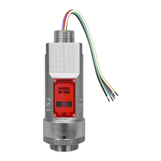
- Page 1 INSTRUCTION MANUAL Detcon Model FP-700 FP-700 Combustible Gas Sensor 0-100% LEL 0-50% LEL DETCON, Inc. 4055 Technology Forest Blvd The Woodlands, Texas 77381 Ph.281.367.4100 / Fax 281.298.2868 www.detcon.com June 05, 2018 • Document #3168 • Revision 5.1...
- Page 2 Model FP-700 This page left intentionally blank Model FP-700...
-
Page 3: Table Of Contents
Condensation Prevention Packet ....................... 32 Replacement of Plug-in Combustible Gas Sensor ................33 Replacement of ITM ......................... 33 Replacement of FP-700 Sensor Assembly ..................34 Troubleshooting Guide ..........................35 Customer Support and Service Policy ......................38 FP-700 Sensor Warranty ..........................39 Appendix .............................. - Page 4 Figure 14 Sensor Wire Connections ........................13 Figure 15 Magnetic Programming Tool ......................15 Figure 16 Magnetic Programming Switches ...................... 15 Figure 17 FP-700 Software Flowchart ....................... 17 Figure 18 Sensor Assembly ..........................32 Figure 19 Plug-in Sensor (Bottom View) ......................35 List of Tables Table 1 Wire Gauge vs.
-
Page 5: Introduction
The technique is referred to as non-selective and may be used to monitor most any combustible gas. Detcon catalytic bead sensors are specifically designed to be resistant to poisons such as sulfides, chlorides, and silicones. -
Page 6: Sensor Electronics Design
ITM. Calibration can be accomplished without declassifying the area. Electrical classifications are Class I, Division 1, Groups B C D, Class I, Zone 1, Group IIB+H and II 2G Ex d IIB+H FP-700 Instruction Manual Rev. 5.1 Page 2 of 46... -
Page 7: Modular Mechanical Design
Lockdown Set-Screw Figure 5 Sensor Assembly Front View 1.3 Modular Mechanical Design The Model FP-700 Sensor Assembly is completely modular and made up of four parts (See Figure 6 for Assembly Break-away): 1) FP-700 Intelligent Transmitter Module (ITM) 2) Field Replaceable Plug-in Combustible Gas Sensor... -
Page 8: Plug-In Replaceable Sensor
The Detcon combustible gas sensor has an infinite shelf life, and is supported by a 2-year warranty. The expected service life is 3-5 years. -
Page 9: Installation
Flammable Gases. Performance Testing was completed by CSA Group on March 28, 2018. This Model FP-700 detector is performance tested only for methane gas measurement in the 0-100 % LEL (0-5% by volume) range and with use of Accessory PN 613-120000-700 Sensor Splashguard with integral Cal Port. -
Page 10: Sensor Placement
The undetected migration of gas clouds should not be allowed to approach concentrated personnel areas such as control rooms, maintenance or warehouse buildings. A more general and applicable thought toward selecting sensor location is combining leak source and perimeter protection in the best possible configuration. FP-700 Instruction Manual Rev. 5.1 Page 6 of 46... -
Page 11: Sensor Contaminants And Interference
2.3 Sensor Contaminants and Interference Detcon combustible gas sensors may be adversely affected by exposure to certain airborne substances. Loss of sensitivity or corrosion may be gradual if such materials are present in sufficient concentrations. The performance of the detector elements may be temporarily impaired during operation in the presence of substances described as inhibitors. -
Page 12: Mounting Installation
2.4 Mounting Installation The FP-700 sensor assembly is designed to be threaded into a ¾” Female NPT fitting of a standard cast metal, Explosion-Proof Enclosure or Junction Box. Thread the sensor up until tight (5 turns is typically expected) and until the display is pointed in the direction that sensor will normally be viewed and accessed. -
Page 13: Figure 10 Outline And Mounting Dimensions (Stainless Steel Junction Box)
4" 3/4" NPT Ø0.265" Mounting Holes 8-32 Thread Ground Point Explosion Proof Enclosure Junction-Box (Detcon's SS Junction-Box shown) 12.5" Use Spacers to move the J-Box Typ. and Sensor Assembly away from the wall at least 0.25-0.5" detcon inc. MODEL to allow access to Sensor. -
Page 14: Electrical Installation
3.45" 3.5" 8-32 Thread Ground Point Ø0.4" x .475" Mounting Holes Explosion Proof Enclosure Junction-Box 11" (Detcon's Mini SS Junction-Box shown) Typ. detcon inc. MODEL FP-700 Sensor Assembly LEL Sensor Splash Guard 2.125" Figure 12 Outline and Mounting Dimensions (Mini Stainless Steel Junction Box) 2.5 Electrical Installation... -
Page 15: Field Wiring
Sensor Assembly Figure 13 Typical Installation NOTE: Any unused ports should be blocked with suitable ¾” male NPT plugs. Detcon supplies one ¾” NPT male plug with their accessory J-box enclosures. If connections are other than ¾” NPT, use an appropriate male plug of like construction material. -
Page 16: Table 1 Wire Gauge Vs. Distance
Section 2.7 Initial Start Up CAUTION: Do not apply power to the sensor assembly in a hazardous area unless the junction box cover is tight and all electrical seals have been installed FP-700 Instruction Manual Rev. 5.1 Page 12 of 46... -
Page 17: Initial Start Up
2.7 Initial Start Up CAUTION: Do not apply power to the sensor assembly in a hazardous area unless the junction box cover is tight and all electrical seals have been installed FP-700 Instruction Manual Rev. 5.1 Page 13 of 46... - Page 18 Remove test gas and observe that the ITM display decreases to “0”. Initial operational tests are complete. Detcon FP-700 combustible gas sensors are factory calibrated prior to shipment, and should not require significant adjustment on start up. However, it is recommended that a complete calibration test and adjustment be performed 16 to 24 hours after power-up.
-
Page 19: Operation
While changing values inside menu items, if there is no magnet activity after 3-4 seconds the sensor will revert to the menu scroll. (Exception to this is with “Signal Output Check” mode.) FP-700 Instruction Manual Rev. 5.1 Page 15 of 46... -
Page 20: Operator Interface
Gas Factor Cal Factor 4-20mA Output Input Voltage Supply Operating Temperature Set AutoSpan Level Set Gas Factor Set Cal Factor Set Serial ID Set Bridge Voltage Signal Output Check Restore Default Settings FP-700 Instruction Manual Rev. 5.1 Page 16 of 46... -
Page 21: Normal Operation
- Decrease Temp = XX C X, XX, XXX - numeric values Figure 17 FP-700 Software Flowchart 3.3 Normal Operation In normal operation, the ITM Display continuously shows the current sensor reading, which will normally appear as “ 0 ”. Once every 60 seconds the LED display will flash the sensor’s measurement units and gas type (i.e. % LEL). -
Page 22: Calibration Mode (Autozero And Autospan)
Detcon PN 943-000006-132 Threaded Calibration Adapter • Detcon PN 942-001123-000 Zero Air cal gas or use ambient air if no combustible gas is present. NOTE 1: The zero gas source should have a normal background concentration of 20.9% O2. Pure Nitrogen gas standards should not be used or errors may result. - Page 23 Model FP-700 Material Requirements: • Detcon PN 327-000000-000 MicroSafe™ Programming Magnet • Detcon PN 613-120000-700 700 Series Splash Guard with integral Cal Port and Calibration Wind Guard (P/N 943-000000-000) -OR- • Detcon PN 943-000006-132 Threaded Calibration Adapter • Detcon PN 942-520124-050 50% LEL Methane in balance air (recommended for 0-100% LEL range)
-
Page 24: Program Mode
Program Mode also provides for adjustment of the AutoSpan Level, Bridge Voltage, Gas Factor, Cal Factor, and Serial ID. Additionally, it includes the Restore Factory Defaults and Signal Output Check diagnostic functions. FP-700 Instruction Manual Rev. 5.1 Page 20 of 46... -
Page 25: Navigating Program Mode
Current Software Version The menu item appears as: “V X.XXZ” Range of Detection The menu item appears as: “Range XXX” Serial ID address. The menu item appears as: “Serial ID XX” FP-700 Instruction Manual Rev. 5.1 Page 21 of 46... -
Page 26: Set Autospan Level
Level”). The display will switch to “XX“ (where XX is the current gas level). Swipe the magnet momentarily over PGM2 to increase or PGM1 to decrease the AutoSpan Level until the correct level is displayed. When the FP-700 Instruction Manual Rev. 5.1... -
Page 27: Set Gas Factor
3.5.4 Set Gas Factor Because of the catalytic bead sensor’s almost universal response to combustible gases, the FP-700 sensor can be configured to specifically detect any of the combustible gases listed in Table 2. This gas is referred to as the “target gas”. -
Page 28: Set Cal Factor
3.5.5 Set Cal Factor Because of the catalytic bead sensor’s almost universal response to combustible gases, the FP-700 sensor can be span calibrated with any of the combustible gases listed in Table 2 above. This specific gas is referred to as the “cal gas”. -
Page 29: Set Serial Id
Operation). 3.5.6 Set Serial ID Detcon Model FP-700 sensors can be polled serially via RS-485 Modbus™ RTU. Refer to Section 4.0 for details on using the Modbus™ output feature. Set Serial ID is used to set the Modbus™ serial ID address. It is adjustable from 01 to 256 in hexadecimal format (01-FF hex). -
Page 30: Signal Output Check
NOTE: The “Set Bridge Voltage” function is executed during factory calibration of every FP- 700 sensor. In the field, this menu item is only needed when a replacement plug-in sensor is being installed, or when mating a new FP-700 ITM with an existing plug-in sensor. The menu item appears as: “Set Bridge Voltage”. -
Page 31: Program Features
AutoSpan: AutoSpan Settings are lost and user must perform new AutoSpan (Section 3.4). 3.6 Program Features Detcon FP-700 gas sensors incorporate a comprehensive set of diagnostic features to achieve Fail-Safe Operation. These Operational features and Failsafe Diagnostic features are detailed below. -
Page 32: Fault Diagnostic/Failsafe Features
3.6.2 Fault Diagnostic/Failsafe Features Fail-Safe/Fault Supervision Model FP-700 sensors are designed for Fail-Safe operation. If any of the diagnostic faults listed below are active, the ITM Display will alternately scroll the message “Fault Detected” during normal operation. At any time while the “Fault Detected” message is scrolling, hold the programming magnet over PGM2 for 1 second to display the active fault(s). - Page 33 If a Loop Fault occurs, the 4-20mA signal will be set at 0mA until the fault condition is resolved. If the 4-20mA current loop is still out of tolerance, contact Detcon at Service@detcon.com, or contact Detcon customer service.
-
Page 34: Rs-485 Modbus™ Protocol
Model DM-700 sensors feature Modbus™ compatible communications protocol and are addressable via the program mode. Other protocols are available. Contact the Detcon factory for specific protocol requirements. Communication is two wire, half duplex 485, 9600 baud, 8 data bits, 1 stop bit, no parity, with the sensor set up as a slave device. -
Page 35: Table 4 Modbus™ Special Registers
(Read only) 1,10,100, or 1000 (mA ) Only possible ranges are 20, 50, 100, 200. Modbus register 40001 will contain either 20, 50, 100, or 200, range divisor is not necessary. FP-700 Instruction Manual Rev. 5.1 Page 31 of 46... -
Page 36: Service And Maintenance
J-Box from condensing and accumulating moisture due to day-night humidity changes. This packet provides a critical function and should be replaced annually. Detcon’s PN is 960-202200-000. Bottom Housing Lens and LCD... -
Page 37: Replacement Of Plug-In Combustible Gas Sensor
Open the junction box and remove power to FP-700 sensor by lifting the + 24VDC wire in J-Box b) Use a M1.5 Allen wrench to release the locking setscrew that locks the ITM and bottom housing together (One turn will suffice –... -
Page 38: Replacement Of Fp-700 Sensor Assembly
Use a wrench and loosen the locking nut at the top of the ITM and unthread the ITM from the junction box. 04) Feed the new FP-700 sensor assembly wires through the ¾” female NPT mounting hole and thread the assembly into the J-box until tight and the ITM lens faces toward the front access point. -
Page 39: Troubleshooting Guide
Replace the plug-in sensor. Stability Fault Probable Causes: Failed Sensor, empty or close to empty Cal Gas Cylinder, or problems w/ cal gas and delivery. • Check Bridge Voltage (should be 2.7 +/- 0.2VDC). FP-700 Instruction Manual Rev. 5.1 Page 35 of 46... - Page 40 Evaluate area for presence of poisoning or inhibiting gases as listed in Section 2.3. • Increase calibration frequency. • Note the sensor’s serial # and report repetitive problems to Detcon’s Repair Department. • Replace plug-in sensor. Unstable Output/ Sudden spiking Possible Causes: Unstable power supply, inadequate grounding, or inadequate RFI protection.
- Page 41 • Swap with new ITM to determine if the ITM’s 4-20mA output circuit is faulty. • If the 4-20mA current loop is still out of tolerance, contact Detcon at Service@detcon.com, or contact Detcon customer service. No Communication – RS-485 Modbus™...
-
Page 42: Customer Support And Service Policy
Defective or damaged equipment must be shipped to the Detcon Inc. factory or representative from which the original shipment was made. In all cases this warranty is limited to the cost of the equipment supplied by Detcon Inc. The customer will assume all liability for the misuse of this equipment by its employees or other contracted personnel. -
Page 43: Fp-700 Sensor Warranty
ITM Electronics Warranty Detcon Inc. warrants, under intended normal use, each new Model 700 Intelligent Sensor Module to be free from defects in material and workmanship for a period of two years from the date of shipment to the original purchaser. -
Page 44: Appendix
*T50 < 10 seconds, T90 < 30 seconds *Test Results confirmed using CSA Response Time Flusher Test Apparatus. Results are for methane gas only. Specified response times represent FP-700 detector only and do not reflect use when combined with other Control Units. - Page 45 Normal operation = 68mA (<1.7 watt) Maximum = 85mA (2 watts) Inrush current: 1.0A @ 24V RFI/EMI Protection: Complies with EN50270:2006 Analog Output: Linear 4-20mA DC current (1000 ohms maximum loop load @ 24VDC) FP-700 Instruction Manual Rev. 5.1 Page 41 of 46...
- Page 46 Maximum distance is 13,300 feet with 14 AWG Serial Output: 2-wire twisted-pair shielded cable specified for RS-485 use Maximum distance is 4,000 feet to last sensor I/O Protection: Over-Voltage, Miss-wiring, EMI/RFI Immunity FP-700 Instruction Manual Rev. 5.1 Page 42 of 46...
-
Page 47: Spare Parts, Sensor Accessories, Calibration Equipment
9.2 Spare Parts, Sensor Accessories, Calibration Equipment Part Number Spare Parts S927-xx0000-xxxx FP-700 Intelligent Transmitter Module (ITM) S967-xx0xxx-xxxx FP-700 ITM with Cell, Lower Housing, and Splashguard Adapter 602-003152-000 Model 700 Housing Bottom Assembly (includes Flame Arrestor) 370-201600-700 Replacement Plug-in Sensor 500-003087-100... -
Page 48: Revision Log
Updated Field Wiring Section 02/28/14 Update 4-20mA wiring and Specifications 06/16/16 Update cert specs, update technical information. 04/17/18 Updates for ANSI/UL 12.13.01:2013 Performance Testing 06/05/18 Updated Conduit Seal in Section 2.5 FP-700 Instruction Manual Rev. 5.1 Page 44 of 46... -
Page 49: Model Fp
Model FP-700 EU DECLARATION OF CONFORMITY The Company 3M dba Detcon Inc., 4055 Technology Forest Blvd, The Woodlands, TX, USA, declares that Model 700A (DM, FP, IR, PI, TP) complies with the requirements of the following European Directives: I) European Directive ATEX 2014/34/UE dated from 26/02/14: Explosive Atmospheres... - Page 50 This page left intentionally blank Shipping Address: 4055 Technology Forest Blvd., The Woodlands Texas 77381 Mailing Address: P.O. Box 8067, The Woodlands Texas 77387-8067 www.detcon.com Phone: 888.367.4286, 281.367.4100 • Fax: 281.292.2860 • • sales@detcon.com FP-700 Instruction Manual Rev. 5.1 Page 46 of 46...
Need help?
Do you have a question about the FP-700 and is the answer not in the manual?
Questions and answers