Table of Contents
Advertisement
Quick Links
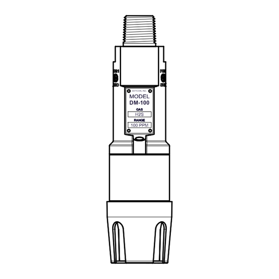
Model DM-100
DM-100 Toxic Gas Sensors
DM-100 O2 Deficiency Sensors
DETCON, INC.
DM-100
GAS
H2S
RANGE
100 PPM
Operator's Installation and Instruction Manual
Covers all Model DM-100 Sensors
DETCON, Inc.
4055 Technology Forest Blvd,
The Woodlands, Texas 77381
Ph.281.367.4100 / Fax 281.298.2868
www.detcon.com
June 08, 2018 • Document #3604 • Revision 3.5
Advertisement
Table of Contents

Related Manuals for Detcon DM-100 Series


Summary of Contents for Detcon DM-100 Series
- Page 1 Model DM-100 DM-100 Toxic Gas Sensors DM-100 O2 Deficiency Sensors DETCON, INC. DM-100 RANGE 100 PPM Operator’s Installation and Instruction Manual Covers all Model DM-100 Sensors DETCON, Inc. 4055 Technology Forest Blvd, The Woodlands, Texas 77381 Ph.281.367.4100 / Fax 281.298.2868 www.detcon.com...
- Page 2 Model DM-100 This page left intentionally blank Model DM-100...
-
Page 3: Table Of Contents
Modular Mechanical Design ....................... 2 Model 100 Standard Terminal Board (Optional) ................4 DM-100 Display Terminal Board (Optional) ..................4 DM-100 Series Display (Optional) ..................... 5 Wireless Transceiver and Battery Pack (Optional) ................5 Installation ..............................6 Hazardous Locations Installation Guidelines for Safe Use ..............6 Sensor Placement .......................... - Page 4 Table 4 Interfering Gases ........................... 31 Table 5 Cross Interference Table ........................32 Shipping Address: 4055 Technology Forest Blvd, The Woodlands, Texas 77381 Mailing Address: P.O. Box 8067, The Woodlands Texas 77387-8067 www.detcon.com Phone: 888.367.4286, 281.367.4100 • Fax: 281.292.2860 • • sales@detcon.com...
-
Page 5: Introduction
Splash Guard Cal Adapter. Optionally, the sensor can be installed on an explosion proof junction box with a Model 100 Terminal Board and may include a Model 100 Loop Powered LED display. Other options are available, contact Detcon for more information. Model 100 DETCON, INC. -
Page 6: Modular Mechanical Design
Model DM-100 The DM-100 O deficiency sensor technology is a two electrode galvanic metal air battery type cell, which is housed as a field replaceable intelligent plug-in sensor. The cell is diffusion limited and functions as a direct current generator proportional to the amount of oxygen adsorption. The sensors are temperature compensated and show good accuracy and stability over the operating temperature range of -20°... -
Page 7: Figure 5 Functional Block Diagram
The sensor can be accessed and replaced in the field easily by releasing the locking screw and unthreading the Splash Guard Adapter. Detconꞌs family of toxic sensors has a long shelf life and is supported by an industry-leading warranty (Section 7). -
Page 8: Model 100 Standard Terminal Board (Optional)
Model DM-100 1.3 Model 100 Standard Terminal Board (Optional) If the sensor is ordered with an explosion proof condulet/junction box, the sensor will come with the Model 100 Standard Terminal Board mounted in the J-Box (Figure 7). This terminal board affords the user easy plug- in connectors for use in wiring the unit during installation, and convenient test points for measuring the milliamp (mA) output. -
Page 9: Dm-100 Series Display (Optional)
1.5 DM-100 Series Display (Optional) The DM-100 Series Display is a 4-digit LED display that provides a direct display of the sensor readings. In units that are ordered with the optional display, the display is mounted directly onto the J3 Beau connector of the Display Terminal Board so the display can be easily seen through the J-box window. -
Page 10: Installation
Model DM-100 2. Installation 2.1 Hazardous Locations Installation Guidelines for Safe Use 1. Install the sensor only in areas with classifications matching the approval label. Follow all warnings listed on the label. Figure 10 Approval Label 2. For intrinsically safe Ex ia installations, follow the intrinsically safe installation guidelines shown in control drawing #3993, Section 8.5. -
Page 11: Sensor Placement
Model DM-100 13. The DM-100 may be used as an oxygen deficiency sensor; the DM-100 must not be used for detecting oxygen concentrations expected to be greater than 21%. 14. The DM-100 must only use gas sensor cell models 371-xxxxxx-xxx (Table 5, Section 8.1). No other gas sensor cells shall be used. -
Page 12: Sensor Contaminants And Interference
The DM-100 should be vertically oriented so that the sensor points straight downward. The explosion-proof enclosure or junction box is typically mounted on a wall or pole (Figure 11). Detcon provides a selection of standard junction boxes in both Aluminum and Stainless Steel. -
Page 13: Electrical Installation
Model DM-100 When mounting on a pole, secure the Junction Box to a suitable mounting plate and attach the mounting plate to the pole using U-Bolts. (Pole-Mounting brackets for Detcon Junction Box’s are available separately.) 6.1" NPT Ports 5.5" 4.35"... -
Page 14: Field Wiring
18" of the enclosure. Crouse Hinds type EYS2, EYD2 or equivalent are suitable for this purpose. The Detcon Warranty does not cover water damage resulting from water leaking into the NOTE enclosure. -
Page 15: Dm-100 Display Terminal Board Settings
Model DM-100 Terminal Connections – with Junction Box Option Do not apply System power to the sensor until all wiring is properly terminated. Refer to Section 2.7, Initial Start Up. CAUTION 1. Remove the junction box cover. 2. If the sensor has the Display option installed, unplug the display from the terminal board by pulling the display out of the junction box. - Page 16 • Detcon PN 943-01747-T05 Teflon Calibration Adapter for highly reactive gases • Detcon Span Gas; 50% of range target gas in balance N2 or Air at fixed flow rate between 200-500cc/min (500cc/min is preferred) • DVM (if a loop powered display is not installed)
-
Page 17: O 2 Deficiency Sensors
After a warm-up period of 5 minutes the sensor should be checked to verify response to O deficiency. Material Requirements • Detcon PN 613-120000-700 700 Series Splash Guard with integral Cal Port and Calibration Wind Guard (P/N 943-000000-000) -OR- • Detcon PN 943-000006-132 Threaded Calibration Adapter - OR - •... -
Page 18: Operation
For momentary contact the programming magnet is briefly held over a switch location. The location of PGM1 and PGM2 are shown in Figure 14. Program 1 Program 2 DETCON, INC. DM-100 100 PPM Figure 14 Magnetic Programming Switches 3.1 Normal Operation... -
Page 19: Calibration
Detcon PN 943-000006-132 Threaded Calibration Adapter - OR - • Detcon PN 943-01747-T05 Teflon Calibration Adapter for highly reactive gases • Detcon PN 942-001123-000 Zero Air cal gas (or use ambient air if no target gas is present). • Detcon PN 942-640023-100 Nitrogen 99.99% •... - Page 20 Model DM-100 3.3.1.1 Display Not Installed 1. If a DM-100 Display is not installed on the sensor, set a DVM to measure millivolts, and connect it across TP1 and TP2 on the terminal board. The DVM will read the voltage drop across a 10Ω resistor. The resistor develops a 10mV voltage drop per 1mA of current.
-
Page 21: Span Calibration
Detcon PN 943-01747-T05 Teflon Calibration Adapter for highly reactive gases • Detcon Span Gas (See Detcon for Ordering Information). Recommended span gas is 50% of range with target gas. Other suitable span gas sources containing the target gas in air or N2 balance are acceptable. - Page 22 Model DM-100 3. From normal operation, hold the programming magnet over PGM2 for at least 3 seconds. Apply the span calibration test gas for toxic gas sensors at a flow rate of 200-500cc/min (500cc/min is the recommended flow rate). The DVM reading will remain at 2mA or "0" for 2 minutes. 4.
-
Page 23: Fault Diagnostic/Failsafe Feature
Model DM-100 3. Hold PGM2 for three seconds and Auto span routine is executed and APPLY XXXXX UUU GGG is scrolled across the display. Where XXXXX represent the auto span level, UUU represent the units (% or PPM), and GGG represent the gas type. Output current from the sensor will drop to 3.5mA. 4. -
Page 24: Service And Maintenance
Model DM-100 4. Service and Maintenance Calibration Frequency In most applications, monthly to quarterly span calibration intervals will assure reliable detection. However, industrial environments differ. Upon initial installation and commissioning, close frequency tests should be performed, weekly to monthly. Test results should be recorded and reviewed to determine a suitable calibration interval. -
Page 25: Replacement Of Itm
Model DM-100 4.2 Replacement of ITM 1. Remove the power source to the sensor assembly. Disconnect all sensor wire connections at the Junction Box Terminal Board taking note of the wire connections. It is necessary to remove power to the Junction box while changing the ITM in order to NOTE maintain area classification. - Page 26 Model DM-100 9. Reconnect the power connector to the terminal board. 10. Re-install the DM-100 Display, if one was installed. 11. Reinstall the junction box cover, and restore power to the sensor. 12. Check operation of sensor assembly (Section 2.7, Initial Start Up). DM-100 Instruction Manual Rev.
-
Page 27: Troubleshooting Guide
Model DM-100 5. Troubleshooting Guide If the ITM detects any functional errors the ITM will bring the mA output to 0mA and hold it there until the problem has been resolved. If the unit has a Display, the display will show an error code. Error codes are displayed as FLXX where XX is the actual error code. - Page 28 • Contact Detcon to optimize shielding and grounding. • Add Detcon’s RFI Protection Circuit Accessory (PN 975-343002-007) if problem is proven RFI induced. Nuisance Alarms • Check condulet for accumulated water and abnormal corrosion on terminal board. If nuisance alarms are happening at night, suspect condensation in condulet.
-
Page 29: Smart Display Error Codes
Model DM-100 • Swap DM-100 Display Terminal Board with known good board. • Swap DM-100 Display with known good display. 5.1 Smart Display Error Codes These error codes are determined by the smart display and must be rectified before normal operation of the unit will continue. -
Page 30: Customer Support And Service Policy
Including all implied warranties of merchantability and fitness and the express warranties stated herein are in lieu of all obligations or liabilities on the part of Detcon Inc. for damages including, but not limited to, consequential damages arising out of, or in connection with, the performance of the product. -
Page 31: Dm-100 Sensor Warranty
ITM Electronics Warranty Detcon Inc. warrants, under intended normal use, each new Model 100 ITM to be free from defects in material and workmanship for a period of two years from the date of shipment to the original purchaser. All warranties and service policies are FOB the Detcon facility located in The Woodlands, Texas. -
Page 32: Appendix
Model DM-100 8. Appendix 8.1 Specifications System Specifications Sensor Type: Continuous diffusion/adsorption type 3-Electrode Electrochemical Sensor (2-Electrode for O Plug-in Replaceable Type Sensor Life: 2 years typical Measuring Ranges: 0-1ppm up to 0-10,000ppm (Toxic Gases) 0-1% up to 0-25% volume (O Accuracy/ Repeatability: ±2% of full-range (other Toxic Gases) ±1% of full-range (O... -
Page 33: Sensor Specific Data
Model DM-100 Analog Output: Linear 4-20mA DC current 750 ohms maximum loop load @ 24VDC 1.2 mA All Fault Diagnostics (without display) Sensor in calibration (without display) 3.25mA All Fault Diagnostics (with display) 3.5mA Sensor in calibration (with display) 4-20 mA 0-100% full-scale 22 mA Over-range condition Cable Requirements:... - Page 34 Model DM-100 Response Temperatur Humidity GasName Part Number Time SpanDrift Warranty e Range °C Range% (seconds) <1%signal Chlorine Dioxide 371-282800-050 T90<120 -20 to+40 10 to 95 2 years (<=10ppm) loss/month <5%signal Diborane 371-192100-005 T90<60 -20 to+40 20 to 95 1.5 years loss/month Ethanol 371-12EO00-100...
-
Page 35: Interference Table
Model DM-100 8.3 Interference Table To match the interfering gas symbol with the gas name, reference Table 4, Interfering Gases. Then refer to Table 5, Cross Interference Table which extends for five pages with each sensor specific gas repeated in each section of the table, for a column listing of 40 gases. - Page 36 Model DM-100 Table 5 Cross Interference Table Alcohols Amines Buten-1 40=340 40=75 40=170 340=40 340=75 340=170 75=40 75=340 75=170 100=0.01 170=40 170=340 170=75 140=40 140=340 140=75 140=170 1=0.55 (>10ppm) 1=0.18 (=10ppm) 100=0.013 0.15=0.2 50=40 50=340 50=75 50=170 180=40 180=340 180=75 180=170 220=40 220=340...
- Page 37 Model DM-100 Table 5 Cross Interference Table (pg.2) 40=140 40=100 40=135 40=150 40=50 40=180 340=140 340=100 340=135 340=150 340=50 340=180 75=140 75=100 75=135 75=150 75=50 75=180 300=8 1=-1 10%=-15 5000=0 300=0 0.5=-0.04 0.2=0.15 5=yes n/d 300=0 170=140 170=100 170=135 170=150 170=50 170=180 140=100...
-
Page 38: Table 5 Cross Interference Table
Model DM-100 Table 5 Cross Interference Table (pg.3) C-H's C-H's (U) 40=220 40=275 40=330 340=220 340=275 340=330 75=220 75=275 75=330 100=0 200=4 5=-3 10=0 1=0.4 %range=0 3000=0 10=0.1 100=0 100=0 10=0 170=220 170=275 170=330 140=220 140=275 140=330 100=<100 100=<60 10=<2 100=0 100=0 10=0... - Page 39 Model DM-100 Table 5 Cross Interference Table (pg.4) COCL 40=415 40=275 340=415 340=275 75=415 75=275 15=30 35=6 5=-1 0.05=0.005 100%=0 0.1=0.11 15=-1.5 35=0 5=˜10 170=415 170=275 140=415 140=275 15=<0.3 35==7 5=0.5 15=-0.75 35=0 5=˜5 (>10ppm) 15=0.25 35=0 5=1.66 (=10ppm) 10=-0.015 yes n/d yes n/d 0.05=0.006...
- Page 40 Model DM-100 Table 5 Cross Interference Table (pg.5) H5CH 40=45 40=200 40=200 40=55 340=45 340=200 340=200 340=55 75=45 75=200 75=200 75=55 5=-0.5 1=0.56 5=-0.1 170=45 170=200 170=200 170=55 140=45 140=200 140=200 140=55 5=-0.05 (>10ppm) 5=-0.016 (=10ppm) 1=0.72 50=45 50=200 50=200 50=55 180=45 180=200...
-
Page 41: Proper Application And Maintenance Of Acrylonitrile Sensor
ACN span calibration must take place. The end-user should work with Detcon to assure that a suitable amount of replacement Plug-in sensors are available on hand to handle the ongoing exchange of sensors that may require periodic replacement. -
Page 42: Intrinsically Safe Installation Guidelines, Control Drawing #3993
Model DM-100 8.5 Intrinsically Safe Installation Guidelines, Control Drawing #3993 Figure 15 Control Drawing #3993 DM-100 Instruction Manual Rev. 3.5 Page 38 of 41... -
Page 43: Spare Parts, Sensor Accessories, Calibration Equipment
500-005158-100 Model 100 Display Terminal Board (used with display option) 500-005158-200 Model 100 Display Terminal Board (used with battery option) 345-001560-100 Model 100 Display Assembly 975-343002-007 Detcon’s RFI Protection Circuit Accessory DM-100 Instruction Manual Rev. 3.5 Page 39 of 41... -
Page 44: Revision Log
Model DM-100 8.7 Revision Log Revision Date Changes made Approval 09/01/2010 Initial Release 11/08/2010 Update to Cross Interference table to correct wrong value for C2H3CL against CO. Previous value was 1250=100, corrected value is 200=100 11/17/2010 Added updated table for Jumper descriptions and Jumper settings on DM-100 Terminal Board 11/30/2010 Corrections to Cross Interference Table, and some spelling... -
Page 45: Model Dm
Model DM-100 Shipping Address: 4055 Technology Forest Blvd, The Woodlands, Texas 77381 Mailing Address: P.O. Box 8067, The Woodlands Texas 77387-8067 www.detcon.com Phone: 888.367.4286, 281.367.4100 • Fax: 281.292.2860 • • sales@detcon.com DM-100 Instruction Manual Rev. 3.5 Page 41 of 41...
Need help?
Do you have a question about the DM-100 Series and is the answer not in the manual?
Questions and answers