Table of Contents
Advertisement
INSTRUCTION MANUAL
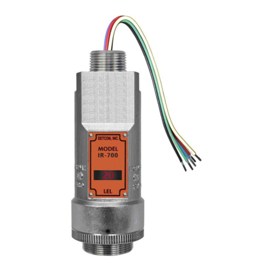
Detcon Model IR-700
IR-700 Combustible Gas Sensor
0-100% LEL and 0-50% LEL range
IR-700 CO
Carbon Dioxide Gas Sensor
2
All Ranges
DETCON, Inc.
.,
4055 Technology Forest Blvd
The Woodlands, Texas 77381
Ph.281.367.4100 / Fax 281.298.2868
www.detcon.com
June 05, 2018 • Document #3169 • Revision 4.3
Advertisement
Table of Contents

Related Manuals for Detcon IR-700


Summary of Contents for Detcon IR-700
- Page 1 INSTRUCTION MANUAL Detcon Model IR-700 IR-700 Combustible Gas Sensor 0-100% LEL and 0-50% LEL range IR-700 CO Carbon Dioxide Gas Sensor All Ranges DETCON, Inc. 4055 Technology Forest Blvd The Woodlands, Texas 77381 Ph.281.367.4100 / Fax 281.298.2868 www.detcon.com June 05, 2018 • Document #3169 • Revision 4.3...
- Page 2 Model IR-700 This page left intentionally blank Model IR-700...
-
Page 3: Table Of Contents
Condensation Prevention Packet ....................... 32 Replacement of IR Plug-in Combustible Gas Sensor ............... 32 Replacement of ITM ......................... 33 Replacement of IR-700 Sensor Assembly ..................34 Troubleshooting Guide ..........................35 Customer Support and Service Policy ......................38 IR-700 Sensor Warranty ..........................39 Appendix .............................. - Page 4 Figure 14 Sensor Wire Connections ........................12 Figure 15 Magnetic Programming Tool ......................15 Figure 16 Magnetic Programming Switches ...................... 15 Figure 17 IR-700 Software Flowchart ........................ 17 Figure 18 Sensor Assembly ..........................32 List of Tables Table 1 Wire Gauge vs. Distance ........................12 Table 2 Gas Factors ............................
-
Page 5: Introduction
CO . Unlike catalytic bead type sensors, Detcon IR sensors are completely resistant to poisoning from corrosive gases and they can operate in the absence of an oxygen background. The sensors are characteristically stable and capable of providing reliable performance for periods exceeding 5 years in most industrial environments. -
Page 6: Principle Of Operation
The IR sensor generates different signal sensitivity levels for different combustible hydrocarbon target gases. Unless otherwise specified the IR-700 sensor will be factory calibrated for methane service. If the target hydrocarbon gas is other than methane, then the unit will have to be span calibrated and configured accordingly per this Instruction Manual. -
Page 7: Sensor Electronics Design
Locking Set-Screw Figure 5 Sensor Assembly Front View 1.3 Modular Mechanical Design The Model IR-700 Sensor Assembly is completely modular and made up of four parts (See Figure 6 for Assembly Breakaway): 1) IR-700 Intelligent Transmitter Module (ITM) 2) Field Replaceable Plug-in Infra-Red Gas Sensor IR-700 Instruction Manual Rev. -
Page 8: Plug-In Replaceable Sensor
It can be accessed and replaced in the field very easily by releasing the locking screw and unthreading the housing bottom. The Detcon IR combustible hydrocarbon gas sensor and the CO gas sensor have an infinite shelf life, and are supported by a 5-year pro-rated warranty. -
Page 9: Installation
Detectors for Flammable Gases. Performance Testing was completed by CSA Group on March 28, 2018. This Model IR-700 detector is performance tested only for methane gas measurement in the 0-100 %LEL (0-5% by volume) range and with use of Accessory PN 613- 1200000-700 Sensor Splashguard with integral Cal Port. -
Page 10: Sensor Placement
Maintenance Access Consideration should be given to providing easy access for maintenance personnel. Consideration should also be given to the consequences of close proximity to contaminants that may foul the sensor prematurely. IR-700 Instruction Manual Rev. 4.3 Page 6 of 46... -
Page 11: Sensor Contaminants And Interference
2.4 Mounting Installation The IR-700 sensor assembly is designed to be threaded into a ¾” female NPT fitting of a standard cast metal Explosion-Proof Enclosure or Junction Box. Thread the sensor up until tight (5 turns is typically expected) and until the display is facing the direction that the sensor will normally be viewed and accessed. -
Page 12: Figure 9 Outline And Mounting Dimensions (Sensor Assembly Only)
Model IR-700 When mounting on a pole, secure the Junction Box to a suitable mounting plate and attach the mounting plate to the pole using U-Bolts. (Pole-Mounting brackets for Detcon J-Box accessories are available separately.) Sensor Wires Ferrite Cylinder Male 3/4" NPT Threads 5.48"... -
Page 13: Figure 10 Outline And Mounting Dimensions (Stainless Steel Junction Box)
4" 3/4" NPT Ø0.265" Mounting Holes 8-32 Thread Ground Point Explosion Proof Enclosure Junction-Box (Detcon's SS Junction-Box shown) 12.5" Use Spacers to move the J-Box Typ. and Sensor Assembly away from the wall at least 0.25-0.5" detcon inc. MODEL to allow access to Sensor. -
Page 14: Electrical Installation
3.5" 8-32 Thread Ground Point Ø0.4" x .475" Mounting Holes Explosion Proof Enclosure Junction-Box 11" (Detcon's Mini SS Junction-Box shown) Typ. detcon inc. MODEL IR-700 Sensor Assembly Splash Guard 2.125" Figure 12 Outline and Mounting Dimensions (Mini Stainless Steel Junction Box) 2.5 Electrical Installation... -
Page 15: Field Wiring
4-20mA output, and 2 conductor connections for the Modbus™ RS-485 serial interface. Wiring designations are + (DC), – (DC), mA (sensor signal), and Modbus™ RS-485 A (+), and B (-). Maximum wire size for termination in the Detcon J-Box accessory is 14AWG. IR-700 Instruction Manual Rev. -
Page 16: Figure 14 Sensor Wire Connections
4-20mA output is not used Wiring to Sensor Assembly Figure 14 Sensor Wire Connections a) Remove the junction box cover. Identify the terminal blocks for customer wire connections. IR-700 Instruction Manual Rev. 4.3 Page 12 of 46... -
Page 17: Initial Start Up
• Detcon PN 943-000006-132 Threaded Calibration Adapter • Detcon PN 942-520124-050 Span Gas; 50% LEL methane/balance Air at fixed flow rate of 200 cc/min (for 0-100% range) • Detcon PN 942-520124-025 Span Gas; 25% LEL methane/balance Air at fixed flow rate of 200 cc/min... - Page 18 Remove test gas and observe that the ITM display decreases to “0”. Initial operational tests are complete. Detcon IR-700 combustible gas sensors are factory calibrated prior to shipment, and should not require significant adjustment on start up. However, it is recommended that a complete calibration test and adjustment be performed 16 to 24 hours after power-up.
-
Page 19: Operation
”) are used on the LED display to indicate when the magnetic switches are activated. The location of “PGM1” and “PGM2” are shown in Figure 16. LED Display detcon inc. MODEL IR-700 Program Switch #1 Program Switch #2 Splash Guard Adapter Locking Set-Screw Figure 16 Magnetic Programming Switches IR-700 Instruction Manual Rev. 4.3 Page 15 of 46... -
Page 20: Operator Interface
Raw Reference Counts 4-20mA Output Input Voltage Supply Sensor Temperature Set AutoSpan Level Set Gas Type & Range Set Gas Factor Set Serial ID Set Sensor Gain Signal Output Check Restore Default Settings IR-700 Instruction Manual Rev. 4.3 Page 16 of 46... -
Page 21: Normal Operation
Temp = XX C dec - Decrease X, XX, XXX - numeric values Figure 17 IR-700 Software Flowchart 3.3 Normal Operation In normal operation, the ITM Display continuously shows the current sensor reading, which will normally appear as “0”. Once every 60 seconds the LED display will flash the sensor’s measurement units and gas type (i.e. % LEL). -
Page 22: Calibration Mode (Autozero And Autospan)
• Detcon PN 942-001123-000 Zero Air (or N2) cal gas, or use ambient air if no combustible gas is present. a) If the ambient air is known to contain no combustible hydrocarbon gas content, it can be used to calibrate zero. - Page 23 Model IR-700 Material Requirements: • Detcon PN 327-000000-000 MicroSafe™ Programming Magnet • Detcon PN 613-120000-700 700 Series Splash Guard with integral Cal Port and Calibration Wind Guard (P/N 943-000000-000) -OR- • Detcon PN 943-000006-132 Threaded Calibration Adapter • Detcon PN 942-520124-050 50% LEL Methane in balance air (recommended for 0-100% LEL range), •...
-
Page 24: Program Mode
ID. Additionally, it includes the Set Sensor Gain, Restore Factory Defaults, and Signal Output Check diagnostic functions. The Program Mode menu items appear in the order presented below: View Sensor Status Set AutoSpan Level Set Gas Type and Range Set Gas Factor IR-700 Instruction Manual Rev. 4.3 Page 20 of 46... -
Page 25: View Sensor Status
3-4 seconds (until the display starts to scroll “Status Is”). The display will scroll the complete list of sensor status parameters sequentially: Sensor Model Type The menu item appears as: “Model IR-700” Current Software Version The menu item appears as: “Version 1.XX”... -
Page 26: Set Autospan Level
PGM1 or PGM2 for 3-4 seconds to accept the new value. The display will scroll “Level Saved”, and revert to “Set AutoSpan Level” text scroll. IR-700 Instruction Manual Rev. 4.3 Page 22 of 46... -
Page 27: Set Gas Type& Range
3.5.4 Set Gas Factor Because of the IR sensor’s almost universal response to combustible hydrocarbon gases, the IR-700 sensor can be configured and calibrated to detect any of the combustible gases listed in the Table 2 and others not shown. -
Page 28: Set Serial Id
15 seconds (the display will scroll “Set Gas Factor” 4 times and then return to Normal Operation). 3.5.5 Set Serial ID Detcon Model IR-700 sensors can be polled serially via RS-485 Modbus™ RTU. Refer to Section 4.0 for details on using the Modbus output feature. IR-700 Instruction Manual Rev. -
Page 29: Set Sensor Gain
In the field, this menu item is only needed when a replacement plug-in IR sensor is being installed, or when mating a new IR-700 ITM with an existing plug-in sensor. It is also required if the Restore Defaults menu item is executed. -
Page 30: Restore Factory Defaults
15 seconds (the display will scroll “Restore Defaults” 4 times and then return to Normal Operation). Following the execution of “Restore Defaults”, the IR-700 will revert to its factory default settings. The default settings are: Serial ID = 01. The Serial ID must be set appropriately by the operator (Section 3.5.5). -
Page 31: Operational Features
3.6.2 Fault Diagnostic/Fail-Safe Features Fail-Safe/Fault Supervision Model IR-700 MicroSafe™ sensors are designed for Fail-Safe operation. If any of the diagnostic faults listed below are active, the ITM Display will scroll the message “Fault Detected” every 30 seconds during normal operation. At any time while the “Fault Detected” message is active, swipe the magnet over PGM1 or PGM2 to display the active fault(s). - Page 32 Memory Fault will be set and will not clear until the fault condition has been cleared. If a Memory Fault occurs, the 4-20mA signal will be set at 0mA until the fault condition is resolved. IR-700 Instruction Manual Rev. 4.3...
- Page 33 If a Loop Fault occurs, the 4-20mA signal will be set at 0mA until the fault condition is resolved. If the 4-20mA current loop is still out of tolerance, contact Detcon at Service@detcon.com, or contact Detcon customer service.
-
Page 34: Rs-485 Modbus™ Protocol
Model DM-700 sensors feature Modbus™ compatible communications protocol and are addressable via the program mode. Other protocols are available. Contact the Detcon factory for specific protocol requirements. Communication is two wire, half duplex 485, 9600 baud, 8 data bits, 1 stop bit, no parity, with the sensor set up as a slave device. -
Page 35: Table 4 Modbus™ Special Registers
(Read only) 1,10,100, or 1000 (mA ) Only possible ranges are 20, 50, 100, 200. Modbus register 40001 will contain either 20, 50, 100, or 200, range divisor is not necessary. IR-700 Instruction Manual Rev. 4.3 Page 31 of 46... -
Page 36: Service And Maintenance
A moisture condensation packet should be installed in every explosion proof Junction Box. The moisture condensation prevention packet will prevent the internal volume of the J-Box from condensing and accumulating moisture due to day-night humidity changes. This packet provides a critical function and should be replaced annually. Detcon’s PN is 960-202200-000. Plug-in Replacable Combustible... -
Page 37: Replacement Of Itm
Model IR-700 a) Remove power to IR-700 sensor by lifting the + 24 VDC wire in J-Box. b) Use a M1.5 Allen wrench to release the locking setscrew that locks the ITM and bottom housing together (One turn will suffice – Do not remove setscrew completely). -
Page 38: Replacement Of Ir-700 Sensor Assembly
Use a wrench and loosen the locking nut at the top of the ITM and unthread the ITM from the junction box. c) Feed the new IR-700 sensor assembly wires through the ¾” female NPT mounting hole and thread the assembly into the J-box until tight and the ITM lens faces toward the front access point. Connect the sensor assembly wires inside J-Box (Refer to Section 2.6, and Figure 14). -
Page 39: Troubleshooting Guide
Check validity of span gas and flow rate (check MFG date on cal cylinder). • Check for obstructions through stainless steel sinter element (including being wet). • Replace the plug-in IR sensor, and/or bottom housing. IR-700 Instruction Manual Rev. 4.3 Page 35 of 46... - Page 40 • If nuisance alarms are happening at night, suspect condensation in condulet. • Add or replace Detcon’s Condensation Prevention Packet P/N 960-202200-000. • Investigate presence of other combustible hydrocarbon gases that may be causing sensor response. Processor and/or Memory Faults •...
- Page 41 • Swap with new ITM to determine if the ITM’s 4-20mA output circuit has failed. • If the 4-20mA current loop is still out of tolerance, contact Detcon at Service@detcon.com, or contact Detcon customer service. No Communication – RS-485 Modbus™...
-
Page 42: Customer Support And Service Policy
Including all implied warranties of merchantability and fitness and the express warranties stated herein are in lieu of all obligations or liabilities on the part of Detcon Inc. for damages including, but not limited to, consequential damages arising out of, or in connection with, the performance of the product. -
Page 43: Ir-700 Sensor Warranty
ITM Electronics Warranty Detcon Inc. warrants, under intended normal use, each new Model 700 Intelligent Transmitter Module to be free from defects in material and workmanship for a period of two years from the date of shipment to the original purchaser. -
Page 44: Appendix
EN 50270:2006 Ingress Protection: NEMA 4X, IP66 NOTE: NEMA 4X, IP66 ratings have been achieved using PN 613-120000- 700 Sensor Splashguard with integral Cal Port. This IP rating does not imply IR-700 Instruction Manual Rev. 4.3 Page 40 of 46... - Page 45 Mounting holes (J-box) 3.5"; 89mm center to center Weight: 2 lbs; 0.907kg (sensor only) 6 lbs; 2.72kg (w/aluminum j-box) 9 lbs; 4.08kg (w/stainless steel j-box) 5 lbs; 2.27kg (w/mini stainless steel j-box) IR-700 Instruction Manual Rev. 4.3 Page 41 of 46...
- Page 46 Maximum distance is 13,300 feet with 14 AWG Serial Output: 2-wire twisted-pair shielded cable specified for RS-485 use Maximum distance is 4,000 feet to last sensor I/O Protection: Over-Voltage, Miss-wiring, EMI/RFI Immunity IR-700 Instruction Manual Rev. 4.3 Page 42 of 46...
-
Page 47: Spare Parts, Sensor Accessories, Calibration Equipment
9.2 Spare Parts, Sensor Accessories, Calibration Equipment Part Number Spare Parts S927-xx0000-xxxx IR-700 Intelligent Transmitter Module (ITM) S967-xx0xxx-xxxx IR-700 ITM with Lower Housing, Cell, and Splash Guard 602-004216-000 IR-700 Bottom Housing Assembly (includes Flame Arrestor) 370-3658CH-700 Replacement Plug-in IR Combustible Gas Sensor Sensor (Ranges ≤ 5%) -
Page 48: Revision Log
Changed ATEX certification line under Electrical Classification in B.M. Section 9.1 from “Eex d IIB+H T4” to “II 2 G Ex d IIB+H2 T4” to match ATEX approval label for IR-700. Added Revision Log Section 10. 04/25/11 Removed Teflon note in Section 2.5. - Page 49 Model IR-700 EU DECLARATION OF CONFORMITY The Company 3M dba Detcon Inc., 4055 Technology Forest Blvd, The Woodlands, TX, USA, declares that Model 700A (DM, FP, IR, PI, TP) complies with the requirements of the following European Directives: I) European Directive ATEX 2014/34/UE dated from 26/02/14: Explosive Atmospheres...
- Page 50 This page left intentionally blank Shipping Address: 4055 Technology Forest Blvd., The Woodlands Texas 77381 Mailing Address: P.O. Box 8067, The Woodlands Texas 77387-8067 www.detcon.com Phone: 888.367.4286, 281.367.4100 • Fax: 281.292.2860 • • sales@detcon.com IR-700 Instruction Manual Rev. 4.3 Page 46 of 46...
Need help?
Do you have a question about the IR-700 and is the answer not in the manual?
Questions and answers