
Related Manuals for LEYBOLD TRIVAC T Series


Summary of Contents for LEYBOLD TRIVAC T Series
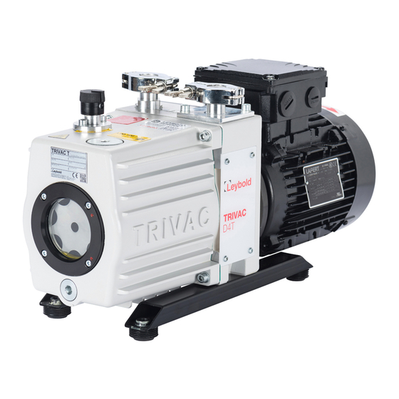
- Page 1 ® TRIVAC D4/8/16/30T Two-Stage Rotary Vane Pump Original Operating Instructions 300598802_002_C0 Part No: 312 31TE 312 36TE 312 41TE 312 46TE 312 51TE 312 56TE 312 61TE 312 66TE and other variants...
-
Page 2: Table Of Contents
Cleaning the Inlet Screen Disassembly and Reassembly of the Electric Motor 5.6.1 Checking the Coupling Maintaining the Gas Ballast Valve Troubleshooting Wearing Parts and Original Spare Parts Waste Disposal EC Declaration of Conformity 2 300598802_002_C0 - 10/2016 - © Leybold... - Page 3 Item No. in that order. We reserve the right to alter the design or any data given in these Operating Instructions. The illustrations are not binding. Retain the Operating Instructions for further use. 300598802_002_C0 - 10/2016 - © Leybold 3...
-
Page 4: Important Safety Information
Before starting up for the first time, the motor circuit must be equipped with a suitable protective motor switch. Please take note of the infor- mation in these Operating Instructions and on the electric motor (wiring diagram). 4 300598802_002_C0 - 10/2016 - © Leybold... -
Page 5: Thermal Hazards
T pumps including the accessories are fundamentally not suited for pumping of combustible and explosive gases or vapours. 0.6 Hazard caused by noise CAUTION The noise level produced by the pump is less than 60 dB(A). 300598802_002_C0 - 10/2016 - © Leybold 5... -
Page 6: Risk Of Damaging The Pump
Here, the ex- haust line must slope down and away from the pump. 13 In the case of custom pumps please note the information provided in the supplementary sheets. 6 300598802_002_C0 - 10/2016 - © Leybold... -
Page 7: Description
The gas ballast stops condensation of vapours in the pump chamber up to the limit of the water vapour tolerance as specified in the technical data for the pump. 300598802_002_C0 - 10/2016 - © Leybold 7... - Page 8 (1/3) operates independently of the operating mode of the pump, i.e. also with gas ballast. Bearings Non-return valve Pump chamber of TRIVAC Oil reservoir Oil pump Fig. 2 Schematic of the lubricating system 8 300598802_002_C0 - 10/2016 - © Leybold...
-
Page 9: Lubricants
T pumps are ready for operation with mineral oil. ® In case of operation of a TRIVAC T we instruct our vacuum pump oil LVO100. Use only the kind of oil specified by Leybold. NOTICE LVO100 oil Parts No. L100 01 L100 05... -
Page 10: Accessories
183 41 For D16/30T 1 Pipe bend, DN25KF 184 37 1 Centering ring with O-Ring, DN25KF 182 07 1 Clamping ring, DN25KF 183 42 Remarks: Any other request about accessories, please contact us. 10 300598802_002_C0 - 10/2016 - © Leybold... -
Page 11: Technical Data
Under such operating conditions the motor protection switch may respond. 3) The value is measured with 3 phase motor under 50Hz. 4) Cable with Schuko plug CEE 7/7 included in delivery. Cable with other type of plug are optional. 300598802_002_C0 - 10/2016 - © Leybold 11... - Page 12 ———— Ultimate total pressure without gas ballast - - - - - - - Ultimate total pressure with gas ballast (pos.1) ® Fig. 4 Pumping speed characteristics for the TRIVAC T pumps (50 Hz operation, SI units) 12 300598802_002_C0 - 10/2016 - © Leybold...
- Page 13 Description Pump 140.5 140.5 D16T D30T ® Fig. 5 Dimensional drawing for TRIVAC T pumps (dimensions a, b, c1, d, h and h1 are approximate) (dimensions in mm 1inch = 25.4 mm) 300598802_002_C0 - 10/2016 - © Leybold 13...
-
Page 14: Transport And Storing
When a pump is put into operation after it has been stored for over one year, standard maintenance should be run on the pump and the oil should also be exchanged (see Section 5.4). We recommend that you contact the Leybold Service. -
Page 15: Installation
The maximum gas inlet temperature must not exceed 60 °C. The maximum pressure at the inlet must not exceed atmospheric pres- sure (approximately 1013 mbar). Never apply overpressures to the pump’s inlet. The maximum exhaust pressure must not exceed 0.5 bar (overpressure). 300598802_002_C0 - 10/2016 - © Leybold 15... -
Page 16: Conforming Utilization
Intake port Exhaust port Gas ballast (GB) knob Gas ballast (GB) label (0 close GB / 1 open small GB / 2 open big GB) Oil-level glass Fig. 6 Connections and controls 16 300598802_002_C0 - 10/2016 - © Leybold... -
Page 17: Connection To The System
NOTICE Install the exhaust line with a downward slope (lower than the pump) so as to prevent condensate from flowing back into the pump. If this is not possible, insert a condensate trap. 300598802_002_C0 - 10/2016 - © Leybold 17... -
Page 18: Electrical Connections
In order to reduce the emission of oil vapours we recommend the installation of an additional exhaust filter (Leybold accessory, see Section 1.5). Depending on the type of applica- tion or the kind of pumped media, the corresponding regulations and infor- mation sheets must be observed. - Page 19 To reverse running invert L1 and L2. 220-240 V 50/60Hz 380-400 V 50Hz 380-480 V 50Hz Fig. 7 Motor connection diagram 300598802_002_C0 - 10/2016 - © Leybold 19...
-
Page 20: Operation
The noise will reduce to normal level after the pump runs nor- mally. 20 300598802_002_C0 - 10/2016 - © Leybold... -
Page 21: Operation
(if possible via a valve). Once all vapours have been pumped off from a process (e.g. during drying), the gas ballast valve can be closed to improve the attainable ultimate pres- sure. 300598802_002_C0 - 10/2016 - © Leybold 21... -
Page 22: Operating Temperature
Observe Safety Information 0.3. If - due to the ambient conditions - this temperature range is exceeded at ei- ther end of the range, contact Leybold Sales. The motor may accelerate with a delay when simultaneously an under voltage is present at the motor and the pump is at the minimum permissible and ambi- ent temperature. -
Page 23: Maintenance
All work must be carried out by suitably trained personnel. Maintenance or repairs carried out incorrectly will affect the life and per- formance of the pump and will void any warranty claims. Leybold offers practical courses on the maintenance, repair, and testing of ® TRIVAC T pumps. -
Page 24: Maintenance Plan
= Daily maintenance Exchange of all seals ■ 6m = Six monthly maintenance Function check ■ = Annual maintenance n-a = Maintenance every n years This check should be run by the Leybold service. 24 300598802_002_C0 - 10/2016 - © Leybold... -
Page 25: Leybold Service
Maintenance 5.2 Leybold Service Whenever you send a pump to Leybold, indicate whether the pump is contami- nated or is free of substances which could pose a health hazard. If it is con- taminated, specify exactly which substances are involved. -
Page 26: Monitoring The Oil Level
Check and top up oil only after having shut down the pump first. Please note the safety information given in Section 0.3 und 0.4. Pumps which have not directly been delivered from Leybold, e.g. in systems, may have been filled with oils different from LVO100. In this case a refill with LVO100 may cause problems. -
Page 27: Oil Change
Further oil changes should be made before and after long-term storage of the pump. If the oil becomes contaminated too quickly, contact us for more support infor- mation . 300598802_002_C0 - 10/2016 - © Leybold 27... -
Page 28: Cleaning The Inlet Screen
If the dirt trap is defective, replace it with a new one. The cleaning intervals depend on the application. If the pump is exposed NOTICE to large amounts of abrasive materials, a dust filter should be fitted into the intake line. 28 300598802_002_C0 - 10/2016 - © Leybold... -
Page 29: Disassembly And Reassembly Of The Electric Motor
The wear limit is at 3mm! Cam 2 In addition a visual inspection as to the presence of any damage needs to be done. If damaged, the coupling must be replaced. Sketch 1 Checking the wear limit 300598802_002_C0 - 10/2016 - © Leybold 29... -
Page 30: Maintaining The Gas Ballast Valve
Clean the parts and check that they are in perfect condition; If not, replace them. Remount In the reverse order. Ordering number of Gas Ballast Valve kit can be found in spare parts list. 30 300598802_002_C0 - 10/2016 - © Leybold... - Page 31 Clean the parts and check that they are in perfect condition; If not, replace them. Remount In the reverse order. Ordering number of Gas Ballast Valve kit can be found in spare parts list. 300598802_002_C0 - 10/2016 - © Leybold 31...
-
Page 32: Troubleshooting
1) Bubble test: The warm pump with degassed oil is running without gas ballast and the intake is blanked off. The exhaust line is led into a vessel with water. If an evenly spaced line of bubbles appears then the pump has an external leak. 32 300598802_002_C0 - 10/2016 - © Leybold... - Page 33 Note 300598802_002_C0 - 10/2016 - © Leybold 33...
-
Page 34: Wearing Parts And Original Spare Parts
Consumables and main spare parts kits for TRIVAC T pumps are usually available on stock at Leybold’s service centers. The spare parts for your vac- uum pump are listed in the spare part list enclosed with product. We recommend to use these kits which have been defined to allow an optimal maintenance or repair. -
Page 35: Waste Disposal
Waste oil from vacuum pumps must not be mixed with other substances or materials. Waste oil from vacuum pumps (Leybold oils which are based on mineral oils) which are subject to normal wear and which are contaminated due to the influ- ence of oxygen in the air, high temperatures or mechanical wear must be dis- posed of through the locally available waste oil disposal system. -
Page 36: Ec Declaration Of Conformity
36 300598802_002_C0 - 10/2016 - © Leybold... - Page 37 Note 300598802_002_C0 - 10/2016 - © Leybold 37...
- Page 38 All dispatch instructions laid down in the manual must be followed e.g.: Drain all service fluids ● Remove filter elements ● Seal all openings airtight ● Pack/handle appropriately ● Attach the declaration of contamination outside of the packaging ● 38 300598802_002_C0 - 10/2016 - © Leybold...
- Page 39 300598802_002_C0 - 10/2016 - © Leybold 39...
- Page 40 Sales and Service Great Britain America Leybold Japan Co., Ltd. Germany Tsukuba Technical Service Center 1959, Kami-yokoba Leybold UK LTD. Leybold GmbH Tsukuba-shi, Ibaraki-shi 305-0854 Unit 9 Sales, Service, Support Center (3SC) Japan Silverglade Business Park Leybold USA Inc. Bonner Strasse 498...
Need help?
Do you have a question about the TRIVAC T Series and is the answer not in the manual?
Questions and answers