Panasonic PAW-160MAH2L Installation Instructions Manual
Air handling unit kit for panasonic ecoi; panasonic eco g; panasonic paci
Hide thumbs
Also See for PAW-160MAH2L:
- Installation instructions manual (114 pages) ,
- Installation instructions manual (31 pages) ,
- Installation instructions manual (114 pages)
Table of Contents
Advertisement
Air Handling Unit Kit 5,00-25,00kW for PACi.
Compatible with R32 or R410A outdoor units
Panasonic AHU Kit, 5,00-25,00kW connected to PACi outdoor unit
The Air Handling Unit Kit has been developed to better meet customer
demand: IP 65 Box in order to be installed outside, 0-10V demand
control* and easy control by BMS
* Only available with PACi Elite, from 5kW to 25kW.
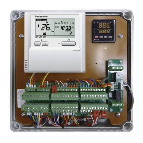
AHU control kit
A L 1
P V
º C
O U T
S V
º C
A T U
S E T
0 – 10V Capacity control
PACi or ECOi/ECO G outdoor unit
Demand control on the outdoor unit managed by external 0–10 V signal.
Control option 1: PAW-280PAH2L
· The system's control is simple: control of actual suction temperature vs. set point
· Control works in the same way as that of any indoor unit
· Fan signal issued by the PCB (OFF while defrosting, for instance)
Control option 2: PAW-280PAH2
· System control by probe located at air intake. Sensor works as a 0–10V control thermostat which manages the set
point temperature. Control to prevent cold draughts.
· All signals as per standard
Control option 3: PAW-280PAH2
· System control by external environment probe. Sensor works as a 0–10V control thermostat which manages the
set point temperature. Enhances efficiency by adjusting capacity to the ambient temperature and enhances
comfort as well.
· All signals as per standard
Control option 4: PAW-280PAH2
· System control by a 0–10V control working from an external BMS that manages the set point for the temperature or
the capacity. Enhances efficiency by adjusting capacity and enhances comfort as well.
· All signals as per standard
258
Main components of mechanical ventilation systems
The main components of a mechanical ventilation system are the
following: Air Handling Unit (AHU), air ducts and air distribution elements.
Exhaust air
External BMS
Air Handling Unit (AHU)
0-10V control
With the 0-10 v demand control the capacity of the outdoor unit can be
controlled by 20 steps.
Input Voltage* (V)
Demand (% of
nominal current)
Indoor unit
start / stop
1) No cut/Stop: AHU system / indoor unit is completely switched OFF.
2) No Limit: No restrictions applied by BMS to AHU system / indoor unit performance (equivalent to "full-load operation" of AHU
system / indoor unit).
Outside air
0
1,0 1,5 2,0 2,5 3,0 3,5 4,0 4,5 5,0 5,5 6,0 6,5 7,0 7,5 8,0 8,5 9,0
No cut
1)
40 45 50 55 60 65 70 75 80 85 90 95 100 105 110 115 120
Stop
1)
Start
Return air
Supply air
9,5
No limit /
Full capacity
2)
Advertisement
Table of Contents

Related Manuals for Panasonic PAW-160MAH2L


Summary of Contents for Panasonic PAW-160MAH2L
- Page 1 Air Handling Unit Kit 5,00-25,00kW for PACi. Compatible with R32 or R410A outdoor units Panasonic AHU Kit, 5,00-25,00kW connected to PACi outdoor unit Main components of mechanical ventilation systems The Air Handling Unit Kit has been developed to better meet customer...
- Page 2 NEW — COMMERCIAL AHU Kit connects PACi outdoor units to Air Handling Units system. The Panasonic AHU Kits offer a wealth of connectivity possibilities so can be easily integrated into many systems. Application: Hotels, offi ces, server rooms or all large buildings where air quality control such as humidity control and fresh air and is needed.
- Page 3 Air Handling Unit Kit Installation Instructions ºC ºC...
- Page 5 Air Handling Unit Kit Installation Instructions Original Installation Instructions (English) July 2019 COPYRIGHT © Panasonic Marketing Europe GmbH 2019. All rights reserved.
-
Page 6: Table Of Contents
Table of Contents General information and safety instructions ............ Introduction ......................... Structure and meaning of notices and symbols .............. Safety instructions ......................Instructions for the safe handling of R32 ................. 1.4.1 Calculating the density limit ..................1.4.2 Preventing leakages ....................1.4.3 Detecting leaks ...................... - Page 7 Wiring layout ........................Wiring system diagrams ..................... Connection of external signal lines................... Test Run ........................ Control ........................Remote controller ....................... Thermostat........................... 7.2.1 Control and display elements..................7.2.2 Operation ........................7.2.3 Initial Settings......................7.2.4 Error Codes......................... 7.2.5 Maintenance and Service ...................
-
Page 8: General Information And Safety Instructions
R410A while others are operated with the new refrigerant R32. Application examples for Panasonic AHU Kits are hotels, offi ces, server rooms or all large build- ings where air quality control such as humidity control and fresh air is needed. -
Page 9: Structure And Meaning Of Notices And Symbols
General information and safety instructions Structure and meaning of notices and symbols Safety notices WARNING This indicates a hazardous situation which, if not avoided, could result in death or serious injury. CAUTION This indicates a hazardous situation which, if not avoided, could result in minor or moderate injury. -
Page 10: Safety Instructions
General information and safety instructions Safety instructions WARNING The following precautions need to be followed strictly, in order to avoid hazardous situations, which could result in death or serious injury. Electric shock or fi re may result from inadequate or incorrect installation or wiring procedures. -
Page 11: Instructions For The Safe Handling Of R32
General information and safety instructions other source of fi re. Incorrect installation can result in falling equipment causing damage, injuries or other accidents. ► Install in a location that is fully strong enough to support the weight of the equipment. ►... -
Page 12: Calculating The Density Limit
General information and safety instructions WARNING The following precautions need to be followed strictly, in order to avoid hazardous situations, which could result in death or serious injury. A fi re or explosion hazard and the generation of poisonous gas may result if R32 refrige- rant gas comes into contact with open fl... - Page 13 General information and safety instructions While there are no fl oor area limitations for refrigerant charges of less than 1.23 kg, the mini- mum fl oor area [A ] for larger refrigerant charge amounts can be calculated by the following formula: ceiling-mounted 2.5 x LFL...
- Page 14 General information and safety instructions the DX coil appliance is installed in an occupied area under the ceiling or in an equivalent position. Refrigerant charge amount (i.e. total of refrigerant at shipment and refrigerant charge amount in the fi eld), specifi ed in kg Maximum refrigerant charge amount, specifi...
- Page 15 General information and safety instructions U-71PZH2E5, U-71PZH2E8, U-100PZH2E5, U-100PZH2E8, U-125PZH2E5, U-125PZH2E8, U-140PZH2E5, U-140PZH2E8 26.0 24.0 * U-71PZH2E5, U-71PZH2E8 22.0 Can not be installed 20.0 18.0 16.0 Can be 14.0 installed 12.0 10.0 Can not be installed ]: refrigerant charge (kg) of the outdoor unit 1.220 2.850...
-
Page 16: Preventing Leakages
General information and safety instructions U-200PZH2E8, U-250PZH2E8 45.0 40.0 35.0 30.0 Can be installed 25.0 20.0 15.0 Can not be installed 10.0 ]: refrigerant charge (kg) of the outdoor unit 1.22 7.80 Elite U-200PZH2E8 U-250PZH2E8 ] (kg) 7.80 1.4.2 Preventing leakages ●... -
Page 17: Detecting Leaks
General information and safety instructions 1.4.3 Detecting leaks ● If a leak is suspected, remove or extinguish all naked fl ames and ventilate the space immediately. ● To search for and detect any refrigerant leaks, never use potential sources of igniti- on like e.g. -
Page 18: Ventilation Theory And Air Handling Units
Ventilation theory and air handling units Ventilation theory and air handling units Purpose of air-conditioning The purpose of air-conditioning is to provide comfortable indoor air conditions for the room oc- cupants and to provide energy saving potentials for the owner. Comfort If room occupants feel “comfortable“... -
Page 19: Mechanical Ventilation Systems
Ventilation theory and air handling units Mechanical ventilation systems Main components of mechanical ventilation systems The main components of a mechanical ventilation system are the following: ● Air handling unit (AHU) ● Air ducts ● Air distribution elements Outside air Exhaust air Return air Supply air... - Page 20 Ventilation theory and air handling units Main types of air handling units Supply type Exhaust type Supply/Exhaust type with cross-fl ow heat exchanger Supply/Exhaust type with mixing chamber...
- Page 21 Connecting AHU systems via the AHU Kit to ECOi/ECO G or PACi outdoor units The following graphic shows an example for connecting a third-party air handling unit via the Panasonic AHU Kit to Panasonic ECOi/ECO G or PACi outdoor units. Air handling unit control by external 0–10 V signal External control...
-
Page 22: Product Description
Product description Product description General description The Panasonic AHU Kits off er a wealth of connectivity possibilities so that they can be easily integrated into many systems. The new AHU Kit has been developed to better meet customer demand: ● Three versions available depending on the required functionality (light, medium or advanced version) ●... -
Page 23: Scope Of Supply
The scope of supply of the AHU Kits depends on the product version (light, medium or ad- vanced) and on the relevant VRF system range. The following table shows an overview of the diff erent scopes of supply. Scope of supply Version Light Medium Advanced PAW-160MAH2L PAW-160MAH2M PAW-160MAH2 PAW-280MAH2L PAW-280PAH2L PAW-280MAH2M PAW-280PAH2M PAW-280MAH2... - Page 24 Product description Medium version: PAW-280PAH2M* Remote controller (CZ-RTC2 / CZ-RTC4**) Terminal board with 6 connectors CZ-CAPBC2 interface (on rear side) * Shown as an example and with transparent front cover removed. ** Depending on AHU Kit generation. PACi accessories Thermistor x2 Thermistor (Refrigerant: E1, E2) (Air: TA)
- Page 25 Product description CZ-CAPBC2 Mini seri-para I/O unit (medium and advanced versions only) ● Easy integration in external AHU control systems and BMS ● Demand control: 40 to 115 % (5 % steps) of nominal current by 0–10 V input signal »...
- Page 26 Product description Additional contacts available ● External humidifi er control (ON/OFF) 230 V AC 3 A » Terminal HU1; HU2. ● External fan control (ON/OFF) 12 V DC » Terminal FD1; FD2. ● External fi lter status signal potential free »...
- Page 27 Product description Lower mounting board Auxiliary transformer Relay Transformer Relay Single motorized valve PCB Relay Single RAP valve control PCB Double RAP valve control PCB3 1 Not available in all versions. 2 For details see “5.4 Terminal block layout”. 3 Depending on the model used, the single RAP valve control PCB (16) or double RAP valve control PCB (17) is mounted in this position.
-
Page 28: System Lineup
Product description System lineup System lineup – ECOi systems Capacity Outdoor unit combination AHU Kit combination U-... PAW-... HP kW all Mini ECOi/ECOi outdoor units 160MAH2(L/M) – – – all Mini ECOi/ECOi 2-pipe and 3-pipe outdoor units 280MAH2(L/M) – – –... - Page 29 Product description System lineup – ECO G systems Capacity Outdoor unit AHU Kit HP kW PAW-160MAH2(L/M) all ECO G outdoor units PAW-280MAH2(L/M) all ECO G 2-way outdoor units all ECO G 2-way outdoor units PAW-560MAH2(L/M) 1 PAW-160MAH2(L/M): ● Like any other standard indoor unit, PAW-160MAH2(L/M) can be installed in combination with all ECO G outdoor units.
-
Page 30: System Overview
Product description System Overview System Overview – ECOi systems Single-connection system AHU Kit enclosure (complete) Thermistor for liquid pipe AHU system (fi eld supplied) Thermistor for gas pipe Remote controller (integrated in AHU Kit enclosure) Thermistor for suction air Outdoor unit Thermistor for discharge air Liquid piping (fi... - Page 31 Product description Multi-connection system Note: The following restrictions apply only if PAW-560MAH2(L) is used alone or in combination with other AHU Kits. For all other AHU Kits and AHU Kit combinations without PAW-560MAH2(L) no such restrictions apply. 1 All AHU heat exchangers belonging to the same refrigerant circuit have to be installed in the same chassis equipped with one single fan motor.
- Page 32 Electronic expansion valve plied) 1 Single-connection system shown here as an example. 2 Multi-connection systems are possible in combination with PAW-160MAH2(L/M) or PAW-280MAH2(L/M). In case of multi-connections with PAW-560MAH2(L/M) further restrictions will apply. For details, please contact your local Panasonic service partner.
- Page 33 Product description System Overview – PACi systems Single-connection system only Strainer (liquid pipe & gas pipe) min. Ø 25.4 mm (fi eld supplied) AHU Kit enclosure (complete) Thermistor for heat exchanger pipe middle (E2) AHU system (fi eld supplied) Thermistor for suction air (TA) Remote controller (integrated in AHU Kit enclosure) Inter-unit wiring Outdoor unit...
-
Page 34: Technical Data
Product description Technical data Technical data – AHU Kit All AHU Kit models Power source V / ph / Hz 220 ... 240 / 1 / 50 Rated current consumption Rated power consumption (max.) 18.0 Dimensions (enclosure) H x W x D 278 x 278 x 180 Net weight Advanced / Medium... - Page 35 Product description Technical data and limitations – ECOi and ECO G systems – R410A AHU Kit HP 30¹ 40¹ AHU Kit model PAW-160MAH2(L/M) PAW-280MAH2(L/M) PAW-560MAH2(L/M) PAW-280MAH2(L/M) + PAW-560MAH2(L/M) + PAW-560MAH2(L/M) PAW-560MAH2(L/M) Nominal cooling capacity 14.0 28.0 56.0 84.0 112.0 Nominal heating capacity 16.0 31.5 63.0...
- Page 36 Product description Technical data and limitations – PACi systems – R410A AHU Kit PAW-280PAH2(L/M) Outdoor unit – PACi Standard U-60PEY2E5 U-71PEY2E5 U-100PEY1E5 U-125PEY1E5 U-100PEY1E8 U-125PEY1E8 U-140PEY1E8 Nominal cooling capacity 10.0 12.5 10.0 12.5 14.0 Nominal heating capacity 10.0 12.5 10.0 12.5 14.0 Piping connections...
- Page 37 AND an ambient air temperature limit above which it may not be possible to pump down the com- plete refrigerant charge (including all additional refrigerant) into the outdoor unit. Note: The AHU DX coil must be designed according to Panasonic specifi cation.
- Page 38 Product description Calculation example for total additional refrigerant charge (R410A) Unit: U-60PE2E5A Pipe length: 40 meter AHU DX coil (supplied by AHU manufacturer): 1,7 dm Refrigerant charge at shipment fi tted for pipe length within 30 m Pipes additional refrigerant charge: 0,04 kg/m AHU DX coil additional refrigerant charge: 0,9 kg/dm Refrigerant charge at shipment is suffi...
- Page 39 Product description Technical data and limitations – PACi systems – AHU Kit PAW-280PAH2(L/M) Outdoor unit – PACi Standard U-60PZ2E5 U-71PZ2E5 U-100PZ2E5 U-125PZ2E5 U-140PZ2E5 U-100PZ2E8 U-125PZ2E8 U-140PZ2E8 Nominal cooling capacity 10.0 12.5 14.0 10.0 12.5 14.0 Nominal heating capacity 10.0 12.5 14.0 10.0 12.5...
- Page 40 AND an ambient air temperature limit above which it may not be possible to pump down the com- plete refrigerant charge (including all additional refrigerant) into the outdoor unit. Note: The AHU DX coil must be designed according to Panasonic specifi cation.
- Page 41 Product description Calculation example for total additional refrigerant charge (R32) Unit: U-60PZ2E5 Pipe length: 40 meter AHU DX coil (supplied by AHU manufacturer): 1,7 dm Refrigerant charge at shipment fi tted for pipe length within 30 m Pipes additional refrigerant charge: 0.035 kg/m AHU DX coil additional refrigerant charge: 0.83 kg/dm Refrigerant charge at shipment is suffi...
-
Page 42: Installation
Installation Installation Installation of AHU Kit WARNING Electric shock from live power supply cords Electric shock may result from contact with live power supply cords. ► Wiring installation must only be performed by a qualifi ed electrician. ► Before starting to work on any machines or devices, always switch off the power sup- ply and lock it in switched-off... - Page 43 Installation enclosure. 4. Mount the backside of the enclosure to the wall or surface using fi eld-supplied fi xing screws inserted through the previously prepared holes at each corner.
- Page 44 Installation NOTICE Signal errors through noise from live power supply cords Power supply cords can generate noise, which may cause signal errors, if they are run in close vicinity to any low-voltage control wiring. ► Keep 230 V AC power supply wiring apart from the low-voltage control wiring for sen- sors etc.
-
Page 45: Installation Of Refrigerant Piping
Installation Installation of refrigerant piping When installing the refrigerant piping, the following limitations and restrictions need to be observed: ● Maximum actual and equivalent piping length ● Maximum branch pipe length to AHU Kit ● Maximum branch pipe length diff erence (between longest and shortest piping from the fi... - Page 46 Installation When installing the expansion valve, the following limitations and restrictions need to be observed: ● Wires must not be put out of equipments. ● Wires must not be cut and connector of wires must not be detached. ● The distance from AHU heat exchanger must not exceed 6 m. ●...
-
Page 47: Installation Of Thermistors
Installation Installation of thermistors NOTICE Damage to the thermistor wires Exposing the wires of thermistors to the outside and/or to direct sunlight might damage the wires and should therefore be avoided. ► Attach the AHU Kit either directly to the Air Handling Unit or to a wall nearby and make sure that it is not exposed to direct sunlight. -
Page 48: Installation Of Thermistor On Gas Pipe
Installation ● The thermistor wire must be inserted drooped in the AHU body with the drooping wire being close to the AHU Kit. Inside of AHU AHU Kit Drooping wire Important If there are multiple heat exchangers in one ECOi system, an individual thermistor must be installed for each heat exchanger. -
Page 49: Installation Of Thermistor On Liquid Pipe
Installation 4. Fix thermal insulation and wiring with two bands. Then, run the wire downwards in a loop, to avoid putting tension to it. For PAW-280MAH2(L/M) and PAW-560MAH2(L/M) 1. Upon delivery, for PAW-280MAH2(L/M) and PAW-560MAH2(L/M) there is a sensor sleeve soldered to the gas pipe after the expansion valve: Insert the sensor together with some heat sink paste into the sensor sleeve. -
Page 50: Installation Of Thermistor On Heat Exchanger Pipe Middle
Installation 4.4.3 Installation of thermistor on heat exchanger pipe middle Installation of thermistor on heat exchanger pipe middle – PACi systems Mount “E2” thermistor to the heat exchanger pipe middle according to the following instructions. 1. Attach the heat exchanger pipe middle thermistor in the middle of each pass-line (pipe) in the heat exchanger. -
Page 51: Installation Of Thermistor For Suction And Discharge Air Stream
Installation 4.4.4 Installation of thermistor for suction and discharge air stream Mount the suction and discharge air thermistors according to the following instructions. 1. For ECOi, ECO G and PACi systems, attach the suction air thermistor (TA) to the position where air suction temperature can be measured. - Page 52 Installation JP001 JP001 JP001 Standard – Elite – Elite – U-100PZ2E5 U-71PZH2E5 U-71PZH2E8 U-125PZ2E5 U-100PZH2E5 U-100PZH2E8 U-140PZ2E5 U-125PZH2E5 U-125PZH2E8 U-140PZH2E5 U-140PZH2E8 2. Place a NOTE label, which indicates that the jumper wire has been cut, in the following desi- gnated areas on the outdoor unit. NOTES* * Position of designated area for NOTES label depends on...
- Page 53 Installation To connect the remote controller and subsequently change the relevant settings, complete the following steps: 1. Connect the maintenance remote controller to the blue 3-pole CN-RC plug on the main PCB of the PACi outdoor unit using the optional special service wiring CV6242785082 or PAW- MRC (as an alternative, you can also use any unused indoor unit connector (E3, PNL, FS, RC) or temporarily disconnect one of those wires from the AHU kit itself).
- Page 54 Installation Standard – Outdoor unit maintenance CN-RC U-100PZ2E5 remote controller U-125PZ2E5 U-140PZ2E5 Optional special service wiring (CV6242785082 or PAW-MRC) Standard wired remote controller CZ-RTC4 Standard – Outdoor unit maintenance CN-RC U-100PZ2E8 remote controller U-125PZ2E8 U-140PZ2E8 Optional special service wiring (CV6242785082 or PAW-MRC) Standard wired remote controller...
- Page 55 Installation 2. Verify that the display of the maintenance remote controller is working. 3. Simultaneously press the “Spanner” and “Leave Home” buttons for at least 4 seconds. Depending on which model you are using as maintenance remote controller, CZ-RTC2 or CZ-RTC4, the buttons look diff...
- Page 56 Installation 3. Press the Temperature “UP” button (▲) just once shortly, in order to scroll to parameter “11”. 4. With the Timer “UP” and “DOWN” buttons (▲▼) modify the parameter value according to the following table: PACi outdoor unit model Setting for AHU Kit parameter “11”...
-
Page 57: Electrical Wiring
Electrical Wiring Electrical Wiring General precautions on wiring WARNING Electric shock from live power supply cords Electric shock may result from contact with live power supply cords. ► Wiring installation must only be performed by a qualifi ed electrician. ► Before starting to work on any machines or devices, always switch off the power sup- ply and lock it in switched-off... -
Page 58: Recommended Wire Lengths And Diameters
Electrical Wiring Recommended wire lengths and diameters Important ● The letter coding (A to F) used in the following tables refers to the wiring system diagrams in the next section. ● For information on “(A) Power supply of outdoor unit” refer to the “Installation Inst- ructions“... - Page 59 Electrical Wiring 4. Place the wire-end sleeve into the socket on the connector and replace and tighten the re- moved terminal screw using a fl at-blade screwdriver. Screw Special washer Screw and special washer Terminal plate Wire-end sleeve Wire Wire Wire-end sleeve Shielded wire 1.
-
Page 60: Terminal Board Layout
Electrical Wiring Terminal board layout Terminal layout – Main terminal board (CR-UXRP71B-P) = Input or Output necessary to connect. = Input or Output can be connected if required. Section A Connections Name In / Out Allocation Function Description Alarm Signal External Potential: Alarm Signal max. - Page 61 Electrical Wiring Section C Connections Name In / Out Allocation Function Comment Recirculat. Operation Heating Operation Cooling Operation Status Outputs Internal Potential: 12 V DC Thermostat ON Defrost Operation Potential for ON2 to ON6 (12 V DC) Potential for DI1 to DI3 2 types of usage: Digital Inputs a) Potential-free:...
- Page 62 Electrical Wiring Section F Connections Name In / Out Allocation Function Comments M2-6 Advanced & Medium: Activation of Remove bridge for use of demand (FREE) demand control control (if bridge is intact and in place, Advanced & Medium: Activation of temperature setpoint control is active) M2-5 demand control...
- Page 63 Electrical Wiring Terminal layout – CZ-CAPBC2 / ACC-SP1A (for advanced and medium ver- sions only) CZ-CAPBC2 interface, terminal block CN1 Connections Polarity Name Allocation Function Comments By factory default connected 12 V power supply (12V) – By factory default connected By factory default connected Remote control line A (Start)
- Page 64 (Start) (12V) Electrical Wiring LINE A (U.H.J1.A.J2) (Alarm) CZ-CAPBC2 interface, terminal block CN2 Connections Name Allocation Function Comments LINE B By factory default connected to (T.G) terminal contacts Digital output 1 (Start output) By factory default connected to (Start) (12V) terminal contacts By factory default connected to LINE A...
- Page 65 (Start) (12V) Electrical Wiring LINE A Input 1 (DI1) Input 2 (DI2) Input 3 (DI3) Voltage of NO contact: open ► close close ► open open ► close close ► open open ► close close ► open (U.H.J1.A.J2) static / pulses (Alarm) –...
-
Page 66: Wiring Layout
Electrical Wiring Wiring layout Wiring layout – ECOi and ECO G systems PAW-160MAH2L t° t° t° t°... - Page 67 Electrical Wiring PAW-160MAH2M t° t° t° t°...
- Page 68 Electrical Wiring PAW-160MAH2 t° t° t° t°...
- Page 69 Electrical Wiring PAW-280MAH2L t° t° t° t°...
- Page 70 Electrical Wiring PAW-280MAH2M t° t° t° t°...
- Page 71 Electrical Wiring PAW-280MAH2 t° t° t° t°...
- Page 72 Electrical Wiring PAW-560MAH2L t° t° t° t°...
- Page 73 Electrical Wiring PAW-560MAH2M t° t° t° t°...
- Page 74 Electrical Wiring PAW-560MAH2 t° t° t° t°...
- Page 75 Electrical Wiring Wiring layout – PACi systems PAW-280PAH2L t° t° t°...
- Page 76 Electrical Wiring PAW-280PAH2M t° t° t°...
- Page 77 Electrical Wiring PAW-280PAH2 t° t° t°...
-
Page 78: Wiring System Diagrams
Electrical Wiring Wiring system diagrams Wiring system diagram – ECOi systems AHU Kit (No. 1) Power supply Outdoor unit 220 – 240V ~50/60Hz INV unit Ground Power supply Remote 380 – 415V, 3 N~, 50Hz controller Ground Ground Ground Ground AHU Kit (No. - Page 79 Electrical Wiring Wiring system diagram – PACi systems For single-phase outdoor units AHU Kit Power supply Outdoor unit 220 – 240V ~50/60Hz INV unit Power supply Ground 220 – 240V ~50/60Hz Remote controller Ground Ground Ground Ground For three-phase outdoor units AHU Kit Power supply Outdoor unit...
- Page 80 Electrical Wiring 6. Use the standard power supply cables for Europe (such as H05RN-F or H07RN-F which conform to CENELEC(HAR) rating specifi cations) or use the cables based on IEC standard (245 IEC57, 245 IEC66). 7. When linking the outdoor units in a network, the following rules for bus terminators must be observed.
-
Page 81: Connection Of External Signal Lines
Electrical Wiring 11. In case of a multiple AHU Kit combination within one refrigerant system, those kits must share the same AHU housing including fan, and they have to be “group- wired” and operate as a single group. In this case you have to disconnect the included remote controllers and CZ-CAPBC2 boards (ACC-SP1A PCB) except for one each. - Page 82 Electrical Wiring Method A: For standard fan control For systems with standard fan control, the external signal lines can simply be connected to the contacts provided by the AHU Kit. The following installation requirements must be observed: ● Blower signal output: terminals D4 (IZ-5) and D5 (IZ-3). Blower protection input: terminals D6 (OP3) and D7 (2Z-7).
- Page 83 Electrical Wiring If uninterrupted fan operation is needed and cold draft air is avoided for example by some internal bypass etc., the defrost signal (contacts C5 (ON1) and C6 (ON2)) can be used with an additional fi eld supplied relay. Blower protection input If a switch opens, an alarm “P01”...
- Page 84 Electrical Wiring Electric circuit example – PACi systems Single-connection system AHU Kit Field-supplied 10P Connector Blower signal Blower output signal Method B: For multi-step or inverter mode fan control by external BMS When the AHU fan is controlled by an external building management system in a multi-step or inverter mode (e.g.
- Page 85 Electrical Wiring Electric circuit example including a timer and air fl ow switch External control system AHU Kit ºC ºC Air Handling Unit (AHU) PACi or ECOi/ECO G outdoor unit Air fl ow switch Timer PAW-T10: Main terminal board: Terminals I (1) and I (2) Terminals D4 and D5...
-
Page 86: Test Run
Test Run Test Run After installation and before operation of the system, perform a test run according to the Test Run section in the Installation Instructions of the relevant outdoor unit. If alarm messages are indicated on the outdoor unit PCB (by blinking LEDs) or on the wired remote controller, refer to the Alarm Messages section in the Installation Instructions for the relevant outdoor unit. -
Page 87: Control
Control Remote controller The standard Panasonic wired remote controller CZ-RTC2 / CZ-RTC4 is an integral part of the AHU Kit. All control and setting operations for the ECOi, ECO G or PACi system can be per- formed on this remote controller. - Page 88 Control value is shown on the PV display and the currently set temperature value is shown on the SV display. Control voltage switched on Software version view (factory setting) Input specifi cation view (factory setting) Measuring range (factory setting) PV = lower limit SV = upper limit The two displays fi...
- Page 89 Control Changing values in the “Parameter” menu To change the values of control parameters, perform the following steps: 1. Press and hold the button for approximately 3 seconds to enter the “Parameter” menu. 1 x for 3 sec. The PV display shows “ALI”, while the current setting in the SV display is blinking. Note: After 30 seconds of idleness, the display automatically returns from parametrization view to normal view.
- Page 90 Control Parameter menu Parameter Parameter name Setting Description code range Inactive – Hysteresis 0 ... 50 Switching difference relative to the set value, unilateral (i. e. the value is added either below (“heating mode”) or above (“cooling mode”) the set value) Proportional band (P) 000 ...
- Page 91 Control NOTICE System heat-up to temperatures signifi cantly exceeding the set temperature value During Auto-Tuning mode the system may heat up to temperatures signifi cantly exceeding the set temperature value and may cause damage to sensitive applications. ► Before starting the Auto-Tuning mode, the set temperature value should be reduced to an uncritical value.
- Page 92 Switching from 0–10 V to 2–10 V output signals The voltage range for the output signals on terminals 6–7 is factory-set to 0–10 V. Switching the voltage range from 0–10 V to 2–10 V is possible. However, Panasonic recom- mends to keep the factory setting.
-
Page 93: Initial Settings
Control 3. Confi rm the new setting by pressing the button. 1 x briefl y The PV display now shows “nun”, while the SV display now shows “3”. 4. Press the button repeatedly to select the entry “AO”. repeatedly 5. Use the buttons to change the value to either “1”... - Page 94 Control 4. On the thermostat, change the set temperature value (T ) as required (see “7.2.2 Operati- on – Changing the set temperature value”). In this case, the set temperature value represents the desired room supply air temperature. 5. On the AHU kit’s terminal connector of section F, remove the jumper (JP1) between terminals “M2-5”...
- Page 95 Control 6. Remove the AHU Kit’s upper mounting board. 7. On the CZ-CAPBC2 PCB (ACC-SP1A), located on the rear side of the upper mounting board inside the AHU Kit enclosure, make sure that switches S1 to S4 are set as follows: a.
- Page 96 Control d. S4: Set to “0–10 V“. 8. Restore and fasten the upper mounting board in its original position, and close the AHU Kit enclosure again (see “4.1 Installation of AHU Kit“ – step 5). Case 3: 0–10 V demand control by an external BMS (available in medium and advanced version only) To set the CZ-CAPBC2 PCB (ACC-SP1A) for 0–10 V demand control by an external building management system (BMS), perfom the following steps:...
- Page 97 Control c. On the terminal connector of Section C, located on the upper mounting board inside the AHU Kit enclosure (see diagram below), connect the digital inputs (DI) as follows: ● Heating start to COM and DI1 ● Cooling start to COM and DI2 ●...
-
Page 98: Error Codes
Control 7.2.4 Error Codes Error Code Meaning Sensor breakage or polarity inversion. Measured value is above the valid upper limit. Sensor short-circuit or polarity inversion. Measured value is below the valid lower limit. 7.2.5 Maintenance and Service In normal operation, the thermostat is maintenance-free. To prolong its lifecycle, the following precautions should be observed: ●... - Page 100 Notes:...
- Page 101 Notes:...
- Page 102 www.aircon.panasonic.eu...
Need help?
Do you have a question about the PAW-160MAH2L and is the answer not in the manual?
Questions and answers