Table of Contents
Advertisement
Quick Links
Advertisement
Table of Contents

Related Manuals for FAAC E700


Summary of Contents for FAAC E700
- Page 1 E 700 E 700...
-
Page 2: Table Of Contents
• conforms to the essential safety requirements of the following EEC directives: 2006/95/EC Low Voltage Directive 2004/108/EC Electromagnetic Compatibility Directive Additional information: This product underwent a test in a typical, uniform configuration (all products made by FAAC S.p.A) Bologna, 01 Mars 2008. The Managing Director A. Bassi WARNINGS •... -
Page 3: Box Layout
(Fig. 3); they can also be removed and re-positioned in order to enable the lid to open to the right or left. The box contains the E700 electronic unit and the devices to power it. It must therefore be handled with care during all installation stages, to avoid damaging its components. -
Page 4: Warnings
- To avoid any electrical disturbance, use separate sheaths or a screened cable (with the screen earthed). 3 LAYOUT AND CONNECTIONS (PARTIAL OPENING) (TOTAL OPENING) 230 Vac 50Hz 115 Vac 60Hz Fig. 7 The power supply is related to the E700 purchased version. -
Page 5: Technical Specifications
TECHNICAL SPECIFICATIONS 4.2 DESCRIPTION OF TERMINAL-BOARDS Terminal and/or 230Vac (+6% -10%) - 50Hz Description Device connected Power supply voltage terminal-board 115Vac (+6% -10%) - 60Hz Power supply for Absorbed power +24V accessories Motor max. load 150W x 2 Negative Accessories max. current 250 mA Device with NC Device with NC... -
Page 6: Start-Up
7. START-UP 7.4 TIME LEARNING - SET-UP 7.1 LEDS CHECK Before any moviment is executed, the Encoders must be wired as explained on chapter 8.1 The following table shows the status of the LEDs in relation to page 6. the status of the inputs (the closed at rest automated system Before any manoeuvre is executed, a SETUP condition is shown in bold). -
Page 7: Installation Of Bus Accessories
If the A Logic was selected, the board begins to count Tab. 3 - Encoder connection and LED status the pause time (max 10 min) and, after the required time LIGHTED FLASHING has elapsed, give an OPENING pulse to continue the Power ON procedure. -
Page 8: Memory Storage Of Bus Accessories
8.3 MEMORY STORAGE OF BUS ACCESSORIES You can add the BUS photocells to the system at any time, simply by memory-storing them on the board, observing the following procedure: Install and program the accessories using the required address (see paragraph 8.2 ) Cut power to the board. -
Page 9: Memory Storage Of Ds Radio Controls
The automated system performs one opening operation. Make sure that the automated system is free of any obstacle created by persons or things. To add other radio controls, transfer the code of the memory-stored push-button of the radio control to the relevant push-button of the radio controls to be added, observing the following procedure. -
Page 10: Remote Memory Storage Of Lc Radio Controls
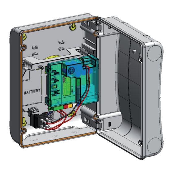
9.3.1 REMOTE MEMORY STORAGE OF LC RADIO 10.1 BATTERY KIT CONTROLS The buffer battery kit was built for insertion inside the control Other radio controls can be remotely stored only with the board support. LC radio controls, i.e. without using the LOGIC-SPEED-SETUP This support (Fig.11 ref. -
Page 11: Logic Tables
12 LOGIC TABLES... - Page 12 Les descriptions et les illustrations du présent manuel sont fournies à titre indicatif. FAAC se réserve le droit d’apporter à tout moment les modifications qu’elle jugera utiles sur ce produit tout en conservant les caractéristiques essentielles, sans devoir pour autant mettre à...
Need help?
Do you have a question about the E700 and is the answer not in the manual?
Questions and answers