Parker Compax3S Series Installation Manual
Single axis devices
Hide thumbs
Also See for Compax3S Series:
- Manual (46 pages) ,
- Installation manual (44 pages) ,
- Quick reference manual (20 pages)
Table of Contents
Advertisement
Quick Links
Single axis devices
Compax3S Installation Manual
Single axis devices
We reserve the right to make technical changes.
The data correspond to the current status at the time of printing.
Paper version
Release as from R09-63
04.08.14 15:37
Electromechanical Automation
C3Manager-Compax3S
Unterlagen / Software
user guides / tools
manuels / tools:
Compax3 - DVD (english, deutsch, français)
+
StartUp Guide (english / deutsch)
Compax3S Installations-Handbuch deutsch
Compax3S Installation Manual english
Manuel technique Compax3S français
192-120102 N19 June 2014
192-120102 N19
June 2014
Advertisement
Table of Contents

Related Manuals for Parker Compax3S Series


Summary of Contents for Parker Compax3S Series
- Page 1 Single axis devices Electromechanical Automation Compax3S Installation Manual Single axis devices Paper version C3Manager-Compax3S Unterlagen / Software user guides / tools manuels / tools: Compax3 - DVD (english, deutsch, français) StartUp Guide (english / deutsch) Compax3S Installations-Handbuch deutsch ...
- Page 2 Parker Hannifin GmbH - registered office: Bielefeld HRB 35489 Management Board: Ellen Raahede Secher, Dr.-Ing. Gerd Scheffel, Günter Schrank, Kees Veraart - Vorsitzender des Aufsichtsrates: Hansgeorg Greuner Parker Hannifin Manufacturing Srl • SSD SBC • Electromechanical Automation • Via Italy: Gounod, 1 I-20092 Cinisello Balsamo (MI), Italy Tel.: +39 (0)2 361081 •...
-
Page 3: Notes On The Documents Supplied
Please use always the latest C3 ServoManager version. Parker Integrated Furthermore, the "Parker Integrated Engineering Tool", a software tool for the project management of several Parker Motion Control products, can be found on the C3 Engineering Tool DVD. Several axes are managed in a common project. The Compax3 ServoManager is integrated per "Plug &... -
Page 4: C3 Servomanager
Notes on the Documents Supplied Single axis devices C3 ServoManager Installation of the C3 The Compax3 ServoManager can be installed directly from the Compax3 DVD. ServoManager Click on the corresponding hyperlink resp. start the installation program "C3Mgr_Setup_V..exe" and follow the instructions. PC requirements Recommendation: Operating system:... -
Page 5: Table Of Contents
C3 ServoManager Parker EME Contents 1. Notes on the Documents Supplied ............3 C3 ServoManager ..................4 2. Introduction ..................... 6 Device assignment .................. 6 Scope of delivery ..................6 Type specification plate ................7 Packaging, transport, storage ..............8 Safety instructions ................... -
Page 6: Introduction
Introduction Single axis devices 2. Introduction In diesem Kapitel finden Sie Device assignment ......................6 Scope of delivery ....................... 6 Type specification plate ..................... 7 Packaging, transport, storage .................... 8 Safety instructions ......................9 Warranty conditions ......................11 Conditions of utilization ....................12 EC declaration of conformity .................... -
Page 7: Type Specification Plate
Type specification plate Parker EME Type specification plate The present device type is defined by the type specification plate (on the housing): Compax3 - Type specification plate (example): Explanation: Type designation: The complete order designation of the device (2, 5, 6, 9, 8). -
Page 8: Packaging, Transport, Storage
Introduction Single axis devices Packaging, transport, storage Packaging material and transport Caution! The packaging material is inflammable, if it is disposed of improperly by burning, lethal fumes may develop. The packaging material must be kept and reused in the case of a return shipment. Improper or faulty packaging may lead to transport damages. -
Page 9: Safety Instructions
Safety instructions Parker EME Safety instructions In diesem Kapitel finden Sie General hazards ........................ 9 Safety-conscious working ....................9 Special safety instructions ....................10 2.5.1. General hazards General Hazards on Non-Compliance with the Safety Instructions The device described in this manual is designed in accordance with the latest technology and is safe in operation. -
Page 10: Special Safety Instructions
Introduction Single axis devices 2.5.3. Special safety instructions Caution! Due to movable machine parts and high voltages, the device can pose a lethal danger. Danger of electric shock in the case of non-respect of the following instructions. The device corresponds to DIN EN 61800-3, i.e. it is subject to limited sale. -
Page 11: Warranty Conditions
Warranty conditions Parker EME Please note in the event Forming the capacitors of storage >1 year: Forming the capacitors only required with 400VAC axis controllers and PSUP mains module If the device was stored longer than one year, the intermediate capacitors must be... -
Page 12: Conditions Of Utilization
Introduction Single axis devices Conditions of utilization In diesem Kapitel finden Sie Conditions of utilization for CE-conform operation ............12 Conditions of utilization for UL certification Compax3S ............ 14 Current on the mains PE (leakage current) ..............15 Supply networks ......................15 2.7.1. - Page 13 400 VAC / 0.740 mH certified in accordance with EN 61558-1 bzw. 61558-2-2 We offer the mains filter as an accessory: LIR01/01 Make sure to use only the accessories recommended by Parker Accessories: Connect all cable shields at both ends, ensuring large contact areas! Warning: This is a product in the restricted sales distribution class according to EN 61800-3.
-
Page 14: Conditions Of Utilization For Ul Certification Compax3S
Introduction Single axis devices 2.7.2. Conditions of utilization for UL certification Compax3S UL certification for Compax3S conform to UL: according to UL508C Certified E-File_No.: E235342 The UL certification is documented by a "UL" logo on the device (type specification plate). “UL”... -
Page 15: Current On The Mains Pe (Leakage Current)
Conditions of utilization Parker EME 2.7.3. Current on the mains PE (leakage current) This product can cause a direct current in the protective lead. If a residual current device (RCD) is used for protection in the event of direct or indirect contact, only a type B (all current sensitive) RCD is permitted on the current supply side of this product . -
Page 16: Ec Declaration Of Conformity
Introduction Single axis devices EC declaration of conformity 192-120102 N19 June 2014... -
Page 17: Compax3 Device Description
State of delivery Parker EME 3. Compax3 device description In diesem Kapitel finden Sie State of delivery ....................... 17 Meaning of the status LEDs - Compax3 axis controller ............ 17 Mounting and dimensions ....................18 Connections of Compax3S ....................22 Signal interfaces ...................... -
Page 18: Mounting And Dimensions
Compax3 device description Single axis devices Mounting and dimensions In diesem Kapitel finden Sie Mounting and dimensions Compax3S0xxV2 ..............18 Mounting and dimensions Compax3S100V2 and S0xxV4..........19 Mounting and dimensions Compax3S150V2 and S150V4 ..........20 Mounting and dimensions Compax3S300V4 ..............21 3.3.1. -
Page 19: Mounting And Dimensions Compax3S100V2 And S0Xxv4
Mounting and dimensions Parker EME 3.3.2. Mounting and dimensions Compax3S100V2 and S0xxV4 Mounting: 3 socket head screws M5 Stated in mm Please respect an appropriate mounting gap in order to ensure sufficient convection: At the side: 15mm At the top and below: at least 100mm ... -
Page 20: Mounting And Dimensions Compax3S150V2 And S150V4
Compax3 device description Single axis devices 3.3.3. Mounting and dimensions Compax3S150V2 and S150V4 Mounting: 4 socket head screws M5 Stated in mm Please respect an appropriate mounting gap in order to ensure sufficient convection: At the side: 15mm At the top and below: at least 100mm ... -
Page 21: Mounting And Dimensions Compax3S300V4
Mounting and dimensions Parker EME 3.3.4. Mounting and dimensions Compax3S300V4 Mounting: 4 socket head screws M5 Stated in mm Please respect an appropriate mounting gap in order to ensure sufficient convection: At the side: 15mm At the top and below: at least 100mm ... -
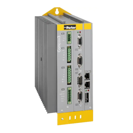
Page 22: Connections Of Compax3S
Compax3 device description Single axis devices Connections of Compax3S In diesem Kapitel finden Sie Compax3S connectors ....................22 Connector and pin assignment C3S................. 23 Control voltage 24VDC / enable connector X4 C3S ............25 Motor / Motor brake C3S connector X3 ................26 Compax3Sxxx V2 ...................... -
Page 23: Connector And Pin Assignment C3S
Connections of Compax3S Parker EME Caution - Risk of Electric Shock! Always switch devices off before wiring them! Dangerous voltages are still present until 10 min. after switching off the power supply. Caution! When the control voltage is missing there is no indication whether or not high voltage supply is available. - Page 24 Compax3 device description Single axis devices The fitting of the different plugs depends on the extension level of Compax3. In part, In detail: the assignment depends on the Compax3 option implemented. Compax3 1AC X20/1 X10/1 X10/1 X10/1 Power supply RS485 +5V RS485 +5V EnableRS232 0V X20/2...
-
Page 25: Control Voltage 24Vdc / Enable Connector X4 C3S
Connections of Compax3S Parker EME 3.4.3. Control voltage 24VDC / enable connector X4 C3S Description Line cross sections: +24V (supply) minimum: 0.25mm Gnd24V maximum: 2.5mm Enable_in (AWG: 24 ... 12) Enable_out_a Enable_out_b Control voltage 24VDC Compax3S and Compax3H Controller type... -
Page 26: Motor / Motor Brake C3S Connector X3
Compax3 device description Single axis devices 3.4.4. Motor / Motor brake C3S connector X3 Designation Motor cable lead designation* U / L1 / C / L+ U (motor) V / L2 V (motor) W / L3 / D / L- W (motor) YE / GN YE / GN... -
Page 27: Compax3Sxxx V2
Connections of Compax3S Parker EME 3.4.5. Compax3Sxxx V2 In diesem Kapitel finden Sie Main voltage supply C3S connector X1 ................27 Braking resistor / high voltage DC C3S connector X2 ............28 3.4.5.1 Main voltage supply C3S connector X1 Device protection By cyclically switching on and off the power voltage, the input current limitation can be overloaded, which will cause a device error. - Page 28 Compax3 device description Single axis devices The 3AC V2 devices must only be operated with three phases! Caution! Caution - Risk of Electric Shock! Always switch devices off before wiring them! Dangerous voltages are still present until 10 min. after switching off the power supply.
-
Page 29: Compax3Sxxx V4
Connections of Compax3S Parker EME 3.4.6. Compax3Sxxx V4 In diesem Kapitel finden Sie Power supply connector X1 for 3AC 400VAC/480VAC-C3S devices ....... 29 Braking resistor / high voltage supply connector X2 for 3AC 400VAC/480VAC_C3S devices Connection of the power voltage of 2 C3S 3AC devices ..........30 3.4.6.1... - Page 30 Compax3 device description Single axis devices Braking operation Compax3SxxxV4 3AC Controller type S015V4 S038V4 S075V4 S150V4 S300V4 Capacity / storable energy 400V / 235µF 235µF 470µF 690µF 1230µF 480V 37 / 21 Ws 37 / 21 Ws 75 / 42 Ws 110 / 61 Ws 176 / 98 Ws 100 Ω...
-
Page 31: Signal Interfaces
Signal interfaces Parker EME Signal interfaces In this chapter you can read about: RS232 / RS485 interface (plug X10) ................31 Resolver / Feedback (connector X13) ................32 Analogue / encoder (plug X11) ..................34 Digital inputs/outputs (plug X12) ..................35 Optional input/output cards .................... -
Page 32: Resolver / Feedback (Connector X13)
Compax3 device description Single axis devices 3.5.2. Resolver / Feedback (connector X13) Assignment with feedback F10 (Resolver) PIN X13 Feedback /X13 High Density /Sub D Resolver (F10) factory use factory use REF-Resolver+ +5V (for temperature sensor) factory use SIN- SIN+ factory use Tmot* COS-... - Page 33 Signal interfaces Parker EME Assignment with feedback F12 (EnDat) PIN X13 Feedback /X13 High Density /Sub D EnDat 2.1 & 2.2 with EnDat 2.1 fully digital EnDat 2.2 fully digital incremental track (Endat21) (Endat02, Endat22) (Endat01, Endat02) (cable length max. 90 m) (cable length max.
-
Page 34: Analogue / Encoder (Plug X11)
Compax3 device description Single axis devices 3.5.3. Analogue / encoder (plug X11) PIN X11 Reference High Density Sub D Encoders +24V (output) max. 70mA Ain1 -; analog input - (14Bits; max. +/-10V) D/A monitor channel 1 (±10V, 8-bit resolution) D/A monitor channel 0 (±10V, 8-bit resolution) +5 V (output for encoder) max. -
Page 35: Digital Inputs/Outputs (Plug X12)
Signal interfaces Parker EME 3.5.4. Digital inputs/outputs (plug X12) Pin X12 Input/output I/O / X12 High density/Sub D Output +24 V DC output (max. 340mA) Output 0 (max. 100 mA) Output 1 (max. 100mA) Output 2 (max. 100mA) Output 3 (max. 100mA) -
Page 36: Optional Input/Output Cards
Compax3 device description Single axis devices 3.5.5. Optional input/output cards In this chapter you can read about: Digital input/output option M12 (I12) ................36 M21 analog input option ....................37 Options M10, M11, M12 and M21 can only be used alternatively. With Compax3 technology functions T20 and T70, option M21 is always integrated. - Page 37 Signal interfaces Parker EME 3.5.5.2 M21 analog input option Connector assignment Option M21 X20 X20: Current inputs (0 ... 20 mA) Name Function Internal input channel +24Vout Sensor supply 0 (output) in0+ Current input 0 + (0 ... 20 mA)
- Page 38 Compax3 device description Single axis devices Connector assignment Option M21 X21 X21: Voltage inputs (-10 V... +10 V) Name Function Internal input channel +24Vout Sensor supply 3 (output) in3 + Voltage input 3 + (-10 V... +10 V) Sensor supply 3 (output) in3 - Voltage input 3 - (-10...
-
Page 39: Technical Characteristics
Signal interfaces Parker EME 4. Technical Characteristics Mains connection Compax3S0xxV2 1AC Controller type S025V2 S063V2 Continuous working voltage Single phase 230VAC/240VAC 80-253VAC / 50-60Hz Receiver current consumption 6Arms 13Arms Maximum fuse rating per device 10 A (automatic 16A (automatic circuit... - Page 40 Technical Characteristics Single axis devices Output data Compax3S1xx at 3*230VAC/240VAC Controller type S100V2 S150V2 Output voltage 3x 0-240V 3x 0-240V Nominal output current 10Arms 15Arms Pulse current for 5s 20Arms 30Arms Power 4kVA 6kVA Switching frequency 16kHz 8kHz Power loss for In 130W Output data Compax3Sxxx at 3*400VAC Controller type...
- Page 41 Signal interfaces Parker EME Supported Motor and Feedback Systems Motors Sinusoidally commutated synchronous motors Direct drives Maximum electrical turning frequency: 1000Hz* Linear motors Max. velocity on 8 pole motors: 15 000min Torque motors General max. speed: ...
- Page 42 Technical Characteristics Single axis devices Motor holding brake output Motor holding brake output Compax3 Voltage range 21 – 27VDC Maximum output current (short circuit 1.6A proof) Safety technology Compax3S Safe torque-off in accordance with EN For implementation of the “protection ...
- Page 43 Signal interfaces Parker EME Environmental conditions Compax3S and Compax3H General ambient conditions In accordance with EN 60 721-3-1 to 3-3 Climate (temperature/humidity/barometric pressure): Class 3K3 Permissible ambient temperature: Operation 0 to +45 °C class 3K3 storage –25 to +70 °C...
-
Page 44: Index
Index Single axis devices 5. Index Additional conditions of utilization • 13 Notes on the Documents Supplied • 3 Analogue / encoder (plug X11) • 34 Assignment of the X22 connector • 36 Optional input/output cards • 36 Braking resistor • 28 Packaging, transport, storage •...
Need help?
Do you have a question about the Compax3S Series and is the answer not in the manual?
Questions and answers