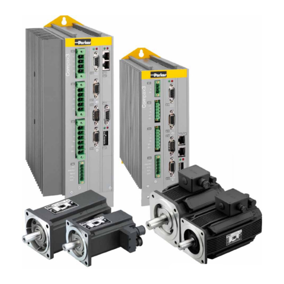
Parker compax3s Installation Manual
Single axis devices
Hide thumbs
Also See for compax3s:
- Manual (46 pages) ,
- Installation manual (44 pages) ,
- Quick reference manual (20 pages)
Table of Contents
Advertisement
Quick Links
Download this manual
See also:
Quick Reference Manual
Compax3
Compax3S Installation Manual
Single axis devices
We reserve the right to make technical changes.
The data correspond to the current status at the time of printing.
Electromechanical Automation
Paper version
Release R09-10
13.12.10 13:24
C3Manager-Compax3S
Unterlagen / Software
user guides / tools
manuels / tools:
Compax3 - DVD (english, deutsch, français)
+
StartUp Guide (english / deutsch)
Compax3S Installations-Handbuch deutsch
Compax3S Installation Manual english
Manuel technique Compax3S français
192-120102 N16 December 2010
Advertisement
Table of Contents

Related Manuals for Parker compax3s


Summary of Contents for Parker compax3s
- Page 1 / tools: Compax3 - DVD (english, deutsch, français) StartUp Guide (english / deutsch) Compax3S Installations-Handbuch deutsch Compax3S Installation Manual english Release R09-10 Manuel technique Compax3S français We reserve the right to make technical changes. 13.12.10 13:24 192-120102 N16 December 2010 The data correspond to the current status at the time of printing.
- Page 2 Tel.: +44 (0)1202 606300 • Fax: +44 (0)1202 606301 E-mail: sales.automation@parker.com mailto:sales.automation@parker.com • Internet: www.parker-eme.com http://www.parker-eme.com Italy: Parker Hannifin S.p.A • SSD SBC • Electromechanical Automation • Via Gounod, 1 I-20092 Cinisello Balsamo (MI), Italy Tel.: +39 (0)2 66012459 • Fax: +39 (0)2 66012808 E-mail: sales.automation@parker.com mailto:sales.sbc@parker.com •...
-
Page 3: Notes On The Documents Supplied
Furthermore, the "Parker Integrated Engineering Tool", a software tool for the Engineering Tool project management of several Parker Motion Control products, can be found on the C3 DVD. Several axes are managed in a common project. The Compax3 ServoManager is integrated per "Plug &... -
Page 4: C3 Servomanager
Notes on the Documents Supplied Single axis devices C3 ServoManager Installation of the C3 The Compax3 ServoManager can be installed directly from the Compax3 ServoManager DVD. Click on the corresponding hyperlink resp. start the installation program "C3Mgr_Setup_V..exe" and follow the instructions. PC requirements Recommendation: Operating system:... -
Page 5: Table Of Contents
EC declaration of conformity ..............17 3. Compax3 device description ..............18 State of delivery ..................18 Meaning of the status LEDs - Compax3 axis controller ..... 18 Connections of Compax3S ..............19 3.3.1. Compax3S connectors ..................19 3.3.2. Connector and pin assignment C3S .............. 20 3.3.3. - Page 6 Notes on the Documents Supplied Single axis devices 3.5.3. Mounting and dimensions Compax3S150V2 and S150V4 ......34 3.5.4. Mounting and dimensions Compax3S300V4 ..........35 4. Technical Characteristics ..............36 5. Index ....................... 42 192-120102 N16 December 2010...
-
Page 7: Introduction
Cable clamps in different sizes for large area shielding of the motor cable, the screw for the cable clamp as well as the mating plug connectors for the Compax3S plug connectors X1, X2, X3, and a toroidal core ferrite for one cable of the motor holding brake ... -
Page 8: Type Specification Plate
Introduction Single axis devices Type specification plate The present device type is defined by the type specification plate (on the housing): Compax3 - Type specification plate (example): Explanation: Type designation The complete order designation of the device (2, 5, 6, 9, 8). C3:Abbreviation for Compax3 S025:Single axis device, nominal device current in 100mA (025=2.5A) M050:Multi-axis device, nominal device current in 100mA (050=5A) -
Page 9: Packaging, Transport, Storage
Parker EME Introduction Packaging, transport, storage Packaging material and transport Caution! The packaging material is inflammable, if it is disposed of improperly by burning, lethal fumes may develop. The packaging material must be kept and reused in the case of a return shipment. - Page 10 Introduction Single axis devices Please note in the Forming the capacitors event of storage >1 year: Forming the capacitors only required with 400VAC axis controllers and PSUP mains module If the device was stored longer than one year, the intermediate capacitors must be re-formed! Forming sequence: Remove all electric connections...
-
Page 11: Safety Instructions
Parker EME Introduction Safety instructions In diesem Kapitel finden Sie General hazards ......................11 Safety-conscious working ....................11 Special safety instructions ....................12 2.5.1. General hazards General Hazards on Non-Compliance with the Safety Instructions The device described in this manual is designed in accordance with the latest technology and is safe in operation. -
Page 12: Special Safety Instructions
Introduction Single axis devices 2.5.3. Special safety instructions Check the correct association of the device and its documentation. Never detach electrical connections while voltage is applied to them. Safety devices must be provided to prevent human contact with moving or ... -
Page 13: Warranty Conditions
Parker EME Introduction Please note in the Forming the capacitors event of storage >1 year: Forming the capacitors only required with 400VAC axis controllers and PSUP mains module If the device was stored longer than one year, the intermediate capacitors must be... -
Page 14: Conditions Of Utilization For Ce-Conform Operation
Use of the devices in a commercial and residential area (limit value class in accordance with EN 61800-3) The following mains filters are available for independent utilization: Device: Limit value Motor cable length Mains filter Compax3S class Order No.: S0xxV2 < 10 m without > 10 m, < 100 m... -
Page 15: Conditions Of Utilization For Cables / Motor Filter
400 VAC / 0.740 mH certified in accordance with EN 61558-1 bzw. 61558-2-2 We offer the mains filter as an accessory: LIR01/01 Accessories: Make sure to use only the accessories recommended by Parker Connect all cable shields at both ends, ensuring large contact areas! 192-120102 N16 December 2010... - Page 16 Introduction Single axis devices Warning: This is a product in the restricted sales distribution class according to EN 61800-3. In a domestic area this product can cause radio frequency disturbance, in which case the user may be required to implement appropriate remedial measures.
-
Page 17: Ec Declaration Of Conformity
Parker EME Introduction EC declaration of conformity 192-120102 N16 December 2010... -
Page 18: Compax3 Device Description
3. Compax3 device description In diesem Kapitel finden Sie State of delivery ....................... 18 Meaning of the status LEDs - Compax3 axis controller ............ 18 Connections of Compax3S ....................19 Signal interfaces ......................28 Installation and dimensions Compax3 ................32 State of delivery... -
Page 19: Connections Of Compax3S
Compax3 device description Connections of Compax3S In diesem Kapitel finden Sie Compax3S connectors ....................19 Connector and pin assignment C3S................. 20 Control voltage 24VDC / enable connector X4 C3S ............22 Motor / Motor brake (C3S connector X3) ................. 23 Compax3Sxxx V2 ...................... -
Page 20: Connector And Pin Assignment C3S
Compax3 device description Single axis devices Caution! When the control voltage is missing there is no indication whether or not high voltage supply is available. Attention - PE connection! PE connection with 10mm via a grounding screw at the bottom of the device. Attention - hot surface! The heat dissipator can reach very high temperatures (>70°C) Line cross sections of the line connections X1, X2, X3... - Page 21 Parker EME Compax3 device description In detail: The fitting of the different plugs depends on the extension level of Compax3. In part, the assignment depends on the Compax3 option implemented. Compax3 1AC X20/1 X10/1 X10/1 X10/1 Power supply RS485 +5V...
-
Page 22: Control Voltage 24Vdc / Enable Connector X4 C3S
Line cross sections: Gnd24V minimum: 0.25mm Enable_in maximum: 2.5mm Enable_out_a (AWG: 24 ... 12) Enable_out_b Control voltage 24VDC Compax3S and Compax3H Controller type Compax3 Voltage range 21 - 27VDC Current drain of the device 0.8 A Total current drain 0.8 A + Total load of the digital outputs + current... -
Page 23: Motor / Motor Brake (C3S Connector X3)
Parker EME Compax3 device description 3.3.4. Motor / Motor brake (C3S connector X3) Designation Motor cable lead designation* U (motor) U / L1 / C / L+ V (motor) V / L2 W (motor) W / L3 / D / L-... -
Page 24: Compax3Sxxx V2
Compax3 device description Single axis devices 3.3.5. Compax3Sxxx V2 In diesem Kapitel finden Sie Main voltage supply C3S connector X1 ................24 Braking resistor / high voltage DC C3S connector X2 ............. 25 3.3.5.1 Main voltage supply C3S connector X1 Device protection By cyclically switching on and off the power voltage, the input current limitation can be overloaded, which will cause a device error. - Page 25 Parker EME Compax3 device description Caution! The 3AC V2 devices must only be operated with three phases! Caution - Risk of Electric Shock! Always switch devices off before wiring them! Dangerous voltages are still present until 10 min. after switching off the power supply.
-
Page 26: Compax3Sxxx V4
Compax3 device description Single axis devices 3.3.6. Compax3Sxxx V4 In diesem Kapitel finden Sie Power supply connector X1 for 3AC 400VAC/480VAC-C3S devices ....... 26 Braking resistor / high voltage supply connector X2 for 3AC 400VAC/480VAC_C3S devices ............................27 Connection of the power voltage of 2 C3S 3AC devices ..........27 3.3.6.1 Power supply connector X1 for 3AC 400VAC/480VAC- C3S devices... - Page 27 Parker EME Compax3 device description 3.3.6.2 Braking resistor / high voltage supply connector X2 for 3AC 400VAC/480VAC_C3S devices Description + Braking resistor no short-circuit protection! - Braking resistor + DC high voltage supply - DC high voltage supply Braking operation Compax3SxxxV4 3AC...
-
Page 28: Signal Interfaces
Compax3 device description Single axis devices Signal interfaces In diesem Kapitel finden Sie RS232/RS485 interface (plug X10) .................. 28 Resolver / feedback (plug X13) ..................29 Analogue / encoder (plug X11) ..................30 Digital inputs/outputs (plug X12) ..................31 3.4.1. RS232/RS485 interface (plug X10) Interface selectable by contact functions assignment of X10/1: X10/1=0V RS232... -
Page 29: Resolver / Feedback (Plug X13)
Parker EME Compax3 device description 3.4.2. Resolver / feedback (plug X13) Feedback /X13 High Density /Sub D PIN X13 (depending on the Feedback module) Resolver (F10) SinCos (F11) EnDat 2.1 (F12) factory use factory use Sense -* factory use factory use... -
Page 30: Analogue / Encoder (Plug X11)
Compax3 device description Single axis devices 3.4.3. Analogue / encoder (plug X11) PIN X11 Reference High Density Sub D Encoders +24V (output) max. 70mA Ain1 -; analog input - (14Bits; max. +/-10V) D/A monitor channel 1 (±10V, 8-bit resolution) D/A monitor channel 0 (±10V, 8-bit resolution) +5 V (output for encoder) max. -
Page 31: Digital Inputs/Outputs (Plug X12)
Parker EME Compax3 device description 3.4.4. Digital inputs/outputs (plug X12) Pin X12 Input/output I/O / X12 High density/Sub D Output +24 V DC output (max. 340mA) Output 0 (max. 100 mA) Output 1 (max. 100mA) Output 2 (max. 100mA) Output 3 (max. 100mA) -
Page 32: Installation And Dimensions Compax3
Compax3 device description Single axis devices Installation and dimensions Compax3 In diesem Kapitel finden Sie Mounting and dimensions Compax3S0xxV2 ..............32 Mounting and dimensions Compax3S100V2 and S0xxV4..........33 Mounting and dimensions Compax3S150V2 and S150V4 ..........34 Mounting and dimensions Compax3S300V4 ..............35 3.5.1. -
Page 33: Mounting And Dimensions Compax3S100V2 And S0Xxv4
Parker EME Compax3 device description 3.5.2. Mounting and dimensions Compax3S100V2 and S0xxV4 Mounting: 3 socket head screws M5 Stated in mm Please respect an appropriate mounting gap in order to ensure sufficient convection: At the side: 15mm At the top and below: at least 100mm ... -
Page 34: Mounting And Dimensions Compax3S150V2 And S150V4
Compax3 device description Single axis devices 3.5.3. Mounting and dimensions Compax3S150V2 and S150V4 Mounting: 4 socket head screws M5 Stated in mm Please respect an appropriate mounting gap in order to ensure sufficient convection: At the side: 15mm At the top and below: at least 100mm ... -
Page 35: Mounting And Dimensions Compax3S300V4
Parker EME Compax3 device description 3.5.4. Mounting and dimensions Compax3S300V4 Mounting: 4 socket head screws M5 Stated in mm Please respect an appropriate mounting gap in order to ensure sufficient convection: At the side: 15mm At the top and below: at least 100mm ... -
Page 36: Technical Characteristics
10Arms 16Arms 22Arms Maximum fuse rating per device(=short circuit MCB miniature circuit breaker, K characteristic rating) Control voltage 24VDC Compax3S and Compax3H Controller type Compax3 Voltage range 21 - 27VDC Current drain of the device 0.8 A Total current drain 0.8 A + Total load of the digital outputs + current... - Page 37 Parker EME Technical Characteristics Output data Compax3S1xx at 3*230VAC/240VAC Controller type S100V2 S150V2 Output voltage 3x 0-240V 3x 0-240V Nominal output current 10Arms 15Arms Pulse current for 5s 20Arms 30Arms Power 4kVA 6kVA Switching frequency 16kHz 8kHz Power loss for In...
- Page 38 Technical Characteristics Single axis devices Motors and feedback systems supported Motors Sinusoidally commutated synchronous motors Direct drives Maximum electrical turning frequency: 1000Hz* Linear motors Max. velocity at 8 pole motors: 15000 rpm. Torque motors General max. Velocity: ...
- Page 39 Certified. described in EN1037. Test mark IFA 1003004 Please note the circuitry examples. Compax3S STO (=safe torque off) Nominal voltage of the 24 V inputs Required isolation of the Grounded protective extra low voltage, PELV...
- Page 40 220/240VAC: 140W, 2.5µF, Stator - 62Ω Optionally on request: 110/120VAC: 130W, 10µF, Stator - 16Ω Circuit breaker:3A EMC limit values Compax3S and Compax3H EMC interference emission Limit values in accordance with EN 61 800-3, Limit value class C3/C4 without additional...
- Page 41 Parker EME Technical Characteristics Detailed information on the technical data of the Compax3 devices can be found in the Help- or PDF-files of the individual Compax3 device types. 192-120102 N16 December 2010...
-
Page 42: Index
Connection of the power voltage of 2 C3S 3AC Power supply • 24 devices • 27 Power supply connector X1 for 3AC Connections of Compax3S • 19 400VAC/480VAC-C3S devices • 26 Connections of the encoder interface • 30 Power supply plug X1 for 1 AC Connector and pin assignment C3S •... - Page 43 Parker EME Index Storage • 10 Technical Characteristics • 36 Toroidal core ferrite • 23 Type specification plate • 8 Usage in accordance with intended purpose • USB - RS232 converter • 28 Warranty conditions • 13 Wiring of analog interfaces • 30 X1 •...
- Page 44 Index Single axis devices 192-120102 N16 December 2010...
Need help?
Do you have a question about the compax3s and is the answer not in the manual?
Questions and answers