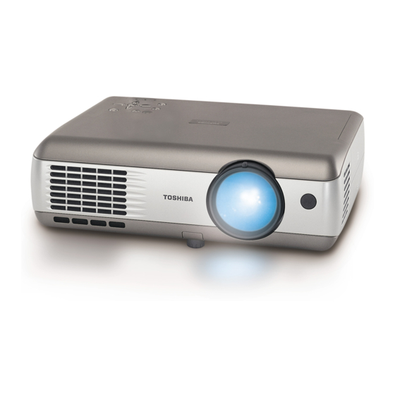
Toshiba TLP-S200 Owner's Manual

Toshiba TLP-S200 Owner's Manual

3lcd data projector (xga / svga / high brightness / with pc card slot & document camera)
Table of Contents

Advertisement

OWNER'S MANUAL
3LCD DATA PROJECTOR
TLP-T700
TLP-T701
TLP-T600
TLP-T601
TLP-T500
TLP-T501
TLP-T400
TLP-T401
TLP-S200
TLP-S201
TLP-T700 / TLP-T600 / TLP-T500 / TLP-T400 / TLP-S200
(XGA / High Brightness / With PC Card Slot)
(XGA / High Brightness / With PC Card Slot & Document Camera)
(XGA / High Brightness)
(XGA / High Brightness / With Document Camera)
(XGA / With PC Card Slot)
(XGA / With PC Card Slot & Document Camera)
(XGA)
(XGA / With Document Camera)
(SVGA)
(SVGA / With Document Camera)

Advertisement

Table of Contents
loading

Summary of Contents for Toshiba TLP-S200

  • Page 1 TLP-T400 TLP-T401 TLP-S200 TLP-S201 TLP-T700 / TLP-T600 / TLP-T500 / TLP-T400 / TLP-S200 (XGA / High Brightness / With PC Card Slot) (XGA / High Brightness / With PC Card Slot & Document Camera) (XGA / High Brightness) (XGA / High Brightness / With Document Camera) (XGA / With PC Card Slot) (XGA / With PC Card Slot &...
  • Page 2: Safety Precautions

    WARNING: Changes or modifications made to this equipment, not expressly approved by Toshiba, or parties authorized by Toshiba, could void the user’s authority to operate USA only the equipment.
  • Page 3 IMPORTANT SAFETY INSTRUCTIONS (Continued) 5. Heat 8. Power-Cord Protection The product should be situated Power-supply cords should be away from heat sources such as routed so that they are not likely to radiators, heat registers, stoves, or be walked on or pinched by items other products (including placed upon or against them, amplifiers) that produce heat.
  • Page 4 IMPORTANT SAFETY INSTRUCTIONS (Continued) 16. Damage Requiring Service 18. Servicing Unplug this product from the wall Do not attempt to service this outlet and refer servicing to product yourself as opening or qualified service personnel under removing covers may expose you the following conditions: to dangerous voltage or other a) When the power-supply cord or...
  • Page 5: Label Locations

    LABEL LOCATIONS CAUTION Label MODEL NO. / SERIAL NO. Label RATING Label MANUFACTURED; WARNING Label 310W SERIAL NO. 1.4A CAUTION Label WARNING Label CAUTION Label (LED) CAUTION Label (LASER) Remote Control Models with Document Camera LASER WARNING CAUTION Label (LASER) Models with Document Camera POWER SUPPLY CORD SELECTION If your line voltage is 220 to 240V, use one of the following types of cable.
  • Page 6: Exemption Clauses

    Toshiba Corporation. • Toshiba bears no responsibility for information being intercepted or leaked due to the use of a wireless LAN, or any damages therefor (models with PC card slot).
  • Page 7: Table Of Contents

    CONTENTS Before Using SAFETY PRECAUTIONS ... 2 IMPORTANT SAFETY INSTRUCTIONS ... 3 LABEL LOCATIONS ... 8 POWER SUPPLY CORD SELECTION ... 9 IMPORTANT PRECAUTIONS ... 9 EXEMPTION CLAUSES ... 11 OTHER CAUTIONS AND INFORMATIONS ... 11 CONTENTS ... 12 Preparations Checking the package contents ...
  • Page 8: Checking The Package Contents

    Checking the package contents Please make sure that the following items are included in the box, along with the main unit. If an item is missing, please contact the store from which you purchased the product immediately. (10) (11) (12) (1) Remote control (8) RGB cable (2) AAA dry-cell batteries for remote...
  • Page 9: Names Of Each Part On The Control Panel And Remote Control

    Names of each part on the control panel and remote control Control panel Remote Control Front Remote control transmitter INPUT ON/STANDBY AUTO KEYSTONE (19) MENU VOL.- AUTO SET VOL. + VOL. - PJ MODE (18) MENU / ENTER R-CLICK (17) INPUT TEMP LAMP AUTO SET FREEZE...
  • Page 10: Names Of The Connection Terminals

    Names of the connection terminals I Removing the connection terminal cover Press on the circle (“O”) while sliding the cover in the direction of the arrow. The cover will come off. MONITOR COMPUTER ( Y,P CONTROL VIDEO AUDIO R - AUDIO - L VIDEO S-VIDEO (1) COMPUTER 2 terminal...
  • Page 11: Placement

    Preparing and using the remote control (Continued) Switching operation modes Operation modes should be switched between projector operation and computer operation. Switching the remote control operation mode. Pressing this button toggles the mode. When this button is lit, the remote control is in [PJ Mode] (Projector operation mode).
  • Page 12: Connection

    Connection Before connection • Read the owner’s manual of the device to be connected to the projector. • Some types of computer cannot be used connected to this projector. Check for an RGB output terminal, supported signal p.68 • Turn off the power of both devices before connection. •...
  • Page 13: Installing The Application

    Operations I How to uninstall Select [Start Menu] → [Settings] → [Control Panel] → [Add/Remove Programs], and remove Toshiba Data Projector from currently installed programs. Turning the power on and off Connecting the power cord Insert the power cord connector into the AC IN socket of the projector.
  • Page 14: Basic Operations

    Turning the power on and off (Continued) Turning the power off Press the ON/STANDBY button. A message appears on the screen, confirming that you wish to shut off the power. This message will disappear after a moment. (This operation is no longer valid after the message disappears.) Press the ON/STANDBY button again.
  • Page 15: Using Handy Features

    Basic operations (Continued) Projector placement angle adjustments The placement angle and the height of the projected image can be adjusted by the foot adjuster. q Lift up the front of the projector until it is at the desired angle, then press the foot adjuster release button.
  • Page 16: Correcting The Keystone Distortion (Keystone)

    Using handy features (Continued) Correcting the keystone distortion (Keystone) p.28 When the foot adjuster is used to change the projection angle, the picture will undergo keystone (trap- ezoidal) distortion. This projector is capable of correcting this keystone distortion. Before correction After correction q Press the AUTO KEYSTONE button.
  • Page 17: Displaying Information

    The following functions are available via wireless communications, when the wireless LAN PC card and dedicated Wireless Utility software are used. Note: Toshiba does not guarantee operation if a wireless LAN PC card other than the one supplied with this product is used. “Yes”: displayed, “No”: not displayed Video 1) Displaying a computer’s screen via the projector...
  • Page 18: Communication Mode

    Using the wireless LAN PC card (Continued) Preparation Mount the supplied wireless LAN PC card into the projector, and select PC card input Referring to “Mounting a PC card,” p.23 mount the supplied wireless LAN PC card, then select PC card input in accordance with “Select input” Projector settings The factory settings can be used as-is.
  • Page 19: Displaying A Jpeg Image Saved On A Computer Via The Projector

    Using the wireless LAN PC card (Continued) Select the screen image you wish the projector to display. Select Desktop The computer screen image is transmitted as-is. Select application window ® Select a running application (e.g. Microsoft PowerPoint ® ), and send that application’s window only.
  • Page 20: Operating The Projector

    Using the wireless LAN PC card (Continued) Select the projector to be transmitted. A list of the MAC addresses of the wireless LAN PC cards p.32 p.59 mounted on the projectors that are available for transmission appears. If projector name has been set up already, it is shown instead of the MAC address.
  • Page 21: Projecting Images Stored In A Memory Pc Card

    Backing up data Toshiba recommend that you back up the data on the memory PC card before use. (Toshiba assume no liability for losses incurred by data lost through the use of this projector.)
  • Page 22 Projecting images stored in a memory PC card (Continued) Indicates that only folders are inside the folder. Indicates that the JPEG or other file is not supported. Indicates that there is no data to be displayed in the folder. Searching for a target file •...
  • Page 23: Using The Document Camera

    Using the document camera Please read this chapter if the model you purchased includes a document camera. Preparation of the document camera 1) Set up arm Status before preparation (When stowed) 3) Rotate arm 4) Extend camera head PRECAUTIONS • Do not jolt or force the camera head or camera arm. Doing so could cause malfunction. •...
  • Page 24: Using The Overlay Function

    Using the document camera (Continued) I Using the overlay function The overlay function can be used to write over computer or video input images. Have a piece of white paper, and a red or blue pen ready. Place the piece of white paper on a flat surface, photograph it with the document camera, and display it on the screen.
  • Page 25: Sending The Camera's Images To A Computer

    Using the document camera (Continued) I Sending the camera’s images to a computer Models equipped with a PC card slot can use a wireless LAN PC card to send images taken with the document camera to a computer in JPEG format, and open them, or save them to disk.
  • Page 26: Storing The Camera Images Into The Memory Card

    Using the document camera (Continued) I Storing the camera images into the memory PC card Models equipped with a PC card slot are able to save image data taken with the document camera onto a memory PC card (sold separately) in JPEG format. Mount a memory PC card into the PC card slot Mounting a PC card will switch to PC card input if Input select mode is set to Auto on the PC card setting menu...
  • Page 27: Using The Menus

    Using the menus You can call up on-screen menus, and conduct a number of adjustments and settings, using the operation buttons p.16 on the control panel (main unit side) and remote control. How to use the menus The menu shown below is only for operation 1.
  • Page 28: The Display Setting Menu

    Using the menu (Continued) The display setting menu Use this menu to set screen display-related items. Description Item Screen size (Full): Display with LCD panel’s resolution Not displayed with (Thru): Display with sampling resolution (for computer input) PC card input or camera input.
  • Page 29: Air Filter Cleaning

    Air filter cleaning The air filter prevents dust and debris from getting inside the projector. Never run the projector with the filter removed. It is recommended that the air filter is cleaned regularly. (A recommended measure is about once for every 50 hours of use.) CAUTION •...
  • Page 30: How To Use The Supplied Software

    Lamp replacement (Continued) Remove the lamp cover. Loosen the screws, then pull up to direction of the arrow with your fingers on the area shown in the figure to remove the lamp cover. Be careful to avoid breaking a nail or otherwise injuring your fingers when doing so.
  • Page 31: How To Use The Jpeg Conversion Tool

    How to use the supplied software (Continued) Configure the projector. [Channel] This item cannot be changed currently. [Encryption] Click on the button to select [Off], [64 bit], or [128 bit]. [Key] This accepts input if Encryption is set to other than Off (input is required). Input a value from the keyboard.
  • Page 32 How to use the supplied software (Continued) G Converting files created with Microsoft ® PowerPoint This process provides presentations without using a computer by converting presentation files created with Microsoft ® PowerPoint a memory PC card, and displaying them in a slide show. •...
  • Page 33: Trouble Indications

    Trouble indications The indicator lights inform you of internal abnormalities. TEMP LAMP No power ⇒ Problem with projector (Off) (Red lit) • Unplug the power cord, and contact your dealer. Lamp went out during use, or won’t come on TEMP LAMP ⇒...
  • Page 34: Specifications

    Before calling service personnel (Continued) If This Happens Check Mouse remote • Are the USB cable and mouse remote control receiver (Models control doesn't equipped with PC card slot) correctly connected? work • Do your computer and OS support USB? •...
  • Page 35: B /P R Signals)

    Specifications (Continued) I List of supported signals (RGB signals) This projector supports the following RGB signals. Note, however, that depending on the computer model, the screen may show flicker or streaking. Please adjust the projector if this happens. (Press the AUTO SET button, and adjust automatically or manually. Refresh rate Resolution Mode...
  • Page 36: Control Terminal

    Specifications (Continued) I CONTROL terminal G Pin assignment Pin No. Signal Name Mini DIN 8 pin connector G Interface format 1 Communication method RS-232C, 9600bps, No Parity, Data Length: 8 bits; Stop Bit Length: 1 bit 2 Communication format STX (02h) Command (3Byte) ETX (03h) Only 1 command valid per communication.

Table of Contents