
Related Manuals for Toshiba TLP-T50M


Summary of Contents for Toshiba TLP-T50M
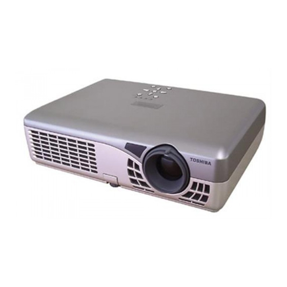
- Page 1 FILE NO. 330-200301 SERVICE MANUAL 3LCD DATA PROJECTOR TLP-T50M TLP-T50 TLP-S30 TLP-T50/TLP-T50M/TLP-S30...
-
Page 2: Safety Precaution
SAFETY PRECAUTION WARNING: Service should not be attempted by anyone unfamiliar with the necessary precautions on this projector. The following are the necessary precautions to be observed before servicing this chassis. 1. An isolation Transformer should be connected in the power line between the projector and the AC Iine before any service is performed on the projector. -
Page 3: Table Of Contents
TABLE OF CONTENTS SAFETY PRECAUTION ......... 0-2 PRODUCT SAFETY NOTICE ......0-2 ULTRAVIOLET DANGER IN SERVICE MODE ..0-2 SECTION 1 PART REPLACEMENT AND ADJUSTMENT PROCEDURES 1. LOCATION OF MAIN PARTS ......1-1 3-10. Power Block ........1-16 2. LOCATION OF PC BOARD ......1-1 3-11. -
Page 4: Safety Precautions
WARNING: Changes or modifications made to this equipment, not expressly approved by The openings should never be consult your product dealer or Toshiba, or parties authorized by Toshiba, could void the user’s authority to operate USA only blocked by placing the product on local power company. - Page 5 IMPORTANT SAFETY INSTRUCTIONS (Continued) 5. Heat 8. Power-Cord Protection 11. Object and Liquid Entry 14. Attachments The product should be situated Power-supply cords should be Never push objects of any kind Do not use attachments not away from heat sources such as routed so that they are not likely to into this product through openings recommended by the product...
- Page 6 IMPORTANT SAFETY INSTRUCTIONS (Continued) 16. Damage Requiring Service 18. Servicing 21. Do not leave thermal-paper documents or easily Unplug this product from the wall Do not attempt to service this outlet and refer servicing to product yourself as opening or deformed items on top of qualified service personnel under removing covers may expose you...
-
Page 7: Power Supply Cord Selection
POWER SUPPLY CORD SELECTION IMPORTANT PRECAUTIONS (Continued) Avoid Volatile Liquid If your line voltage is 220 to 240V, use one of the following types of cable. Do not use volatile liquids, such as an insect spray, near the unit. Do not leave rubber or Plug Plug configuration Plug type... -
Page 11: Part Replacement And Adjustment Procedures
SECTION 1 PART REPLACEMENT AND ADJUSTMENT PROCEDURES 1. LOCATION OF MAIN PARTS LAMP HOUSE Z102: PBS FAN Z101: EXHAUST FAN P200: SPEAKER P850: BALLAST POWER SUPPLY LCD BLOCK P800: MAIN POWER 0000: Z100: INTAKE FAN Z100: INTAKE FAN PROJECTION LENS 2. -
Page 12: Replacement Of Mechanical Parts
CAUTIONS BEFORE SERVICING Electronic parts are susceptible to static electricity and may easily be damaged, so do not forget to take proper grounding treatment as required. Many screws are used inside the unit. To prevent missing, dropping, etc. of the screws, always use a magnetized screwdriver on servicing. -
Page 13: Top Cover
3-2. Top Cover Step Figure Explanation [Front Side] Remove the sheet mask screw (sheet for screw cover). (Pull the notch of the sheet mask screw using tweezers etc, and then removed.) Remove 1 screw (M3 x 6). Screw: type [M-2] [Right Side] Remove 2 screws (M3 x 6). -
Page 14: Main Pc Board
3-3. Main PC Board Step Figure Explanation Disconnect all cables and connectors. Remove 3 screws (M3 x 6). Screw: type [M-2] (a) Remove 1 screw (M3 x 6) in the rear side. Rear side screw: type [M-2] ( b ) ( b ) ( b ) (b) Remove 1 ground screw (M3 x 6). - Page 15 3-3. Main PC Board (Continued) Step Figure Explanation Remove the terminal board cover.
-
Page 16: Optical Engine
3-4. Optical Engine Step Figure Explanation Cable retainer Cable retainer Cable retainer . Remove 1 screw (a) on the lamp housing, and cut the cable retainer. Remove the white cable from the cable retainer. . Remove 1 screw (a) of the cable retainer, and 2 screws (b and c) of lamp housing. -
Page 17: Lcd Panel
3-5. LCD Panel Step Figure Explanation Lamp housing Lamp housing Lamp housing <Removal> Remove 1 screw (M3 x 6) on the lamp housing, and remove the lamp housing. Screw: type [M-1] Remove 2 screws (M2.5 x 8SW). Screw: type [E-1] Sub frame Sub frame Sub frame... -
Page 18: Lcd Panel
3-5. LCD Panel (Continued) Step Figure Explanation Separate the LCD panel, mask and bracket. [Note] Keep the mask because it is used again. The old LCD panel and 4 screws are not used. <Installtion> Prepare a new LCD panel to be replaced. Prepare two pairs of screws and washers ((a) and (b)) for LCD panel installation. -
Page 19: Polarized Plate On The Main Frame
3-6. Polarized Plate on the Main Frame Step Figure Explanation <Removal> Remove 1 screw (2 x 2). Screw: type [E-6] Remove the retainer. Remove the polarized plate. - Page 20 3-6. Polarized Plate on the Main Frame (Continued) Step Figure Explanation <Installation> When installing the polarized plate, the film side must Color marking Color marking Color marking face the LCD panel, and the color marking must be the same color as the LCD panel. Polarizer Polarizer Polarizer...
-
Page 21: Polarized Plate On The Sub Frame
3-7. Polarized Plate on the Sub Frame Step Figure Explanation <Removal> Remove 1 screw (M2 x 2) each of the polarized plates. Screw: type [E-2] Remove the polarized plate. 1-11... - Page 22 3-7. Polarized Plate on the Sub Frame (Continued) Step Figure Explanation <Installation> When installing the polarized plate, the film side must Color marking Color marking Color marking face the LCD panel, and the color marking must be the same color as the LCD panel. Polarizer film Polarizer film Polarizer film...
-
Page 23: Multi-Pbs (Polarizing Beam Splitter)
3-8. MULTI-PBS (Polarizing Beam Splitter) Step Figure Explanation Remove 1 screw (M3 x 6). Screw: type [M-1] Remove 2 screws (M2.5 x 8SW). Screw: type [E-1] After pulling out the fitting spring from the gap between Multi-PBS and frame, remove the Multi-PBS. Lamp Lamp Lamp... -
Page 24: Intake Fan
3-9. Intake Fan Step Figure Explanation Remove filter from bottom plate. Remove 3 screws (3 x 8). Screw: type [M-4] Remove 3 sheets of tape. Tape Tape Tape Remove 2 screws (3 x 14). Tape Tape Tape Tape Tape Tape Screw: type [M-3] The fan block is separated into 3 pieces as shown. - Page 25 3-9. Intake Fan (Continued) Step Figure Explanation Fan piece Fan piece Fan piece The fan block is separated into 3 pieces as shown. Fan cover Fan cover Fan cover 1-15...
-
Page 26: Power Block
3-10. Power Block Step Figure Explanation Remove 1 screw (M3 x 6). Screw: type [M-1] Remove 1 screw (3 x 8). Screw: type [M-4] Remove the power block. Remove 2 screws (a and b) of the fan blocks 1 and 2. Spacer Spacer Spacer... - Page 27 3-10. Power Block (Continued) Step Figure Explanation A. Remove 1 screw (M3 x 6). B. Remove 1 retainer. [Note] . Cut the cable retainer fastening the cable between ballast power supply and power supply block. . Cut the cable retainer fastening the lead wire between ballast power supply and main board.
-
Page 28: Ballast Power Supply
3-11. Ballast Power Supply Step Figure Explanation Disconnect the cable from the ballast power supply. Remove the ballast power supply by releasing it from retainer. 1-18... -
Page 29: Speaker Block
3-12. Speaker Block Step Figure Explanation Remove harness from 2 hooks on the bottom plate. Pull the speaker up to remove. Disconnect the connector. Remove 1 screw (3 x 8). Screw: type [M-4] Remove safety interlock switch PC board. 1-19... -
Page 30: Screws For Mechanical Parts
3-13. Screws for Mechanical Parts Type Form Size Location M3 x 6 Main Board (4), Lamp Power Block (1) Power Block (1), Lamp Housing (1) M3 x 6 Top Cover (7), Main PCB (3), Back terminal board (3) 3 x 14 Intake Fan (4) 3 x 8 Intake Fan (3), Safety Inter Lock Switch Board (1),... -
Page 31: Screws For Optical Engine
3-14. Screws for Optical Engine Type Form Size Location M2.5 x 8SW Main Frame (2), Retaining Lid of MULTI-PBS (2) 2 x 2 Sub Frame (3) M2 x 5 LCD Panel (12) M2.5 x 6.5 LCD Panel (2) Contained in Service kit M2.5 x 6.5 LCD Panel (2) Contained in Service kit... - Page 32 3-15. How to Disconnect FFC/FPC Connector Step Figure Explanation Location number: Main PCB: PJ402 Release 2 retaining tabs. [Note] Retaining tabs stop when released. Do not use excessive force to release tabs. FFC/FPC cable can be disconnected. 1-22...
-
Page 33: Optical Adjustment
(6) Test Pattern Setup 4. OPTICAL ADJUSTMENT Connect a computer with RGB cable, and start 4-1. Preparation the Pattern generating software (SINGO98.exe). < Test Equipments and Test Jigs > . Personal computer (Windows P/C, OS:windows 95/98) . Adjustment software SINGO98.exe . - Page 34 4-2. Adjustment of Convergence (ex. Red panel exchange) Step Figure Explanation TEST PATTERN: Green and Red Cross Hatches (when performing [R] adjustment) Move the panel to back and front, right and left, and adjust the convergence using the service kit. Tighten 4 screws using the wrench in the service kit.
-
Page 35: Troubleshooting
SECTION 2 SERVICING DIAGRAMS 1. TROUBLESHOOTING SYMPTOM CHECK INSPECT RESULT (NG) → Power supply is NG. Flat cable of Power supply Standby voltage (disconnect PJ1) (See page 2-2) (OK) → Check next step. Power is not on (NG) → Main PCB is NG, PJ1(connect PJ1) Standby voltage or any cable connection is NG. -
Page 36: Indicator Combination)
2. LED DISPLAY (Problems Shown on LED Indicator Combination) Status of Indicator Light Error Cord Cause and Trouble Solution TEMP LAMP Standby-power is not on Check the power unit. > There's a problem with (OFF) (OFF) (OFF) (OFF) Check the connector. the power unit or system microcomputer. -
Page 37: Wiring Block Diagram
3. WIRING BLOCK DIAGRAM SAFETY INTERLOCK SPEAKER SWITCH BOARD PJ1101 PJ006 MAIN PC BOARD PJ605 PJ901 PJ354 PJ951 PJ851 PJ352 PJ604 LAMP DRIVER PJ402 EXHAUST PJ355 (PBS FAN) PJ001 PJ353 PJ005 CN105 CN101 CN101 CN202 MAIN POWER CN201 PJ201 UNIT SENSOR PC BOARD INTAKE FAN 1... -
Page 38: Connector Pin Assignment
10 VIDEO8 SIGNAL (7V ± 5V) 4. CONNECTOR PIN ASSIGNMENT 11 VIDEO7 SIGNAL (7V ± 5V) 12 VIDEO6 SIGNAL (7V ± 5V) PJ001 (MAIN) PJ201 (SENSOR) 1 MCU-3V12C-SCL 0-3.3Vp-p 13 VIDEO5 SIGNAL (7V ± 5V) 14 VIDEO4 SIGNAL (7V ± 5V) 2 MCU-3V12C-SDA 0-3.3Vp-p 3 SHS+3.3V... - Page 39 PJ402 (MAIN) CN202 (POWER UNIT (APS-M423)) 1 +3.3V 2 +3.3V 3 +3.3V 4 AGND 5 AGND 6 AGND 7 +6.5V 8 AGND 9 NC 10 -10.5V 11 AGND 12 NC 13 +15.5V 14 +15.5V 15 AGND 16 AGND 17 NC 18 +15.5V 19 AGND 20 NC...
-
Page 40: Exploded Views
SECTION 3 PARTS LIST SAFETY PRECAUTION Replace only with part number specified. The mounting position of replacement is to be identical with originals. The substitute replacement parts which do not have the same safety characteristics as specified in the parts list may cause shock, fire or other hazards. -
Page 41: Accessories
1-2. Accessories PARTS NO. FORM PARTS NO. FORM DESCRIPTION DESCRIPTION Remote Y210 AV Cable Y240 Control Unit Audio Cable for Y105 Computer Battery Audio Cable Y221 Quick Y229 Sheet Y231 Y232 Y265 Carrying Bag Y200 CD ROM Owner's Y201/Y203 Manual Mouse Remote Control Set Power Cord... -
Page 42: Chassis Assembly
1-3. Chassis Assembly A100: TOP COVER SS01: THERMOSTAT SWITCH Z100: INTAKE FA P200: SPEAKER Z100: INTAKE F F AN TERMINAL BOARD COVER B100: BOTTOM CABINET BOTTOM CABI LANP UNIT A231: AIR FILTER A240: LAMP COVER... -
Page 43: Pc Board And Power Unit Assembly
1-4. PC Board and Power Unit Assembly Z101: EXHAUST FAN U001: MAIN PC BOARD Z102: CORD RETAINER PBS FAN U003: SAFTY INTERLOCK (DOOR) SW PC BOARD P850: BALLAST POWER SUPPLY U002: SENSOR PC BOARD P800: MAIN POWER... -
Page 44: Optical Engine Assembly
1-5. Optical Engine Assembly E200: OPTICAL ENGINE ASSEMBLY SUB FRAME POLARIZER (B) POLARIZER (G) POLARIZER (R) MAIN FRAME POLARIZER (G) POLARIZER (B) POLARIZER (R) E201B: E201G: LCD PANEL (B) LCD PANEL (G) E201R: LCD PANEL (R) PROJECTION LENS... -
Page 45: Label
1-6. Label A300: CAUTION Label TOP TAG Sheet WARNING Label A303: CAUTION Label SERIAL NO. Label WARNING Label MODEL NO./ PATING Label... -
Page 46: Parts List
COVER, ASSY LAMP A280 23890986 LENS CAP A300 23541111 SHEET, TOP TAG TLP-T50 A300 23541112 SHEET, TOP TAG TLP-S30 A300 23541119 SHEET, TOP TAG TLP-T50M A303 23555255 LABEL RATING TLP-T50 A303 23555256 LABEL RATING TLP-S30 A303 23555328 LABEL RATING TLP-T50M A350 23555257... - Page 47 Location Part No. Description Model Z101 23125905 FAN, D07A-12PH 01A Z102 23125906 FAN, 06KL-04W-B49 23405207 LENS, 520LENS 23405208 OPTICAL PARTS(MECHA), 520MAIN TLP-T50 23405209 OPTICAL PARTS(MECHA), 520MAIN TLP-S30 23405210 OPTICAL PARTS(MECHA), 520SUB 23405211 POLARIZAR, I-R(520) 23405212 POLARIZAR, I-G(520) 23405213 POLARIZAR, I-B(520) 23405214 POLARIZAR, O-R(520) 23405215...
- Page 48 1-1, SHIBAURA 1- CHOME, MINATO - KU, TOKYO 105 - 8001, JAPAN...
Need help?
Do you have a question about the TLP-T50M and is the answer not in the manual?
Questions and answers