
Related Manuals for ZKTeco SBT1000S Series


Summary of Contents for ZKTeco SBT1000S Series
- Page 1 Swing Barrier Turnstile Installation Guide Applicable Models: SBT1000S Version: 1.2 Date: May. 2018...
-
Page 2: Chapter 1 Overview
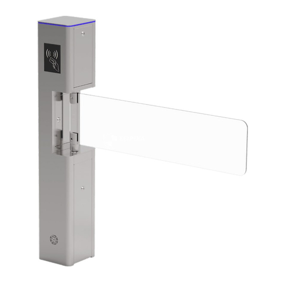
3) In order to avoid the impact on communication, 220V/110V power line (high voltage) and signal line (low voltage) should be separated. The ground wire must be connected. SBT1000S series appearances and sizes as shown in Figure 1-1 Figure 1-1 Chapter 2 Installation 2.1 Before the installation, it is necessary to check the device first:... - Page 3 Figure 2-2 2.3 Chassis installation 1) Verify the accessories on the list and gather tools. 2) Posit the machine on the right place. 3) Drill on the ground according to the positioning tape. 4) Embedding four expansion bolts (M12) into the positioning holes. 5) Remove the access cover, as shown in Figure 2-4A.
-
Page 4: Chapter 3 Wiring Diagram And Menu Instruction
Figure 2-3C Figure 2-3D Chapter 3 Wiring diagram and menu instruction 3.1 Wiring diagram Check circuit according to the following wiring diagram: SBT1000S series Motor Wiring diagram 485A EGND 458B AP-R:IR3 Infrared sensor IR3 on the top Lock2 Encoder Lock1... -
Page 5: Chapter 4 Troubleshooting
3.2 Menu instruction There are 4 keys on the control panel, including "UP", "DOWN", "ENT" and "ESC". Press the ENT button, enter the password input interface, the default password is: UP, UP, DOWN, DOWN, DOWN, DOWN. If any step fails please press the ESC button to get back. 3.3 Modify the menu After enter the menu operation system, press “UP”...
Need help?
Do you have a question about the SBT1000S Series and is the answer not in the manual?
Questions and answers