Advertisement
Advertisement
Table of Contents

Subscribe to Our Youtube Channel
Summary of Contents for King gates ISTBJV01
- Page 1 ROLLS INSTRUCTION MANUAL ISTBJV01...
- Page 3 18 mm...
-
Page 6: Main Features
Before installing the product ascertain that safety conditions are observed according to the law, rules and regulation. Use personal safety devices and locate warning signs on the motorized gate. Unfulfilment of the below listed direction will release the King gates srl from any responsibility for damage caused to people or things. -
Page 7: Typical System
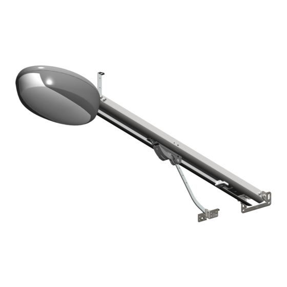
TYPICAL SYSTEM Gear-motor Photocell Flashing-light Key selector Adaptor arm... -
Page 8: Installation
INSTALLATION ASSEMBLING THE “BELT UNIT” To assemble “belt unit”, proceed as follows: - Slide one end of the belt into the transfer pulley (A) and the other end into the motor support (B) following the orientation shown in figures 1 and 2 - Then join the two ends with the plastic joint (C). -
Page 9: Manual Manoeuvre
FIXING THE DOOR TO THE BRACKET Set the automation to manual operation (fig.20), and then drag the carriage to the door. Fix the bracket (Q) to the door making sure the two surfaces mate perfectly (fig.17). Please verify it is firmly fastened, opening and closing the door manually. ADJUSTING THE END OF STROKE With the automation set on manual operation, fully close the door, loosen the catch screw (R) and join the catch itself to the drive carriage. -
Page 10: Electrical Connections
ELECTRICAL CONNECTIONS To get the control unit, open cover and loosening the screw (A). Pass the cables through zone B. Carry out the cabling according to the diagram below. The connections must be made exclusively by qualified personnel when the voltage is off. CONNECTION DIAGRAM PHOTOCELL CONNECTION - “VIKY”... - Page 11 PROGRAMMING THE RADIO REMOTE CONTROLS PROGRAMMING THE CHANNEL FOR ACTIVATING THE AUTOMATION Check that the control units is not set to operate with the dead man's switch (DIPs 2 and 3 must not both be OFF). Press button P2/RAD Power up the control Make a transmission for 2 seconds unit and put DIP 1...
-
Page 12: Program The Travel Limits
PROGRAM THE TRAVEL LIMITS SIMPLIFIED LEARNING PROCEDURE For better adjustment of the obstruction control, it may be necessary (mainly with the trimmer “FOR” set at the maximum or with heavy doors), to intervene during the opening and closing phases (points 7 - 8 - 10) by pressing the activation key of the transmitter or the push button P1/SET on the control unit as soon as the driving carriage comes into contact with the mechanical stop. - Page 13 PROFESSIONAL LEARNING PROCEDURE Using this procedure the installer can determine the instant in which deceleration begins and the back jump type. Press and hold Within 5 seconds, press Put the door in an the programming button the programming button intermediate position. P1/SET for 2 sec.
-
Page 14: Operation Modes
OPERATION MODES TIMED AUTOMATIC CLOSING MODE Put DIP 3 in the ON position and DIP 2 in the OFF position. In this mode, if a command is given via radio or through the “STR” input, the control unit: 1 2 3 4 - gives a steady flash of one second. -
Page 15: Operation Of The Safety Devices
TRIMMER Trimmer “FOR” - Motor speed Use the “FOR” trimmer to adjust the voltage with which the motor is powered during operation, thus adjusting its speed. This is settable between 50% and 100% of the maximum force and can be increased by turning the trimmer clockwise. Thus if the trimmer is set on the minimum then the speed is equal to about 50%, if adjusted in an intermediate position it is equal to 75%, while at the maximum the speed will be the largest obtainable. -
Page 16: Courtesy Light
FLASHING LIGHT The control unit has two output terminals (LAMP) to command a low voltage flashing light (24Vdc). The light start flashing 1 second before each manoeuvre. If the DIP 4 is in the OFF position the power supply to the flashing light is continuous. Therefore the terminals must be connected to a flashing light with a built-in oscillating circuit. -
Page 17: Maintenance
MAINTENANCE The system does not require any specific maintenance. However, what is required is a periodic inspection of the state of the fastenings, wear on the moving parts (pulleys, carriages...) and the belt tension. LED Signal Battery charger Motor and connection encoder connection... - Page 18 MADE IN ITALY King Gates S.r.l. Via A. Malignani, 42 - 33077 Sacile (PN) ITALY Tel. +39 0434 737082 - Fax +39 0434 785351 e-mail: info@king-gates.com web: www.king-gates.com...


Need help?
Do you have a question about the ISTBJV01 and is the answer not in the manual?
Questions and answers