Advertisement
Quick Links
63091-111
Assembly mAnuAl
A
B
C
D
E
F
G
importAnt note: when a spiral slide is mounted directly to your set, be sure to mount a trapeze in
the swing position closest to the gym. Any other accessories could cause a conflict of play.
Adapter components
J 1 31766-102
Deck Slat 5/4 x 6 x 19"
K 1 32594-102
Bottom Side Supp. 2 x 4 x 56-1/2"
L 2 32596-102
Platform Board 5/4 x 4 x 19"
M 3 32599-102
Short Wall Slat 5/4 x 6 x 25"
N 1 32606-102
Top Support 2 x 4 x 28-3/4"
O 1 32608-102
Wall Support 2 x 6 x 56-1/2"
P 1 35417-102
Left Ladder Rail 2 x 4 x 59"
Q 1 35418-102
Right Ladder Rail 2 x 4 x 59"
R 1 35419-102
Left Platform Side 2 x 4 x 11-3/4"
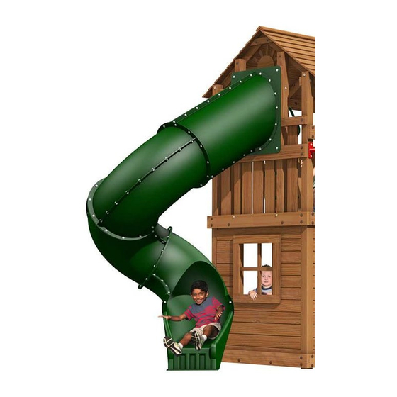
Direct connect ADApter
for spirAl & swoosh sliDes
Direct Adapter: 63091-111
spiral slide: 8400-202
or
swoosh slide: 15140-400
S 1 35420-102
T 2 35421-102
U 2 35422-102
V 2 32607-102
W 2 35423-102
X 2 35425-102
Y 2 14179-400
Z 2 14198-400
A A 4 15139-400
1 50567-700
Right Platform Side 2 x 4 x 11-3/4"
Side Support 4 x 4 x 66"
Side Filler 2 x 4 x 17-1/2"
Top Wall Support 2 x 4 x 17-1/8"
Bottom Side Filler 2 x 4 x 7-1/2"
Long Slat 5/4 x 6 x 37-1/2"
Deluxe Hand Grip
Steel Rung 1-3/8" Dia. x 20-3/4"
Rung Collar, Green 1-3/8" Dia. x 7/8"
Hardware, Direct Connect
N
T
U
W
Y
L
J
S
V
M
R
O
AA
Z
Q
P
X
K
Advertisement

Subscribe to Our Youtube Channel
Related Manuals for Creative Playthings 63091-111


Summary of Contents for Creative Playthings 63091-111
- Page 1 Direct connect ADApter 63091-111 for spirAl & swoosh sliDes Assembly mAnuAl Direct Adapter: 63091-111 spiral slide: 8400-202 swoosh slide: 15140-400 importAnt note: when a spiral slide is mounted directly to your set, be sure to mount a trapeze in the swing position closest to the gym. Any other accessories could cause a conflict of play.
-
Page 2: Slide Components
Assembly instructions slide components G-(1) Run-off Section P/N 15064-1479-Green E-(3) Bottom Elbow A-(1) Mounting Plate C-(1) Right Entrance P/N 15064-1476-Green P/N 15064-1480-Green P/N 15064-1474-Green H-(1) Lower Slide Support Bracket P/N 15064-1120 B-(1) Left Entrance D-(2) Top Elbow F-(1) Exit Section i-(2) Spiral Slide Anchor Nail P/N 15064-1475-Green P/N 15064-1477-Green P/N 15064-1478-Green P/N 12100-848 fasteners lock washer 5/16" lock nut 5/16" 5/16 x 1-1/2" lag screw flat washer 1/4" flat washer 5/16" 5/16 x 2-1/2"... - Page 3 Assembly instructions tools & supplies needed • Electric Drill • C-Wrench or 7/16" Ratcheting Box Wrench • 3/8" & 3/16" Dia. Drill Bits • Level • Phillips Driver Bit T o Alter 9ft Beam: • Tape Measure • Saw • Pencil • Brown Stain • Socket Wrenches with Extension • 1" Dia. Drill Bit • 8 Foot Step Ladder usage & safety information This Direct Connect Adapter is designed to mount on the gable end of the Williamsburg or Lexington gym with a wood roof. The Spiral Slide and the Swoosh Slide add to the safe play zone requirements for the gym. Make sure the slides do not conflict with other play accessories. the slide must not exit in front of or behind swings. Never mount a 9 Foot Swing Beam to the same end of the gym as the Spiral Slide Direct Connect. To mount a 9 Foot Swing Beam adjacent to the Swoosh Slide Direct Connect see the instructions starting at the bottom of page 10 of this document.
-
Page 4: Step 3 - Install Adapter
Assembly instructions step 3 — install Adapter note: it is recommended 4" Hex Bolt that two people perform Carefully raise the Adapter up to the gym tower platform, this step. lean it against the Roof Rafters and make sure the Wall Support (O) is flush with the Corner Posts, as shown. Use a level to make sure the Wall Support is level and the Side Supports are plumb. At the top of the Adapter, mark the position of the countersunk holes onto the Roof Rafters and drill two 3/8" diameter holes 4" Hex Bolt through the Rafters. Fasten the Adapter to the Rafters using two 5/16 x 4" Hex Bolt Assemblies. - Page 5 Assembly instructions step 6 — Assemble ladder 2-1/2" Self- drilling Screws Fit a Rung Collar (AA) onto each end of both Steel Rungs (Z). Fit the Rung assemblies into the holes in the Left Ladder Rail (P) and the Right Ladder Rail (Q). Set the assembly flat on a solid surface. Make sure that the rungs are completely inserted with the ends of the rungs snug against the bottom of the holes. Use #10 x 2-1/2" Self-Drilling Screws, through the holes provided, to fasten the rungs in place. (The Self-Drilling Screws have a drill-bit tip. Point the screw toward the center of rung diameter and press firmly. Do not sink the head of the screw beyond flush with the surface of the wood.) step 7 — install ladder Fasten the Ladder to the Side Supports using two 5/16 x 4"...
-
Page 6: Step 10 - Hand Grips
Assembly instructions step 9 — platform boards Fasten one Platform Board (L) to the Wall Support and Platform Sides using four #8 x 1-5/8" Screws. Align the edge of the Platform Board to the outer edge of the Wall Support. 1-5/8" Screws Fasten the Deck Slat (J) and the remaining Platform Board to the Platform Sides using #8 x 1-5/8" Screws each. The Boards should be tight against each other. No Gap Align these edges step 10 — hand Grips Drill two 3/16" diameter pilot holes 1-1/2" deep into each Ladder Rail as shown. One hole at 14-1/2" from the top of each Rail and the other at 23-1/2" from the top of each Rail. - Page 7 Assembly instructions spiral slide Assembly step 1 — slide entrance Assembly it is important that the coated lag screws provided in the Adapter box be used instead of the lag screws provided in the spiral slide box. Locate one Mounting Plate (A), one Left Entrance (B) and Right Entrance (C). Assemble the Left Entrance Section to the Right Entrance Section using fourteen 5/16 x 3/4" Hex Bolts, twenty-eight 5/16" Flat Washers and fourteen 5/16"...
- Page 8 Assembly instructions step 4 — 1st elbow section Position the first Elbow Section directly under the Entrance Section and rotate two holes off center clockwise. NOTE: There are male and female flanges on all of the sections. Make Entrance sure they match properly. Section Attach the two sections together using twelve 5/16 x 3/4" Hex Bolts, twenty-four 5/16" Flat Washers and twelve 5/16" Lock Nuts as shown in...
- Page 9 Assembly instructions step 8 — bottom slide support Locate the Bottom Slide Support (K), and align with the bottom of the gym where the Direct Adapter for Spiral & Swoosh Slides is installed. Measure approximately 26" from the ground to the top edge of the Bottom Slide Support. Make sure the ends of the Bottom Slide Support are flush with the Corner Posts. Mark the position of the countersunk holes onto the two Corner Posts. Drill a 3/8" hole through...
- Page 10 Assembly instructions step 10 — Anchoring run-off section Anchor Nail Drill two 5/16" holes through each side of the lower flange on 5/16 x 12" the Run-off Section. Hammer the two Anchor Nails into the ground to anchor the front of the Spiral Slide. NOTE: The Anchor Nails will hold better if they are driven in at a slight angle as shown in the illustration. Ground Level Anchor Nail 5/16 x 12" step 11 — hole caps: Make a final check and make sure that all the bolts and screws have been tightened. Locate the 1" Hole Caps in the hardware bag. install Hole Caps into all the counter-bored holes to cover and protect the hardware.
- Page 11 Assembly instructions 1" dia. counter-bore 1/2" Determine side for deep and 3/8" dia. thru. drill counter-bore before drilling. 91-1/2" Gym Brace step 2 — cut and Drill the Gym brace Use a saw to cut the Gym Brace to 91-1/2". Be careful to cut off the square-cut end. Place the off-cut piece even with the cut end of the board and mark the hole positions on the Gym Brace. See the illustration above. Hold the Gym Brace in place to determine the side where a counter-bore is needed. On the side requiring a counter-bore, drill 1" diameter holes 1/2" deep at the marks. At the center of the 1" holes, drill 3/8" diameter holes completely through board. step 3 — finish beam Assembly Use the instructions included with the Swing Beam to complete the installation using the altered parts DiRECT ADAPTER FOR SPiRAL & SWOOSH SLiDES page 11 © Copyright 2017, Creative Playthings, printed in U.S.A.
Need help?
Do you have a question about the 63091-111 and is the answer not in the manual?
Questions and answers