
Related Manuals for Mitsubishi Electric FR-LU08


Summary of Contents for Mitsubishi Electric FR-LU08
- Page 1 INVERTER Option unit FR-LU08 FR-LU08-01 INSTRUCTION MANUAL PRE-OPERATION INSTRUCTIONS LCD Operation Panel FUNCTION AND BASIC OPERATION MENU CHECK FIRST WHEN YOU HAVE TROUBLE SPECIFICATIONS...
- Page 2 Thank you for choosing this Mitsubishi Electric inverter option unit. This Instruction Manual provides handling information and precautions for use of this product. Incorrect handling might cause an unexpected fault. Before using this product, always read this Instruction Manual carefully to use this product correctly.
- Page 3 The surrounding air temperature must be between -10 to +50°C (non-freezing). Otherwise the inverter may be damaged. The surrounding humidity must be 90% RH or less (non-condensing) for the FR-LU08, and 95% RH or less (non-condensing) for the FR-LU08-01. Otherwise the inverter may be damaged.
- Page 4 The items enclosed with the FR-LU08-01 such as the Instruction Manual are not rated with the IPX5 waterproof or IP5X dustproof ratings. Although the FR-LU08-01 (except for the connector) is rated with the IPX5 waterproof and IP5X dustproof ratings, it is not intended for use in water.
-
Page 5: Table Of Contents
─ CONTENTS ─ 1 PRE-OPERATION INSTRUCTIONS Unpacking and checking the product..........................7 1.1.1 SERIAL number check................................7 Major differences between the FR-LU08 and FR-LU08-01 ...................9 Appearance and parts name............................10 Installation and removal..............................12 1.4.1 Installing the operation panel on the inverter ........................12 1.4.2... - Page 6 2.5.4 Precautions for writing the set value ........................... 29 2.5.5 Displaying parameter descriptions (parameter information) ....................29 3 MENU Quick menu ..................................30 3.1.1 Easy setup wizard ................................30 3.1.2 Parameter list by application ............................... 31 3.1.3 Simple setup list .................................. 32 Function menu ................................33 3.2.1 Parameter clear ..................................
-
Page 7: Pre-Operation Instructions
PRE-OPERATION INSTRUCTIONS Unpacking and checking the product Take the operation panel out of the package, and confirm that the product is as you ordered and intact. The FR-LU08(-01) is compatible with the 800 series inverters. 1.1.1 SERIAL number check Check the serial number of the inverter to see if the functions below are supported. - Page 8 Rating plate example Symbol Year Month Control number SERIAL SERIAL number The SERIAL consists of one symbol, two characters indicating the Country production year and month, and six characters indicating the of origin control number. The last digit of the production year is indicated as the Year, and the Month is indicated by 1 to 9, X (October), Y (November), or Z (December).
-
Page 9: Major Differences Between The Fr-Lu08 And Fr-Lu08-01
Major differences between the FR-LU08 and FR-LU08-01 Item FR-LU08 FR-LU08-01 Applicable model Standard model / Separated converter type IP55 compatible model Protective structure IP40 (except for the PU connector) IP55 (except for the PU connector) Outline dimension (WHD [mm]) 7278.517 809619... -
Page 10: Appearance And Parts Name
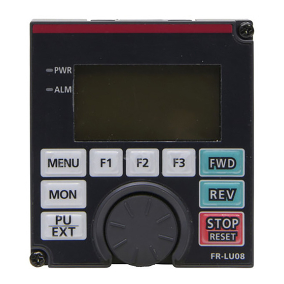
Appearance and parts name Front view Rear view (j) (k) (l) *1 In the FR-LU08-01, this appears as Symbol Name Description Power lamp ON when the power is turned ON. Alarm lamp ON when an inverter alarm occurs. Shows the frequency, parameter number, etc. - Page 11 • Do not operate the keys with sharp tools. • Do not press the LCD part. • Do not peel off the waterproof seal affixed to the FR-LU08-01. If the seal is peeled off, the FR-LU08-01 does not conform to IP55.
-
Page 12: Installation And Removal
Instruction Manual of the inverter.) (2) Align the connector of the FR-LU08(-01) with the PU connector of the inverter, and insert the operation panel. After confirming that the operation panel is fit securely, tighten the screws. For the FR-LU08-01, tighten the screws in a diagonal order. - Page 13 • Removal (1) Loosen the screws on the FR-LU08(-01). (These screws cannot be removed.) (2) Push the upper part of the FR-LU08(-01), and pull out the operation panel to remove. Loosen Loosen Loosen Loosen FR-LU08 FR-LU08 FR-LU08-01 FR-LU08-01 PRE-OPERATION INSTRUCTIONS...
-
Page 14: Connecting The Operation Panel Using A Connection Cable (Fr-Cb2)
Operation panel connection connector (FR-ADP) (option) • Removal Hold down the clip at the cable end and gently pull the connector. NOTE • The IP55 compatible inverter model does not conform to IP55 when the FR-LU08-01 is removed. PRE-OPERATION INSTRUCTIONS... -
Page 15: Installation Of A Backup Battery
Installation of a backup battery With a battery (CR1216), time counting of the FR-LU08(-01) continues even when the main power of the inverter is turned OFF (real time clock function). For the details of the real time clock function, refer to... -
Page 16: Initial Setting
Initial setting 1.5.1 Language selection At first power ON, the Language selection screen appears after the Display Language Language corporation logo of MITSUBISHI ELECTRIC. English Turkish Please Select Language Japanese Polish Turn to select the language, and push to set. English German... -
Page 17: Function And Basic Operation
FUNCTION AND BASIC OPERATION Monitor function 2.1.1 Outline of the Main monitor indicator Output frequency 1 2 : 3 4 ▲ T U N E U S B - A P . R U N 0. 00 ▼ STOP PREV NEXT Symbol Name... - Page 18 Symbol Name Description Displays the operating status of the inverter. [STOP]: During stop [FWD]: During forward rotation Operating status [REV]: During reverse rotation [JOGf]: During JOG forward rotation [JOGr]: During JOG reverse rotation [ALARM]: At fault occurrence Displays time. With a battery installed, the clock keeps working even if the inverter power is turned Clock OFF.
- Page 19 Scroll Displayed when any data can be scrolled by turning For the FR-LU08-01, AUTO will be displayed instead of EXT, and HAND will be displayed instead of PU in the description of the operation mode indicator. Operation mode indicator...
-
Page 20: Using The Real Time Clock Function
(real time clock function). For how to install the backup battery, refer to page • When the battery is installed in the FR-LU08(-01), its time is written to the inverter at power-ON (except the first power-ON after the battery is installed). -
Page 21: Changing The Main Monitor Screen
2.1.4 Changing the Main monitor screen When Pr.52 Operation panel main monitor selection is set to "0", 6 types of the monitor screen are displayed in order by pressing (NEXT) (PREV) Turn ON the power, or press When the first monitor screen When the second monitor screen When the third monitor screen is set as the first priority monitor... -
Page 22: Changing The Main Monitor Item From The Function Menu
2.1.5 Changing the main monitor item from the Function menu The monitor list is displayed when the Monitor selection in the Function menu is selected. When a monitor item is set from the monitor list, the new monitor item is registered and displayed in the fourth monitor screen. (For the Function menu, refer to page 33.) -
Page 23: Frequency Setting
Frequency setting The frequency applied in the PU operation mode or external/PU combined operation mode (Pr.79="3") can be set. To set the frequency, switch the monitor display from the Main monitor screen to the Frequency setting screen, turn input a frequency setting value, and press to confirm the setting. -
Page 24: Direct Setting
Direct setting When setting Pr.1000 Direct setting selection, it is possible to switch from the Main monitor screen to the set point setting screen for PID action using . On each setting screen, turn to input a setting value, and press to confirm the (SET) setting. -
Page 25: Fault History Indicator
Fault history indicator Press while the fault history is displayed to display the details of the fault. Latest fault 1 2 : 3 4 OC During Dec 2014/02/04 10:00 The details of the past eight faults can be checked by pressing Frequency 60.00Hz ▼... -
Page 26: Setting And Changing The Parameter Values
Setting and changing the parameter values For the details on the parameters, refer to the Instruction Manual of the inverter. 2.5.1 Specifying the parameter number to change the set value Example: To change the Pr.8 Deceleration time setting from 5 s to 180 s Turn to set the value to [180.0], and press . -
Page 27: Selecting The Parameter From The Function Group Menu To Change The Set Value
2.5.2 Selecting the parameter from the Function group menu to change the set value Example: To change the F011 Deceleration time setting from 5 s to 180 s Turn to move the cursor to [11 Dec. time], and press Display the Quick menu and press . -
Page 28: Selecting The Parameter From Function Menu To Change The Set Value
2.5.3 Selecting the parameter from Function menu to change the set value Example: To change the Pr.8 Deceleration time setting from 5 s (initial value) to 180 s Turn to move the cursor to [8 Dec. time], and press Display the Function menu, turn to move the cursor to . -
Page 29: Precautions For Writing The Set Value
NOTE • If the parameter setting has been changed from the initial value, the set value can be changed from [Set parameter list]. Turn to move the cursor to the target parameter, and press to change the set value. (SET) 2.5.4 Precautions for writing the set value •... -
Page 30: Menu
MENU Quick menu The parameters can be set by any one of the following methods. Item Description Refer to page Easy setup wizard Initial setting can be completed with facility by following the wizard guide. Parameter list by application [Pr. list for App.] The parameters related to each application of the inverter can be set. -
Page 31: Parameter List By Application
Please choose the Please choose the Please choose the Please input the kind of applied kind of induction control method. number of motor motor. motor. poles. Induction motor SF-JR under 1.5kW V/F control STOP STOP STOP STOP BACK S E T NEXT N E X T BACK... -
Page 32: Simple Setup List
3.1.3 Simple setup list Frequently-used functions (parameters) can be set. Item Item Control method selection Induction motor Auto tuning Motor type Auto tuning setting Magnet motor Minimum frequency Current High speed maximum Motor setting Base frequency voltage frequency Voltage Rated motor voltage Acceleration time Base frequency Deceleration time... -
Page 33: Function Menu
Function menu Various functions can be executed. Refer to Function menu Item page Displays the monitor item list. Monitor item selected from the list can be set and changed on the Monitor selection Main monitor screen. Parameter list Displays [Set parameter list] and [Initial value list]. Set values can be changed from each list. Parameter clear Displays the parameter clear menu. -
Page 34: Parameter Clear
3.2.1 Parameter clear "Parameter clear" and "All parameter clear" can be executed. Set the PU operation mode before execution. • Parameter clear ... The settings of parameters except for calibration parameters and terminal function selection parameters are initialized. • All parameter clear ... The settings of all the parameters, including calibration parameters and terminal function selection parameters, are initialized. -
Page 35: Parameter Copy
FR-LU08(-01). The stored parameter settings can be copied to other inverters of same series. • To read the parameter settings of the inverter and store them to the FR-LU08(-01) A name (up to 9 letters) can be entered for the selected area. - Page 36 • To write the parameter settings stored in the FR-LU08(-01) to an inverter Connect the FR-LU08(-01) to the target inverter. Press to reset the 2 : Write VFD ABCDEFGHI (RESET) Writing is completed inverter. Display the Function menu, turn to move the cursor to...
-
Page 37: Option Installation Monitor
(2) Verifying the parameters The copied parameter settings stored in the FR-LU08(-01) and those in an inverter can be verified. If a verification error occurs, Copy the parameter settings of the source inverter to the FR- the verification is stopped and... -
Page 38: Usb Memory
• [PLC] on the monitor display indicates the programmable controller. (1) Copying parameter settings to a USB memory device • To copy parameter settings as a new file (numbered) A confirmation screen appears Connect the FR-LU08(-01) and a USB memory device to the for execution. AutoNumberedNewFile source inverter. - Page 39 • To copy parameter settings to an existing file Connect the FR-LU08(-01) and a USB memory device to the Turn to move the cursor USB Pr. Copy: CP001 source inverter. to [1: Copy INV to USB], and 1 : Copy INV to USB...
- Page 40 (2) Writing the parameter settings stored on a USB memory device to an inverter Turn to move the cursor Connect the FR-LU08(-01) and a USB memory device to the USB Pr. Copy: CP001 target inverter. to [2: Write USB to INV], and...
- Page 41 (Refer to page 38.) 1 : Copy INV to USB 2 : Write USB to INV to [3: Verify], and press Connect the FR-LU08(-01) and a USB memory device to the (SET) 3 : Verify target inverter. STOP BACK...
- Page 42 (4) Copying a project of the PLC function to a USB memory device A confirmation screen appears Connect the FR-LU08(-01) and a USB memory device to the for execution. PLC Prjct Copy: PRG01 source inverter. 1 : Copy INV to USB...
- Page 43 (5) Writing a project of the PLC function stored on a USB memory device to an inverter A confirmation screen appears Connect the FR-LU08(-01) and a USB memory device to the for execution. PLC Prjct Copy: PRG01 target inverter. 2 : Write USB to INV...
- Page 44 (Refer to page 43.) 1 : Copy INV to USB 2 : Write USB to INV to [3: Verify], and press Connect the FR-LU08(-01) and a USB memory device to the (SET) 3 : Verify target inverter. STOP BACK S E T...
-
Page 45: Check First When You Have Trouble
CHECK FIRST WHEN YOU HAVE TROUBLE Troubleshooting If a fault occurs and the product fails to operate properly, locate the cause of the fault and take proper corrective action by referring to the troubleshooting table below. Contact your local sales representative if the corresponding information is not found in the table, the inverter has problem, or the component parts are damaged. -
Page 46: Specifications
Temperature applicable for a short time, such as in transit The FR-LU08-01 is rated IP55 only when it is installed on the inverter. NOTE • Do not expose the LCD to direct sunlight. • During transportation, avoid applying load to the LCD. -
Page 47: Outline And Enclosure Cut Dimensions
(Unit : mm) length of the two connectors will be different if other (3rd party) operation panel connection cables are used. FR-LU08-01 80±0.5 68±0.5 -0.5 5±0.3 NOTE • The FR-LU08-01 cannot be installed on enclosure surfaces. (Unit : mm) SPECIFICATIONS... -
Page 48: Appendix
Appendix Appendix 1 Disposing of equipment in EU countries • The symbol shown below, which is printed on products for EU countries, means that electronic equipment at the end of its life should be disposed of separately from household waste. •... -
Page 49: Appendix 2 Restricted Use Of Hazardous Substances In Electronic And Electrical Products
Appendix 2 Restricted Use of Hazardous Substances in Electronic and Electrical Products The mark of restricted use of hazardous substances in electronic and electrical products is applied to the product as follows based on the “Management Methods for the Restriction of the Use of Hazardous Substances in Electrical and Electronic Products”... - Page 50 MEMO IB(NA)-0600539ENG-F...
- Page 51 *The manual number is given on the bottom left of the back cover. Revision date *Manual number Revision Jun. 2014 IB(NA)-0600539ENG-A First edition Addition Dec. 2014 IB(NA)-0600539ENG-B • FR-LU08-01 Addition May 2015 IB(NA)-0600539ENG-C • Easy setup wizard, Parameter list by application, Extended direct setting Modification Oct. 2015 IB(NA)-0600539ENG-D • Language selection Addition Jun.
- Page 52 FR-LU08 Instruction Manual Supplement Please make a correction to the following error in this manual. 3.2.3 Terminal assignment (Incorrect) Displays the signals assigned to the I/O terminals of the control circuit and the ON/OFF status of the signals. The terminal status of the plug-in option can be checked if a plug-in option FR-A8AX or FR-A8AY is installed.
- Page 53 INVERTER HEAD OFFICE: TOKYO BUILDING 2-7-3, MARUNOUCHI, CHIYODA-KU, TOKYO 100-8310, JAPAN IB(NA)-0600539ENG-F(1811) MEE Printed in Japan Specifications subject to change without notice.
Need help?
Do you have a question about the FR-LU08 and is the answer not in the manual?
Questions and answers