
Related Manuals for Mitsubishi Electric FR-LU08


Summary of Contents for Mitsubishi Electric FR-LU08
-
Page 1: Instruction Manual
INVERTER Option unit FR-LU08 INSTRUCTION MANUAL PRE-OPERATION INSTRUCTIONS LCD Operation Panel FUNCTION AND BASIC OPERATION MENU CHECK FIRST WHEN YOU HAVE A TROUBLE SPECIFICATIONS... -
Page 2: Safety Instructions
Thank you for choosing this Mitsubishi inverter option unit. This Instruction Manual provides handling information and precautions for use of this product. Incorrect handling might cause an unexpected fault. Before using this product, always read this Instruction Manual carefully to use this product correctly. Please forward this Instruction Manual to the end user. - Page 3 Caution Transportation and mounting The mounting orientation must be correct. The surrounding air temperature must be between -10 to +50°C (non-freezing). Otherwise the inverter may be damaged. The surrounding humidity must be 90%RH or less (non-condensing). Otherwise the inverter may be damaged. ...
-
Page 4: Table Of Contents
─ CONTENTS ─ 1 PRE-OPERATION INSTRUCTIONS Unpacking and checking the product..........................5 Appearance and parts name............................5 Installation and removal..............................7 1.3.1 Installing the operation panel to the inverter ......................... 7 1.3.2 Connecting the operation panel using a connection cable (FR-CB2) ................... 9 1.3.3 Installation of a backup battery ............................ - Page 5 3 MENU Quick menu ..................................23 Function menu ................................24 3.2.1 Parameter clear (Pr.Clear) ..............................25 3.2.2 Inverter reset (INV. reset) ..............................25 3.2.3 Terminal assignment (Selectop) ............................25 3.2.4 Parameter copy (PRCpy set) .............................. 26 3.2.5 Option connection status monitor (Option Instl Mntr)......................28 3.2.6 USB memory device (USB Memory Device)........................
-
Page 6: Pre-Operation Instructions
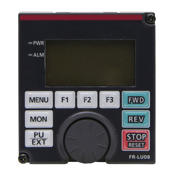
PRE-OPERATION INSTRUCTIONS Unpacking and checking the product Take the operation panel out of the package, and confirm that the product is as you ordered and intact. This product is compatible with the FR-A800 series. Appearance and parts name Front view Rear view (j) (k) (l) Symbol... - Page 7 Symbol Name Description Used to stop operation commands. STOP/RESET key Used to reset the inverter when the protective function is activated. The setting dial is used to change the frequency and parameter settings. Setting dial Pressing the dial shows details of the faults history mode. PU/EXT key Switches between the PU mode, the PUJOG mode, and the External operation mode.
-
Page 8: Installation And Removal
Manual of the inverter.) (2) Align the connector of the FR-LU08 with the PU connector of the inverter, and insert the operation panel. After confirming that the operation panel is fit securely, tighten the screws. (Tightening torque: 0.40 to 0.45 N·m) - Page 9 • Removal (1) Loosen the two screws on the FR-LU08. (These screws cannot be removed.) (2) Push the upper part of the FR-LU08, and pull out the operation panel to remove. Loosen Loosen PRE-OPERATION INSTRUCTIONS...
-
Page 10: Connecting The Operation Panel Using A Connection Cable (Fr-Cb2)
Connecting the operation panel using a connection cable (FR-CB2) • Installation To connect the operation panel (FR-LU08), an optional operation panel connection connector (FR-ADP) is required. (1) Remove the operation panel (FR-DU08) from the inverter. (For the removal of the operation panel, refer to the Instruction Manual of the inverter.) -
Page 11: Installation Of A Backup Battery
Installation of a backup battery With a battery (CR1216), the FR-LU08 time count continues even if the main power of the inverter is turned OFF (real time clock function). For the details of the real time clock function, refer to... -
Page 12: Items To Be Checked First
Items to be checked first 1.4.1 Language selection At first power ON, the language selection screen appears after the corporation Language Selection logo of MITSUBISHI. Please Select Language Turn to select the language, and push to set. English (SET) Japanese The interface language can be changed from the quick menu. -
Page 13: Function And Basic Operation
FUNCTION AND BASIC OPERATION Monitor function 2.1.1 Outline of the monitor indicator Hz Out 1 2 : 3 4 ▲ T U N E U S B - A P . R U N 0. 00 ▼ STOP PREV NEXT Symbol Name Description... - Page 14 Symbol Name Description Displays the operating status of the inverter. STOP: During stop FWD: During forward rotation Operating status indicator REV: During reverse rotation JOGf: During JOG forward rotation JOGr: During JOG reverse rotation ALARM: At fault occurrence Displays time. With a battery installed, the clock keeps working even if the main circuit power Clock indicator supply is turned OFF.
-
Page 15: Using The Real Time Clock Function
For how to install the backup battery, refer to page • When the battery is installed in the FR-LU08, its time is written to the inverter at power-ON (except the first power-ON after the battery is installed). • When the battery is not installed, the FR-LU08 reads the time from the inverter and starts counting of the clock. -
Page 16: Switching The Monitor Data Or The Menu
2.1.3 Switching the monitor data or the menu Pressing switches the monitor data or the menu. Turn ON the power, or press Quick menu Hz Out Function 1 2 : 3 4 Motor setting MONITOR Auto tuning Pr. List 0.00 Min. -
Page 17: Switching The Main Monitor Data
2.1.4 Switching the main monitor data When Pr.52 Operation panel main monitor selection is set to "0", by pressing 6 types of monitor data are (NEXT) (PREV) displayed in order. Turn ON the power, or press When the output frequency When the output current When the output voltage is the first monitor data... -
Page 18: Switching The Main Monitor Data Using The Function Menu
2.1.5 Switching the main monitor data using the function menu The monitor list is displayed when the monitor selection in the function menu is selected. If monitor data is switched from the monitor list, the new monitor data is registered and displayed in the fourth monitor. (For the function menu, refer to page 24.) -
Page 19: Frequency Setting
Frequency setting The frequency applied in the PU operation mode or external/PU combined operation mode Freq Set (Pr.79="3") can be set. Current 60.00Hz While the main monitor data is displayed, turn to input a frequency setting value and press Preset 60.00Hz STOP to confirm the setting. -
Page 20: Setting And Changing The Parameter Values
Setting and changing the parameter values For details on the parameters, refer to the Instruction Manual of the inverter. 2.4.1 Specifying the parameter number to change the set value Example: To change the Pr.8 Deceleration time setting from 5 s to 180 s Turn to set the value to 180.0, and press . -
Page 21: Selecting The Parameter From Functional List To Change The Set Value
2.4.2 Selecting the parameter from functional list to change the set value Example: To change the F011 Deceleration time setting from 5 s to 180 s Turn to move the cursor to [11 Dec. T1], and press Display the quick menu and press . -
Page 22: Selecting The Parameter From Function Menu To Change The Set Value
2.4.3 Selecting the parameter from function menu to change the set value Example: To change the Pr.8 Deceleration time setting from 5 s (initial value) to 180 s Turn to move the cursor to [8 Dec. T1], and press Display the function menu, turn to move the cursor to the (SET) The present set value is displayed. -
Page 23: Precautions For Writing The Set Value
NOTE • If the parameter setting has been changed from the initial value, the set value can be changed using the change list. Turn to move the cursor to the target parameter, and press to change the set value. (SET) 2.4.4 Precautions for writing the set value •... -
Page 24: Menu
MENU Quick menu Frequently-used functions (parameters) can be set. For details on the parameters, refer to the Instruction Manual of the inverter. Quick menu Item Parameter to be set Induction motor Select the motor type and capacity. Motor type Magnet motor Select the motor type and capacity. -
Page 25: Function Menu
• Even if the PU display language has been changed using the quick menu, the Pr.145 PU display language selection setting is not changed. In addition, changing the Pr.145 setting does not affect the language of the FR-LU08. Function menu Various functions can be executed. -
Page 26: Parameter Clear (Pr.clear)
3.2.1 Parameter clear (Pr.Clear) "Parameter clear" and "all parameter clear" can be executed. Set the PU operation mode before execution. • Parameter clear ... The settings of parameters except for calibration parameters and terminal function selection parameters are initialized. • All parameter clear ... The settings of all the parameters, including calibration parameters and terminal function selection parameters, are initialized. -
Page 27: Parameter Copy (Prcpy Set)
Parameter copy (PRCpy set) (1) Copying parameter settings Parameter settings of an inverter can be read, and the settings of maximum three inverters can be stored in the FR-LU08. The stored parameter settings can be copied to other same-series inverters. - Page 28 • Writing the parameter settings stored in the FR-LU08 to an inverter Connect the FR-LU08 to the inverter to which the parameters 2 : Write VFD Press to reset the ABCDEFGHI are to be written. (RESET) Writing inverter. Completed Display the function menu, turn...
-
Page 29: Option Connection Status Monitor (Option Instl Mntr)
3 : Verifying ABCDEFGHI to the FR-LU08. (Refer to page 26.) an error screen appears. Verify Err Max. F1 Connect the FR-LU08 to the inverter which is to be verified. Press to continue the Display the function menu, (NEXT) verification. STOP Function... -
Page 30: Usb Memory Device (Usb Memory Device)
(1) Copying parameter settings to a USB memory device • When copying parameter settings with a new file number A confirmation screen appears Connect the FR-LU08 and a USB memory device to the for execution. AutoNumberedNewFile inverter that contains the parameters to be copied. - Page 31 • When copying parameter settings to an existing file Connect the FR-LU08 and a USB memory device to the Turn to move the cursor USB Pr. Copy: CP001 inverter that contains the parameters to be copied. to [1: Copy INV to USB], and...
- Page 32 (2) Writing the parameter settings stored in a USB memory device to an inverter Connect the FR-LU08 and a USB memory device to the inverter Turn to move the cursor USB Pr. Copy: CP001 to which the parameters are to be written.
- Page 33 USB memory device. (Refer to page 29.) 1 : Copy INV to USB 2 : Write USB to INV to [3: Verify], and press Connect the FR-LU08 and USB memory device to the (SET) 3 : Verify verification-target inverter. STOP BACK...
- Page 34 (4) Copying a project of the PLC function to a USB memory device A confirmation screen appears Connect the FR-LU08 and a USB memory device to the for execution. PLC Prjct Copy: PRG01 inverter that contains the project to be copied.
- Page 35 (5) Writing a project of the PLC function stored in a USB memory device to an inverter A confirmation screen appears Connect the FR-LU08 and a USB memory device to the for execution. PLC Prjct Copy: PRG01 inverter to which the project is to be written.
- Page 36 34.) 1 : Copy INV to USB 2 : Write USB to INV to [3: Verify], and press Connect the FR-LU08 and USB memory device to the inverter (SET) 3 : Verify which is to be verified. STOP BACK...
-
Page 37: Check First When You Have A Trouble
CHECK FIRST WHEN YOU HAVE A TROUBLE Troubleshooting If a fault occurs and the product fails to operate properly, locate the cause of the fault and take proper corrective action by referring to the troubleshooting below. If the corresponding information is not found in the table, the inverter has problem, or the component parts are damaged, contact your sales representative. -
Page 38: Specifications
SPECIFICATIONS Standard specifications Item Specifications -10°C to +50°C (non-freezing) Surrounding air temperature Surrounding air humidity 90% RH or less (non-condensing) -20°C to +65°C Storage temperature Atmosphere Indoors (free from corrosive gas, flammable gas, oil mist, dust and dirt) Altitude/vibration Maximum 2500 m above sea level, 5.9 m/s or less at 10 to 55 Hz (directions of X, Y, Z axes) -
Page 39: Outline And Enclosure Cut Dimensions
<Outline drawing> <Panel cutting dimension drawing> 120 or more ∗1 Panel Parameter unit 3.2max 27.8 connection FR-LU08 cable (FR-CB2[ ]) (option) Air- bleeding hole Operation panel connection connector 2-M3 screw (FR-ADP) (option) ∗1 Denotes the space required to connect an optional parameter unit connection cable (FR-CB2[ ]). -
Page 40: Appendix
Appendix Appendix1 Disposing of the equipment in the EU countries • The symbol shown below, which is printed on the product for EU countries, means that electric and electronic equipment, at their end-of-life, should be disposed of separately from your household waste. •... - Page 41 MEMO...
- Page 42 REVISIONS *The manual number is given on the bottom left of the back cover. Print date *Manual number Revision Jun. 2014 IB(NA)-0600539ENG-A First edition...
- Page 43 INVERTER HEAD OFFICE: TOKYO BUILDING 2-7-3, MARUNOUCHI, CHIYODA-KU, TOKYO 100-8310, JAPAN IB(NA)-0600539ENG-A(1406) MEE Printed in Japan Specifications subject to change without notice.
Need help?
Do you have a question about the FR-LU08 and is the answer not in the manual?
Questions and answers