Advertisement
Kit Contents
1. Combo Motor (1)
2. Torx Screws for X-09 Combo Motor (3)
3. Flat Head Screws for CDX-09 Combo Motor (2)
4. Back Cover Screws (2)
To Remove the Old Motor
Caution: Use of a grounding strap is necessary to prevent electrostatic discharge when
performing any maintenance on the X-09 Lock. Please read instructions completely
before performing any operation.
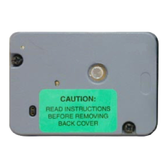
1. Open the container or door to expose the back cover of
the lock.
2. Locate the Lock On Back Cover (LOBC) Pin on the back
cover. (Figure 1)
3. With the container/door open, turn the dial to the left and fully
extend the lock bolt.
4. Dial the combination(s) to open the lock. When OP is
displayed, pull out on the LOBC Pin and continue to hold
outward pressure on the LOBC Pin while retracting the lock
bolt. If this action is successful, the Pin will "pop" out of the
locked position, and the back cover can be removed. (If
unsuccessful, repeat until successful.)
5. Remove the two back cover screws and remove the
back cover.
6. Extend the bolt by turning the dial to the left.
7. Remove the nut that holds the drive cam to the spindle using
a 5/16" nut driver. Because of the clutch in the dial, it may
be necessary to hold the drive cam while removing the nut.
Remove and save the drive cam.
8. Locate the Combo Motor. For X-09 remove the two Torx
screws. (This will require a T8 Torx wrench.) For CDX-09
remove the two flat head screws that hold the shield and
Combo Motor in place.
9. Remove the old motor (and also the shield if CDX-09.) (Figure 2)
Note the position of the Combo Motor gear. (Figure 3)
10. Remove the fence. (Figure 4)
11. Using a small Phillips screw driver, remove the screw that holds the
slide retainer. Remove the slide retainer. (Figure 5)
Caution: Do not remove metal gears. If removed, ensure roller
remains on post on back of gear, and ensure timing marks of 2
metal gears are aligned. (See Figure 6.)
Document Number 537.026 Rev. B 07/06
X-09
C
TM
oMbo
5. LOBC (Lock on Back Cover) Pin, Spring, Clip
(1 each)
6. Fence (1)
7. Slide Retainer (1)
8. Phillips Head Screw for Slide Retainer (1)
M
r
oTor
eplaCeMenT
(p/n 507101)
Figure 1 - Lock On Back Cover Pin
Combo Motor
Figure 2 - Locate Combo Motor
Figure 3 - Note Gear Position
K
iT
LOBC Pin
Home Position
Advertisement
Table of Contents

Related Manuals for Kaba Mas X-09


Summary of Contents for Kaba Mas X-09
- Page 1 4. Back Cover Screws (2) 8. Phillips Head Screw for Slide Retainer (1) To Remove the Old Motor Caution: Use of a grounding strap is necessary to prevent electrostatic discharge when performing any maintenance on the X-09 Lock. Please read instructions completely before performing any operation. 1. Open the container or door to expose the back cover of the lock.
- Page 2 1. Install the new slide retainer. (Extra screw provided.) 2. Install the new fence, ensuring that the slot in the fence is seated over the slide retainer. 3. Rotate the new Combo Motor gear so that the motor is in the home position and install the new motor. Secure with the two Torx screws for X-09 or two flat head screws for CDX-09. (Extra screws included in kit. Refer to Figures 2 and 3.) 4. Replace the drive cam and drive cam retaining nut. Once again, it may be necessary to hold the drive cam while tightening the nut.
Need help?
Do you have a question about the X-09 and is the answer not in the manual?
Questions and answers