Table of Contents
Advertisement
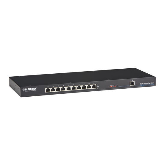
DCX KVM Matrix Switch
High-Performance Digital KVM Matrix Switch.
Shielded CAT6/CAT6A/CAT7 cables are required.
Order toll-free in the U.S. or for FREE technical support 24/7: Call 877-877-BBOX
Customer
(outside U.S. call 724-746-5500)
Support
www.blackbox.com • info@ blackbox.com
Information
DCX1000
DCX3000-DPT
DCX3000
DCX3000-DVR
DCX-VGA
DCX3000-DVT
Advertisement
Table of Contents

Subscribe to Our Youtube Channel
Related Manuals for Black Box DCX1000


Summary of Contents for Black Box DCX1000
- Page 1 DCX1000 DCX3000-DPT DCX-VGA DCX3000 DCX3000-DVR DCX3000-DVT DCX KVM Matrix Switch High-Performance Digital KVM Matrix Switch. Shielded CAT6/CAT6A/CAT7 cables are required. Order toll-free in the U.S. or for FREE technical support 24/7: Call 877-877-BBOX Customer (outside U.S. call 724-746-5500) Support www.blackbox.com • info@ blackbox.com...
- Page 2 DCX Switch Trademarks Used in this Manual Black Box and the Double Diamond logo are registered trademarks of BB Technologies, Inc. Any other trademarks mentioned in this manual are acknowledged to be the property of the trademark owners. We‘re here to help! If you have any questions about your application or our products, contact Black Box Tech Support at 877-877-2269 or go to blackbox.com and click on “Talk to Black Box.”...
- Page 3 Disclaimer: Black Box Network Services shall not be liable for damages of any kind, including, but not limited to, punitive, consequential or cost of cover damages, resulting from any errors in the product information or specifications set forth in this document and Black Box Network Services may revise this document at any time without notice.
- Page 4 DCX Switch Instrucciones de Seguridad (Normas Oficiales Mexicanas Electrical Safety Statement) 1. Todas las instrucciones de seguridad y operación deberán ser leídas antes de que el aparato eléctrico sea operado. 2. Las instrucciones de seguridad y operación deberán ser guardadas para referencia futura. 3.
-
Page 5: Table Of Contents
3.1.3 Computer connections: Data link ........................11 3.1.4 Switch (DCX1000) connections: Computer links ....................12 3.1.5 Reallocating ports ..............................12 3.1.6 Switch (DCX1000) connections: User console links .....................12 3.1.7 Switch (DCX3000) connections: Computer links ....................13 3.1.8 Reallocating ports ..............................13 3.1.9 Switch (DCX3000) connections: User console links .....................13 3.1.10 Switch connections: Network link ........................ -
Page 6: Specifications
Operating Temperature: 32 to 104°F (0 to 40°C) 1.1 Options The following options are available for your DCX installation: • DCX1000 digital matrix switch with 10 ports Part number: DCX1000 • DCX3000 digital matrix switch with 30 ports Part number: DCX3000 Part number: DCX3000-DPT •... -
Page 7: Welcome
Chapter 2: Overview 2. Welcome Thank you for choosing the Black Box DCX sys- COMPUTER COMPUTER COMPUTER COMPUTER tem. This adaptive system makes sharing numerous host computers among multiple DCX SAM DCX SAM DCX SAM DCX SAM users straightforward and flexible. Every com-... -
Page 8: Access Permissions
2.2.1 DCX1000 By default the DCX1000 Switch provides 8 computer ports (1 to 8) and 2 user console ports (9 to 10), all on its rear panel, however, these designations are not fixed. If your installation requires a greater number of consoles, you can alter the alloca-... - Page 9 Chapter 3: Installation 2.2.2 Port designations By default the DCX3000 Switch provides 10 user console ports on its front panel and 20 computer ports along its rear panel, however, these designations are not fixed. If your installation requires a greater number of computers or has a need for more user consoles, you can alter the allocation of these standard ports to suit: USERS PWR A PWR B STS...
-
Page 10: Installation
Please consider the following important points when planning the position of the DCX modules: • If used, position the DCX1000/3000 Switch in a central position that serves the host systems and user modules without exceeding the maximum link lengths. It will also require a source of mains power. -
Page 11: Computer Connections: Usb
Chapter 3: Installation 3.1.2 Computer connections: USB Each DCX SAM module requires a single USB connection to the computer. This provides essential power for the DCX SAM mod- ule in addition to the USB signals. Each DCX-DVR module acts as a USB 2.0 hub and thus provides four sockets for peripherals. 3.1.2.1 To connect the USB port 1 Connect the USB cable of the DCX SAM module to a vacant USB socket on your host computer. -
Page 12: Switch (Dcx1000) Connections: Computer Links
3.1.5 Reallocating ports The user console links are made via the sockets on the rear panel of the DCX1000 Switch provides 8 computer ports and 2 user ports along its rear panel. If necessary, these standard arrangements can be changed. See Reallocating ports. -
Page 13: Switch (Dcx3000) Connections: Computer Links
Chapter 3: Installation 3.1.7 Switch (DCX3000) connections: Computer links The host computer links are made to the sockets on the rear panel of the DCX3000 switch. 3.1.7.1 To connect a host link 1 Connect the shielded (S/FTP or S/STP) CAT6a or CAT7 cable from the remote DCX SAM host module to a vacant RJ-45 socket on the rear panel of the DCX Switch. -
Page 14: Switch Connections: Network Link
All system configuration is carried out via an Ethernet link, allowing adjustments to be made by authorized admin users located next to the DCX1000/3000 unit, or anywhere. The auto-sensing network port can determine between 10, 100Mbps or 1Gbps links and can also adjust to straight or cross-over cables. -
Page 15: Switch Connections: Power
3.1.12 Switch connections: Power Each DCX1000/3000 Switch is supplied with a single power adapter but offers the facility to use a second input in order to pro- vide operational redundancy. The switch unit can operate perfectly well from a single power adapter operating alone. When two adapters are connected, the unit will spread its load between them;... -
Page 16: Console Connections: Video
3.1.13.2 EDID management The DCX1000/3000 Switches provide a number of fixed EDID (Extended Display Identification Data) profiles that will suit a large number of video display configurations. If additional EDID definitions are required for your installation, you can clone new defini- tions from connected video displays and add these to the list of available definitions. -
Page 17: Console Connections: Usb
Chapter 3: Installation 3.1.14 Console connections: USB The DCX-DVR module contains a USB hub that can support up to four v1.1 or v2.0 USB devices (in any combination). All four USB sockets, two on the front panel and two on the rear, are identical in operation. Note: In multi-head installations, the USB devices must be attached only to the DCX-DVR that drives the main display. -
Page 18: Console Connections: Data Link
3.1.16 Console connections: Data link Each DCX-DVR module is linked via a shielded (S/FTP or S/STP) CAT6a or CAT7 cable either to a central DCX1000/3000 Switch module (multi-system matrix installation) or directly to a DCX SAM module (single system installation). -
Page 19: Console Connections: Power
Chapter 3: Installation 3.1.18 Console connections: Power There is no on/off switch on the DCX-DVR module, so operation begins as soon as power is applied. The supplied power adapter uses a locking-type plug to help prevent accidental disconnections; please follow the instructions given right whenever discon- necting a power adapter. -
Page 20: Configuration
2 Run a web browser on your computer and enter the IP address of the DCX1000/3000 Switch. The switch will attempt to contact a valid DHCP server to determine a suitable IP address. If a DHCP server cannot be located then the switch will automatically fall back to a link-local IP address (in the range 169.254.1.0 thru 169.254.254.255). - Page 21 Chapter 4: Configuration 4.1.2 To temporarily connect a computer to the network port 1 If you need to make a temporary connection for configuration purposes, use a standard patch cable (cross-over or straight connections are both supported) to link the Ethernet 10/100 network port ( ) on the front panel of the DCX3000 Switch to your computer’s network port.
-
Page 22: Using Dcx Matrix
DCX Switch 4.2 Using DCX Matrix 4.2.1 The Dashboard page Once you have successfully logged in, DCX Matrix will show the dashboard page to provide a general overview of your DCX installation. You can also re-display this page by clicking the Dashboard entry in the menu: Click the required menu Colors and symbols are used to provide quick visual Click a heading to reorder... -
Page 23: Quick Guide To Creating A New Installation
By default the DCX3000 Switch provides 20 computer ports along its rear panel and 10 user ports along its front panel (the DCX1000 provides 8 computer ports and 2 user ports). If necessary, these standard arrangements can be changed to suit your... -
Page 24: The Control Page
DCX Switch 4.4 The Control page The Control page provides a Connection map that allows the admin user to view and affect how con- soles are connected to the various computers. This page is particularly useful when managing video-only installations. 4.4.1 To connect a console 4.4.2 To disconnect a console 1 Click the down arrow on the console entry to reveal the... -
Page 25: The Configure
• Description - a further opportunity to add more information about the switch. • Location - a useful feature if you have multiple DCX1000/3000 Switches distributed around. • System Default EDID - determines the default EDID to use for the installation. - Page 26 DCX Switch 4.5.2 Central Switch > Network All of the key settings for the network capabilities of the DCX1000/3000 Switch are here: • DHCP - allows you to use DHCP (Dynamic Host Configuration Protocol) to automatically determine all network settings or set them manually. When set to On, the next three options are not editable.
- Page 27 Chapter 4: Configuration 4.5.3 Central Switch > OSD Settings Options related to the on screen display are presented in this section: • Thumbnails - when set to Off, this option will hide the thumbnail views of each computer within each user’s OSD main page.
- Page 28 DCX Switch 4.5.4 Central Switch > Manage EDIDs This page lists the EDID (Extended Display Identification Data) profiles that are currently available: • EDID - shows the resolutions and refresh rates for all profiles that are currently stored. • Type - indicates where each EDID profile originated: Fixed EDIDs are included within the switch firmware and cannot be removed.
-
Page 29: Configure > Consoles
In addition to the Name and Description, other columns provide the following details and options for each console entry: Edit • Ports - each DCX-DVR module connects to a single port on the DCX1000/3000 Click an entry to view/edit Switch. This column lists the port(s) used by the DCX-DVR module(s) associated with its details and access per- each console. - Page 30 DCX Switch 4.6.1 Add new Click the [+] icon to begin adding a new console, either before or after connecting the DCX-DVR module(s): • Name - the main identifier for the new console. • Description - a further opportunity to add more information about the console.
- Page 31 Chapter 4: Configuration 4.6.2 Configure > Consoles > Edit an entry Click on an entry within the Configure > Consoles list to display this page. Here you can edit the configuration details for a chosen console. 877-877-2269 | blackbox.com Page 31...
- Page 32 DCX Switch 4.6.2.1 Edit • Name - the main identifier for the console. • Description - a further opportunity to add more information about the console. • OSD Mouse Launch - when set to On, allows the console user to invoke the on Screen Display by holding down their center mouse button and then clicking the right button.
-
Page 33: Configure > Consoles > Remotes
Chapter 4: Configuration 4.7 Configure > Consoles > Remotes At the heart of each console (the collective term for a set of peripherals connected to the DCX system) is a remote unit called a DCX-DVR module. Click a heading to reorder the whole list in ascending or descending order according to the entries within the chosen column. - Page 34 DCX Switch 4.7.1 View remote details Click a remote entry to view the configuration details of the switch port to which it is connected. Within this page it is possible to reboot and/or recover a remote. 4.7.1.1 Recovering a remote This option (shown only when the Maintenance >...
-
Page 35: Configure > Computers
In addition to the Name and Description, the columns also provide the following useful details for each computer entry: • Port(s) - each DCX SAM module connects to a single port on the DCX1000/3000 Switch. This column lists the port(s) used by the DCX SAM module(s) associated with each computer. Two or more DCX SAM modules can be combined to support extra displays (multi-head), each connecting to a separate port. - Page 36 DCX Switch 4.8.1 Add new Click the [+] icon to begin adding a new computer, either before or after connecting the DCX SAM module(s): • Name - the main identifier for the new computer. • Description - a further opportunity to add more information about the computer.
- Page 37 Chapter 4: Configuration 4.8.2 Configure > Computers > Edit an entry This page allows you to edit the configuration details for a chosen computer. • Name - the main identifier for the computer. • Description - a further opportunity to add more information about the computer.
-
Page 38: Configure > Computers > Locals
DCX Switch 4.9 Configure > Computers > Locals Each computer connects to a DCX SAM module. This page lists each DCX SAM module and their key details: Click a heading to reorder the whole list in ascending or descending order according to the entries within the chosen column. - Page 39 Chapter 4: Configuration 4.9.1 View local module details Click a locals entry to view the configuration details of the switch port to which it is connected. Within this page it is possible to reboot and/or recover a remote. 4.9.1.1 Applying a different EDID If a computer needs to use an EDID profile that differs from the one being used as the default System EDID, use these steps: 1 If necessary, clone the required EDID - see...
-
Page 40: Reallocating Ports
By default the DCX1000/3000 Switch provide the following user console and computer ports: • DCX1000 provides 2 user console ports and 8 computer ports (along its rear panel). • DCX3000 provides 10 user console ports (on its front panel) and 20 computer ports (along its rear panel). -
Page 41: The Users Page
Chapter 4: Configuration 4.11 The Users page This page lists all registered users and allows the admin user to add, edit and delete entries, as required. Note: When changes are made to user details, you are recommended to make a backup file. Add new Click the [+] icon to begin adding a new user. -
Page 42: The Maintenance
DCX Switch 4.12 The Maintenance pages The Maintenance section contains three pages: Diagnostics, System Operations and Settings. 4.12.1 Maintenance > Diagnostics This page provides important feedback on power inputs (and switch Temperatures). The temperature information is displayed only when the Maintenance > Settings > Web UI Mode is set to Advanced. This section indicates the status of the mains power input(s). - Page 43 DCX Matrix. choose the filename and location. Note: In order to support DCX1000 models, only backup files created with Version 2.01 firmware or above are supported. Any Backup file taken with V2.00 or below firmware will not be restored on a V2.01 switch. This prevents a 30 port backup file being uploaded to a 10 port switch.
- Page 44 DCX Switch 4.12.3 Maintenance > Settings This page provides options related to the user interface. When you make a change, you need to click the Update button to save it. Web UI Mode When this option is set to Advanced, extra details are shown on certain pages, such as: •...
-
Page 45: Resetting And Recovering
4.13 Resetting and recovering There may be rare occasions when the main switch or a module needs to be given a hard reset. The DCX1000/3000 Switch and DCX-DVR module both have concealed reset buttons for this purpose. You need to use a narrow implement (e.g. a straightened- out paper clip) to press-and-hold the recessed reset button on the front panel: 4.13.1 DCX1000/3000 Switch... - Page 46 DCX Switch 4.13.2 DCX-DVR module 4.13.2.1 DCX-DVR module > Boot into recovery mode This procedure may be necessary if an attempted firmware upgrade has failed. For such a situation the DCX-DVR module always retains a recovery image that will return the unit to a working condition, prior to reattempting a firmware upgrade. 1 Press-and-hold the recessed reset button for ten seconds until the PWR indicator begins to flash quickly.
-
Page 47: Operation
Chapter 5: Operation 5. Operation The DCX system is designed to be transparent in operation. A simple OSD (On Screen Display) interface allows each user to view and select from the available host computers. Note: The default OSD resolution is 1920 x 1080. If your video display does not support this resolution, see Central Switch >... -
Page 48: Choosing A Computer
DCX Switch 5.2 Choosing a computer 5.2.1 To choose a computer using the mouse 1 Display the OSD from your console using either of the methods shown on the previous page. 2 Hover the mouse pointer over the required screen image. A set of popup connection icons will be displayed: View only - you can view a computer’s output but not alter it, •... -
Page 49: Using Audio
The DCX system fully supports stereo audio, with all audio devices being presented at the linked host computer as USB audio devices. There are slight differences in audio operation between DCX1000/3000 devices acting in a simple extender arrangement (without the use of a DCX1000/3000 Switch) and a full DCX matrix installation. -
Page 50: Indicators
DCX Switch 5.4 Indicators The DCX1000/3000 Switches, the DCX SAM and DCX-DVR modules contain various indicators to provide you with status infor- mation. 5.4.1 DCX1000/3000 Switch - Red front panel status indicators The red status indicators on DCX1000/3000 Switch front panels provide various key power and operation feedback:... - Page 51 Flashing: Power present but Slow flashing: Power present but no data link no video Fast flashing: A firmware upgrade is being forced by either the DCX1000/3000 Switch or a DCX-DVR Power present and Power present and link established video locked 877-877-2269 | blackbox.com...
-
Page 52: Appendix A. Safety Information
DCX Switch Appendix A. Safety Information • For use in dry, oil free indoor environments only. • Do not use to link between buildings. • Ensure that the twisted pair interconnect cable is installed in compliance with all applicable wiring regulations. •... -
Page 53: Appendix B. Firmware Upgrades For Basic Extender Installations
Appendices Appendix B. Firmware upgrades for basic extender installations Extender systems (or individual DCX-DVR units) can be upgraded using a USB stick if required. This is carried out as follows: 1 Connect the DCX-DVR to a compatible display and keyboard; optionally connect to a DCX SAM module using a CATx data cable to upgrade it at the same time. -
Page 54: Appendix C. Link Cable Interference Protection
DCX Switch Appendix C. Link cable interference protection While the Category rating (e.g. CAT 5e, CAT 6a, CAT 7, etc.) determines the electrical performance of a cable, another vital part of the overall cable specification is its protection from interference. As cabling distances and data rates increase, so too does the susceptibility to interference, from both external and internal sources. - Page 55 About Black Box Black Box provides an extensive range of networking and infrastructure products. You’ll find everything from cabinets and racks and power and surge protection products to media converters and Ethernet switches all supported by free, live 24/7 Tech support available in 60 seconds or less.
Need help?
Do you have a question about the DCX1000 and is the answer not in the manual?
Questions and answers