Table of Contents
Advertisement
Quick Links
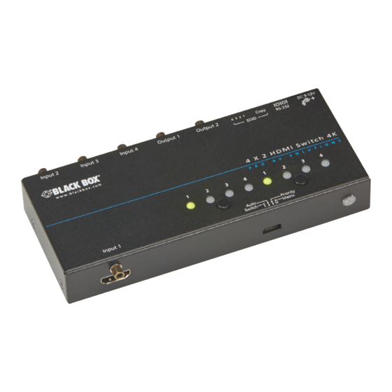
4K HDMI Matrix Switch—2 x 2 or 4 x 2
Switch one of two or four HDMI source devices
to one or two HDMI displays.
Supports 4K HDMI formats with RS-232 serial or IR remote control.
Order toll-free in the U.S.: Call 877-877-BBOX (outside U.S. call 724-746-5500)
Customer
FREE technical support 24 hours a day, 7 days a week: Call 724-746-5500 or fax 724-746-0746
Support
www.blackbox.com • info@blackbox.com
Information
VSW-HDMI2X2-4K
VSW-HDMI4X2-4K
Advertisement
Table of Contents

Related Manuals for Black Box VSW-HDMI2X2-4K


Summary of Contents for Black Box VSW-HDMI2X2-4K
- Page 1 VSW-HDMI2X2-4K VSW-HDMI4X2-4K 4K HDMI Matrix Switch—2 x 2 or 4 x 2 Switch one of two or four HDMI source devices to one or two HDMI displays. Supports 4K HDMI formats with RS-232 serial or IR remote control. Order toll-free in the U.S.: Call 877-877-BBOX (outside U.S. call 724-746-5500)
- Page 2 Trademarks Used in this Manual Trademarks Used in this Manual Black Box and the Double Diamond logo are registered trademarks of BB Technologies, Inc. HDMI is a registered trademark of HDMI Licensing L.L.C. UL is a registered trademark of Underwriters Laboratories.
- Page 3 FCC and IC RFI Statements Federal Communications Commission and Industry Canada Radio Frequency Interference Statements This equipment generates, uses, and can radiate radio-frequency energy, and if not installed and used properly, that is, in strict accordance with the manufacturer’s instructions, may cause inter ference to radio communication. It has been tested and found to comply with the limits for a Class A computing device in accordance with the specifications in Subpart B of Part 15 of FCC rules, which are designed to provide reasonable protection against such interference when the equipment is operated in a commercial environment.
- Page 4 NOM Statement Instrucciones de Seguridad (Normas Oficiales Mexicanas Electrical Safety Statement) 1. Todas las instrucciones de seguridad y operación deberán ser leídas antes de que el aparato eléctrico sea operado. 2. Las instrucciones de seguridad y operación deberán ser guardadas para referencia futura. 3.
-
Page 5: Table Of Contents
2. Overview ....................................7 2.1 Introduction ...................................7 2.2 Features ..................................7 2.3 What’s Included ................................8 2.4 Hardware Description ..............................9 2.4.1 VSW-HDMI2X2-4K ...............................9 2.4.2 VSW-HDMI4X2-4K ............................11 3. Installation ................................... 14 3.1 Device Connection ..............................14 3.2 Connection Pattern ..............................14 4. Operation .................................... -
Page 6: Specifications
1280 x 720p EDID Configuration: Video: Auto/inventory, Audio: Auto/inventory Mode Configuration: Switch/Autosensing/Priority/Matrix Interface HDMI Ports: Input: VSW-HDMI2X2-4K: (2) HDMI female, VSW-HDMI4X2-4K: (4) HDMI female, Output: (2) HDMI female Serial Port: VSW-HDMI2X2-4K or VSW-HDMI4X2-4K: (1) RJ-12 female IR Controls: VSW-HDMI2X2-4K or VSW-HDMI4X2-4K::... -
Page 7: Overview
Chapter 2: Overview 2. Overview 2.1 Introduction The 4K HDMI Matrix Switch—2 x 2 or 4 x 2—routes two or four HDMI sources to two HDMI displays (projectors, monitors, and so on). It displays the same image from one video source to all monitors or images from different video sources to different monitors. -
Page 8: What's Included
3. Click on the “Resources” tab on the product page, and select the document you wish to download. If you have any trouble accessing the Black Box site to download the manual, you can contact our Technical Support at 724-746-5500 or info@blackbox.com. -
Page 9: Hardware Description
Chapter 2: Overview 2.4 Hardware Description 2.4.1 VSW-HDMI2X2-4K Figure 2-1. VSW-HDMI2X2-4K front panel. Figure 2-2. VSW-HDMI2X2-4K back panel. 11, 12 9, 10 Figure 2-3. VSW-HDMI2X2-4K top panel. 724-746-5500 | blackbox.com Page 9... - Page 10 Chapter 2: Overview Table 2-1. VSW-HDMI2X2-4K components. Number in Figure Component Description 2-1, 2-2, or 2-3 1, 2 Video input 1 and 2 Connect to an HDMI video source 3, 4 Video Output 1 and 2 Connect to an HDMI display...
-
Page 11: Vsw-Hdmi4X2-4K
Chapter 2: Overview 2.4.2 VSW-HDMI4X2-4K Figure 2-4. VSW-HDMI4X2-4K front panel. Figure 2-5. VSW-HDMI4X2-4K back panel. 14, 15, 16, 17 10, 11, 12, 13 Figure 2-6. VSW-HDMI4X2-4K top panel. 724-746-5500 | blackbox.com Page 11... - Page 12 Chapter 2: Overview Table 2-2. VSW-HDMI4X2-4K components. Number in Figure 2-4, Component Description 2-5, or 2-6 1, 2, 3, 18 Video Input 1, 2, 3, and 4 Connect to an HDMI video source 4, 5 Video Output 1 and 2 Connect to an HDMI display Audio/Video EDID Setting Switch Configure Audio/Video EDID Setting...
- Page 13 Chapter 2: Overview Slide Switch EDID Setting switch Figure 2-7. Audio/Video EDID Setting switch on back panel of Matrix Switch. Table 2-3. Slide switch settings. Mode Video Audio Auto Auto Auto Inventory Inventory Auto Inventory Inventory NOTE: For more operation details, refer to the Operation section. Advanced Auto-sensing Setting Switch Figure 2-8.
-
Page 14: Installation
Chapter 3: Installation 3. Installation WARNING: • Before installing the switch, power off all devices that will be connected to this system. • Make sure that all devices you will connect are properly grounded. • Place cables away from fluorescent lights, air conditioners and machines that are likely to generate electrical noise. 3.1 Device Connection 1. -
Page 15: Operation
Chapter 4: Operation 4. Operation Video Input Status LED 1 and 2 IR sensor Video Output Status LED 1 and 2 Figure 4-1. LEDs on the top panel of the 2 x 2 switch. Video Input Status LED 1, 2, 3, and 4 Video Output Status IR sensor LED 1, 2, 3 and 4... -
Page 16: Push Button Control
Chapter 4: Operation Table 4-1. LED indicators on the unit. Input or Output in Switch/Auto/Priority Modes Status Figure 4-1 or 4-2 Video Input The selected LED emits green and goes The input video signal isn't ready. Status LED 1 off 3 times per 2 seconds. Video Input The selected LED emits green and goes The input video signal is ready but cannot detect the monitor. -
Page 17: Edid Setting
Chapter 4: Operation 4.2.2 EDID Setting NOTE: Before starting, slide the Audio/Video EDID Setting Switch to position 2/3/4. EDID Setting switch Figure 4-3. EDID Setting switch on back panel of Matrix Switch. Copy Monitor EDID (2 methods): Method 1 Step 1: Apply power to the unit. Step 2: Connect the (EDID compliant) monitor to the output port of the unit and power on the monitor. - Page 18 Chapter 4: Operation EDID Emulation Slide the switch to the desired position as shown below. EDID Setting switch Figure 4-2. Audio/Video EDID Setting switch on back panel of Matrix Switch. Table 4-2. Slide switch settings. Mode Video Audio Auto (Va) Auto (Aa) Auto (Va) Inventory (Ai)
-
Page 19: Eq Adjustment
Chapter 4: Operation 4.2.3 EQ Adjustment EDID Copy button Figure 4-3. EQ Adjustment switch on the units. Press the BTNB and EDID Copy buttons for 3 seconds and release right after the (left) LED L1–L4 flash red. (LED L1–L4 indicates which level is on). -
Page 20: Ir Remote Control
Chapter 4: Operation 4.3 IR Remote Control • A/V Source selection: - Switch Mode (Switch, Auto, Priority) Press 1/ 2/3/4: Select Source1/Source 2/Source 3/Source 4. - Matrix Mode (2-BUS) For BUS-A (Monitor 1): Press 1/2/3/4: Select Source1/Source 2/Source 3/Source 4. For BUS-B ((Monitor 2): Press S1/S2/S3/S4: Select Source1/Source 2/Source 3/Source 4. -
Page 21: Serial Configuration
Chapter 5: Serial Configuration 5. Serial Configuration The HDMI Switch-Splitter with built-in serial interface allows users to control the unit via a PC, serial controller devices, or a home theater system. Configure the ontroller’s serial port as shown below: Baud Rate: 38400 bps Data Bits: 8 Parity: None Stop Bits: 1... -
Page 22: Gui Over Serial
Chapter 5: Serial Configuration 5.2 GUI over Serial The switch-splitter allows users to control the unit by GUI operation via a built-in serial interface. Follow the installation and operation steps described next. 1. Installing Application A serial console (PC) running Windows 98/2000/X/Vista/7 is required to install the appropriate software. Follow the step-by-step instructions listed below. - Page 23 Chapter 5: Serial Configuration The window shown below pops up next. Figure 5-3. AV Console Center screen. Step 1: Open “Tools” on the tool bar, and select “Communication Port.” Figure 5-4. Tools drop-down menu. Step 2: Check “COM Port” and choose the serial port you want to connect, such as COM1, and set the Baud Rate as “38400.” Figure 5-5.
- Page 24 Chapter 5: Serial Configuration Step 3: A dialog box will pop out indicating device(s) detected. Figure 5-6. Devices detected OK prompt. Step 4: Double-click “Digital Switch-Splitter” on the left block. (There are other ways to detect the device. For more information, refer to Toolbar Guidance/Action.) Figure 5-7.
- Page 25 Chapter 5: Serial Configuration Table 5-1. Topology file options. Number Option Function Open Existing Topology Open pre-stored topology file Save Current Topology Allow users to save current topology file in the location where the software is installed. Save Current Topology As… Allow users to save current topology file in the requested location.
-
Page 26: Advanced Operation
Chapter 5: Serial Configuration Table 5-2. GUI option functions. Number Option Function Auto apply Automatically apply settings. We do not recommend checking this item, because it could slow down the system. Apply Activates the settings. Detect and show the current setting status. Users can operate the unit via front panel push button or IR remote controller. - Page 27 Chapter 5: Serial Configuration Figure 5-12. Method copy screen. Table 5-4. Method Operation Steps. Method Operation Steps Copy selected input port EDID as factory Step 1. Check the desired input port(s) or check All input ports to select all. default. Step 2.
- Page 28 Chapter 5: Serial Configuration Changing Source/Display Icon: Double-click the source/display icon and a pop-up window will appear. Users may change the icon and name the selected source or display. Name the display/source: Click the corresponding icon and insert any name you want. Change the icon: a.
- Page 29 NOTES 724-746-5500 | blackbox.com Page 29...
- Page 30 NOTES 724-746-5500 | blackbox.com Page 30...
- Page 31 NOTES 724-746-5500 | blackbox.com Page 31...
- Page 32 About Black Box Black Box provides an extensive range of networking and infrastructure products. You’ll find everything from cabinets and racks and power and surge protection products to media converters and Ethernet switches all supported by free, live 24/7 Tech Support available in 60 seconds or less.
Need help?
Do you have a question about the VSW-HDMI2X2-4K and is the answer not in the manual?
Questions and answers