Table of Contents
Advertisement
Quick Links
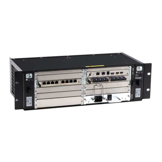
ServSwitch
™
Provides flexible and super-fast crosspoint
switching of Full HD video in KVM enterprises.
Order toll-free in the U.S.: Call 877-877-BBOX (outside U.S. call 724-746-5500)
Customer
FREE technical support 24 hours a day, 7 days a week: Call 724-746-5500 or fax
Support
724-746-0746 • Mailing address: Black Box Corporation, 1000 Park Drive, Lawrence,
Information
PA 15055-1018 • Web site: www.blackbox.com • E-mail: info@blackbox.com
ACX048
ACX080
ACX160
ACX288
DKM FX and DKM FX Compact
ACXC8
ACXC32
ACXC8F
ACXC32F
ACXC16
ACXC48
ACXC16F
ACXC48F
ACXC64
ACXC48F16
ACXC64F
ACXC48F32
ACXC80
ACXC80F
Advertisement
Table of Contents

Related Manuals for Black Box ServSwitch DKM FX


Summary of Contents for Black Box ServSwitch DKM FX
- Page 1 Order toll-free in the U.S.: Call 877-877-BBOX (outside U.S. call 724-746-5500) Customer FREE technical support 24 hours a day, 7 days a week: Call 724-746-5500 or fax Support 724-746-0746 • Mailing address: Black Box Corporation, 1000 Park Drive, Lawrence, Information PA 15055-1018 • Web site: www.blackbox.com • E-mail: info@blackbox.com...
- Page 2 Any other trademarks mentioned in this manual are acknowledged to be the property of the trademark owners. NOTE: The ServSwitch DKM FX and the ServSwitch DKM FX Compact function in similar ways. The difference between them is described in the table below.
- Page 3 FCC and IC RFI Statements/NOM Statement FEDERAL COMMUNICATIONS COMMISSION AND INDUSTRY CANADA RADIO FREQUENCY INTERFERENCE STATEMENTS This equipment generates, uses, and can radiate radio-frequency energy, and if not installed and used properly, that is, in strict accordance with the manufacturer’s instructions, may cause inter ference to radio communication. It has been tested and found to comply with the limits for a Class A computing device in accordance with the specifications in Subpart B of Part 15 of FCC rules, which are designed to provide reasonable protection against such interference...
- Page 4 NOM Statement 4. Todas las instrucciones de operación y uso deben ser seguidas. 5. El aparato eléctrico no deberá ser usado cerca del agua—por ejemplo, cerca de la tina de baño, lavabo, sótano mojado o cerca de una alberca, etc. 6.
- Page 5 NOM Statement 17. Cuidado debe ser tomado de tal manera que objectos liquidos no sean derramados sobre la cubierta u orificios de ventilación. 18. Servicio por personal calificado deberá ser provisto cuando: A: El cable de poder o el contacto ha sido dañado; u B: Objectos han caído o líquido ha sido derramado dentro del aparato;...
- Page 6 • Only use the device according to this user manual. • Only use in dry, indoor environments. • The ServSwitch DKM FX and the power supply units can get warm. Don’t put them in an enclosed space without any airflow.
-
Page 7: Table Of Contents
2.5.6 ServSwitch DKM FX Compact 8-Port, Fiber (ACXC8F) ..32 2.5.7 ServSwitch DKM FX Compact 16-Port (ACXC16) ....33 2.5.8 ServSwitch DKM FX Compact 16-Port, Fiber (ACXC16F) ..34 2.5.9 ServSwitch DKM FX Compact 32-Port (ACXC32) ....35 2.5.10 ServSwitch DKM FX Compact 32-Port, Fiber (ACXC32F) ..36 2.5.11 ServSwitch DKM FX Compact 48-Port (ACXC48) ....37... - Page 8 Table of Contents Chapter ..................Page 2.5.12 ServSwitch DKM FX Compact 48-Port, Fiber (ACXC48F) ..38 2.5.13 ServSwitch DKM FX Compact 64-Port (ACXC64) ....39 2.5.14 ServSwitch DKM FX Compact 80-Port, Fiber (ACXC64F) ..40 2.5.15 ServSwitch DKM FX Compact 80-Port (ACXC80) ....41...
- Page 9 Table of Contents Chapter ..................Page 4.3 Assignment ..................96 4.3.1 Virtual CPU ................96 4.3.2 Virtual Console ..............98 4.4 System Settings ................101 4.4.1 System Data ................101 4.4.2 Automatic ID ..............104 4.4.3 Access ................106 4.4.4 Switch ................109 4.4.5 Network ................
- Page 10 7.2 Video Interference .................218 7.3 Fans Malfunction ................218 7.4 Power Supply Units Malfunction ...........219 7.5 Network Error ................219 7.6 ServSwitch DKM FX Failure ............219 7.7 Blank Screen ................. 220 7.8 Contacting Black Box..............220 7.9 Shipping and Packaging ..............221 Appendix. Glossary ..................222 Page 10 724-746-5500 | blackbox.com...
-
Page 11: Specifications
Chapter 1: Specifications 1. Specifications 1.1 Interfaces 1.1.1 DVI-D Single Link The video interface supports the DVI-D protocol. All signals that comply with DVI-D single-link standard can be transmitted. This includes, for example, monitor resolutions such as 1920 x 1200 @ 60 Hz, Full HD (1080p), or 2K HD (up to 2048 x 1152). -
Page 12: Serial)
NOTE: To maintain regulatory EMC compliance, all CATx cables need to carry ferrites on both cable ends close to the device. Type of Interconnect Cable The ServSwitch DKM FX requires interconnect cabling specified for Gigabit Ethernet (1000BASE-T). Use solid-core (24 AWG), shielded, CAT5e (or better) cable. -
Page 13: Fiber
Chapter 1: Specifications Table 1-1. CATx interconnect cable. Cable Type Description This S/UTP (CAT5e) cable confoms to EIA/TIA-568-B. CATx solid-core 24 AWG cable Uses four pairs of 24 AWG wires. Connects according to EIA/TIA-568-B (1000BASE-T). This S/UTP (CAT5e) cable confoms to EIA/TIA-568-B. CATx solid-core 26/8 AWG cable Uses four pairs of 26/8 AWG wires. -
Page 14: Coaxial
Chapter 1: Specifications Table 1-4. Maximum acceptable fiber cable length. Cable Type Distance Single-mode 9-µm 32,800 ft. (10,000 m) Multimode 50-µm (OM3) 3280 ft. (1000 m) Multimode 50-µm 1300 ft. (400 m) Multimode 62.5µm 650 ft. (200 m) NOTE: If you use single-mode SFPs with multimode fiber optic cable, you can double the maximum acceptable cable length. -
Page 15: Connector Pinouts
Chapter 1: Specifications 1.3 Connector Pinouts 1.3.1 CPU Board Figure 1-1. DVI-D single-link connector. Table 1-7. DVI-D single-link connector pinout. Signal Signal Signal T.M.D.S. data 2- T.M.D.S. data 1- T.M.D.S. data 0- T.M.D.S. data 2+ T.M.D.S. data 1+ T.M.D.S. data 0+ T.M.D.S. -
Page 16: I/O Board Catx
Chapter 1: Specifications Table 1-9. DB9 (serial) connector. Picture Signal Color Signal Not connected Not connected — — Table 1-10. RJ-45 connector. Picture Signal Color Signal Not connected Not connected Not connected Not connected 1.3.2 I/O Board CATx Table 1-11. RJ-45 CATx connector. Picture Signal Color... -
Page 17: I/O Board Sdi
Chapter 1: Specifications 1.3.4 I/O Board SDI Table 1-13. RJ-45 connector. Picture Signal Data In 1.4 Power Supply, Environment, Dimensions, and Weight Power ACXC48, ACXC48F, ACXC32, ACXC32F, ACXC16, ACXC16F: 1.4 A, 100–240 VAC, 50–60 Hz internal power supply; ACXC80, ACXC80F, ACXC64, ACXC64C, ACXC48F32, ACXC48F16: 2.3 A, 100–240 VAC, 50–60 Hz;... - Page 18 Chapter 1: Specifications Specifications Dimensions ACX288: 19"H x 22.8"W x 12"D (48.3 x 57.8 x 33 cm), Shipping box: 25.6"H x 26.8"W x 29.9"D (65 x 68 x 76 cm); ACX160: 19"H x 15.8"W x 12"D (48.3 x 40 x 33 cm), Shipping box: 25.6"H x 26.8"W x 12"D (65 x 68 x 54 cm);...
- Page 19 Chapter 1: Specifications Specifications MTBF The mean time between failure (MTBF) in power-on hours (POH) is listed here. The estimate is based on the FIT rates of the parts included. FIT rates are based on normalized environ- mental conditions of T = 60°C and activation energy (Ea) of 0.7 eV.
- Page 20 Chapter 1: Specifications Specifications MTBF (continued) ACXC48: Chassis: 140,000; Per fan: 280,000 POH, Per PSU: 295,700; ACXC48F: Chassis: 133,400; Per fan: 280,000 POH, Per PSU: 295,700; ACXC32: Chassis: 165,300; Per fan: 280,000 POH, Per PSU: 295,700; ACXC32F: Chassis: 161,200; Per fan: 280,000 POH, Per PSU: 295,700;...
-
Page 21: Overview
KVM extenders or video sources, you can use CATx, fiber, or coaxial cables, depending on the hardware used. The ServSwitch DKM FX serves as a repeater. You can place it up to 6.2 miles (10 km) from the consoles and 6.2 miles (10 km) from the sources. -
Page 22: Access Options
Serial interface 2.2 System Overview A ServSwitch DKM FX system consists of a ServSwitch DKM FX or DKM FX Compact and, for KVM applications, one or more CPU units/CON units. The ServSwitch connects to the CPU units/CON units by interconnect cables (copper or fiber) or is connected directly to the video devices when used as a video matrix. - Page 23 Figure 2-1. System overview. Table 2-2. System components. Number Component Computer/Server or Video Source CPU units (Transmiters) Interconnect cable ServSwitch DKM FX or FXC CON units (Receivers) User Station/Console See Section 3.2 for installation examples. Page 23 724-746-5500 | blackbox.com...
-
Page 24: Available Products
ServSwitch DKM FX 48-port with control card and power supply ACX080 ServSwitch DKM FX 80-port with control card and power supply ACX160 ServSwitch DKM FX 160-port with control card and (2) power supplies ACX288 ServSwitch DKM FX 288-port with control card and (2) power supplies ServSwitch DKM FX Compact... - Page 25 Table 2-3 (continued). Available products. Number Description Accessories (continued) ACXI08-G G 8-port universal I/O module that can support third-party SFPs ACX288-CTL ServSwitch DKM FX controller card ACXSFPC CATx SFP module ACXSFPS Single-mode fiber SFP module ACXSFPHS Single-mode fiber SFP module 3.125 Gbps...
-
Page 26: What's Included
Chapter 2: Overview 2.4 What’s Included Your package should contain the following items. If anything is missing or damaged, contact Black Box Technical Support at 724-746-5500 or info@blackbox.com. ACX048, ACX080, ACX160, ACX288, ACXC8, ACXC8F, ACXC16, ACXC16F, ACXC32, ACXC32F, ACXC48, ACXC48F, ACXC48F16, ACXC48F32, ACXC64, ACXC64F, ACXC80, ACXC80F: •... -
Page 27: Device Views
NOTE: The following images of the chassis are fully populated with I/O cards and are intended to be example diagrams. The chassis do not come with any I/O cards. You need to purchase the I/O cards separately. 2.5.1 ServSwitch DKM FX 48-Port (ACX048) Figure 2-2. Front view, ACX048. Table 2-4. ACX048 components. -
Page 28: Servswitch Dkm Fx 80-Port (Acx080)
Chapter 2: Overview 2.5.2 ServSwitch DKM FX 80-Port (ACX080) Figure 2-3. Front view, ACX080. Table 2-5. ACX080 components. Number Component Slot for fan tray Slot for Power Supply Unit 1 Slot for I/O Boards 1–10 Slot for Power Supply Unit 2... -
Page 29: Servswitch Dkm Fx 160-Port (Acx160)
Chapter 2: Overview 2.5.3 ServSwitch DKM FX 160-Port (ACX160) Figure 2-4. Front view, ACX160. Table 2-6. ACX160 components. Number Component Slot for Power Supply Unit 1 Slot for Fan Tray 1 Slot for Power Supply Unit 2 Slot for Fan Tray 2 Slot for I/O Boards 1–36... -
Page 30: Servswitch Dkm Fx 288-Port (Acx288)
Chapter 2: Overview 2.5.4 ServSwitch DKM FX 288-Port (ACX288) 6 7 8 Figure 2-5. Front view, ACX288. Page 30 724-746-5500 | blackbox.com... -
Page 31: Servswitch Dkm Fx Compact 8-Port (Acxc8)
Slot for I/O Boards 1–36 Slot for Power Supply Unit 3 Grounding Slot for CPU board NOTE: The ServSwitch DKM FX Compact models are described next. 2.5.5 ServSwitch DKM FX Compact 8-Port, CATx (ACXC8) Figure 2-6. Front view, ACXC8. Table 2-8. ACXC8 components. -
Page 32: Servswitch Dkm Fx Compact 8-Port, Fiber (Acxc8F)
Chapter 2: Overview 2.5.6 ServSwitch DKM FX Compact 8-Port, SFP (ACXC8F) Figure 2-7. Front view, ACXC8F. Table 2-9. ACXC8F components. Number Component I/O ports 1–8 (SFP) Serial connection (RJ-45) Network connection (RJ-45) Connect to power supply Connect to a 5-VDC power supply (redundancy, optional) Page 32 724-746-5500 | blackbox.com... -
Page 33: Servswitch Dkm Fx Compact 16-Port (Acxc16)
Chapter 2: Overview 2.5.7 ServSwitch DKM FX Compact 16-Port (ACXC16) Figure 2-8. Front view, ACXC16. Table 2-10. ACXC16 components. Number Component I/O ports 1–16 (CATx) Serial connection (RJ-45) Network connection (RJ-45) Figure 2-9. Back view, ACXC16. Table 2-11. ACXC16 back-panel components. -
Page 34: Servswitch Dkm Fx Compact 16-Port Fiber (Acxc16F)
Chapter 2: Overview 2.5.8 ServSwitch DKM FX Compact 16-Port Fiber (ACXC16F) Figure 2-10. Front view, ACXC16F. Table 2-12. ACXC16F components. Number Component I/O ports 1–16 (SFP) Serial connection (RJ-45) Network connection (RJ-45) Figure 2-11. Back view, ACXC16F. Table 2-13. ACXC16F back-panel components. -
Page 35: Servswitch Dkm Fx Compact 32-Port (Acxc32)
Chapter 2: Overview 2.5.9 ServSwitch DKM FX Compact 32-Port (ACXC32) Figure 2-12. Front view, ACXC32. Table 2-14. ACXC32 components. Number Component I/O ports 1–16 (CATx) I/O ports 17–32 (CATx) Serial connection (RJ-45) Network connection (RJ-45) Figure 2-13. Back view, ACXC32. -
Page 36: Servswitch Dkm Fx Compact 32-Port Fiber (Acxc32F)
Chapter 2: Overview 2.5.10 ServSwitch DKM FX Compact 32-Port Fiber (ACXC32F) Figure 2-14. Front view, ACXC32F. Table 2-16. ACXC32F components. Number Component I/O ports 1–16 (SFP) I/O ports 17–32 (SFP) Serial connection (RJ-45) Network connection (RJ-45) Figure 2-15. Back view, ACXC32F. -
Page 37: Servswitch Dkm Fx Compact 48-Port (Acxc48)
Chapter 2: Overview 2.5.11 ServSwitch DKM FX Compact 48-Port (ACXC48) Figure 2-16. Front view, ACXC48. Table 2-18. ACXC48 front-panel components. Number Component I/O ports 1–16 (CATx) I/O ports 17–32 (CATx) I/O ports 33–48 (CATx) Serial connection (RJ-45) Network connection (RJ-45) Figure 2-17. -
Page 38: Servswitch Dkm Fx Compact 48-Port Fiber (Acxc48F)
Chapter 2: Overview 2.5.12 ServSwitch DKM FX Compact 48-Port Fiber (ACXC48F) Figure 2-18. Front view, ACXC48F. Table 2-20. ACXC48F front-panel components. Number Component I/O ports 1–16 (SFP) I/O ports 17–32 (SFP) I/O ports 33–48 (SFP) Serial connection (RJ-45) Network connection (RJ-45) Figure 2-19. -
Page 39: Servswitch Dkm Fx Compact 64-Port (Acxc64)
Chapter 2: Overview 2.5.13 ServSwitch DKM FX Compact 64-Port Figure 2-20. Front view, ACXC64. Table 2-22. ACXC64 components. Number Component I/O ports 1–16 (CATx) I/O ports 49–64 (CATx) I/O ports 17–32 (CATx) I/O ports 33–48 (CATx) Serial connection (RJ-45) Network connection (RJ-45) Figure 2-21. -
Page 40: Servswitch Dkm Fx Compact 80-Port, Fiber (Acxc64F)
Chapter 2: Overview 2.5.14 ServSwitch DKM FX Compact 64-Port Fiber (ACXC64F) Figure 2-22. Front view, ACXC64F. Table 2-24. ACXC64F components. Number Component I/O ports 1–16 (SFP) I/O ports 49–64 (SFP) I/O ports 17–32 (SFP) I/O ports 33–48 (SFP) Serial connection (RJ-45) Network connection (RJ-45) Figure 2-23. -
Page 41: Servswitch Dkm Fx Compact 80-Port (Acxc80)
Chapter 2: Overview 2.5.15 ServSwitch DKM FX Compact 80-Port (ACXC80) Figure 2-24. Front view, ACXC80. Table 2-26. ACXC80 components. Number Component I/O ports 1–16 (CATx) I/O ports 49–64 (CATx) I/O ports 17–32 (CATx) I/O ports 65–80 (CATx) I/O ports 33–48 (CATx) -
Page 42: Servswitch Dkm Fx Compact 80-Port Fiber (Acxc80F)
Chapter 2: Overview 2.5.16 ServSwitch DKM FX Compact 80-Port Fiber (ACXC80F) Figure 2-26. Front view, ACXC80F. Table 2-28. ACXC80F components. Number Component I/O ports 1–16 (SFP) I/O ports 49–64 (SFP) I/O ports 17–32 (SFP) I/O ports 65–80 (SFP) I/O ports 33–48 (SFP) -
Page 43: Servswitch Dkm Fx Compact 48 Catx Ports, 16 Fiber Ports (Acxc48F16)
Chapter 2: Overview 2.5.17 ServSwitch DKM FX Compact 48 CATx Ports, 16 Fiber Ports (ACXC48F16) Figure 2-28. Front view, ACXC48F16. Table 2-30. ACXC48F16 components. Number Component I/O ports 1–16 (CATx) I/O ports 49–64 (SFP) I/O ports 17–32 (CATx) I/O ports 33–48 (CATx) -
Page 44: Servswitch Dkm Fx Compact 48 Catx Ports, 32 Fiber Ports (Acxc48F32)
Chapter 2: Overview 2.5.18 ServSwitch DKM FX Compact 48 CATx Ports, 32 Fiber Ports (ACXC48F32) Figure 2-30. Front view, ACXC48F32. Table 2-32. ACXC48F32 components. Number Component I/O ports 1–16 (CATx) I/O ports 49–64 (SFP) I/O ports 17–32 (CATx) I/O ports 65–80 (SFP) I/O ports 33–48 (CATx) -
Page 45: Diagnostics And Status
Chapter 2: Overview 2.6 Diagnostics and Status 2.6.1 Status LEDs The ServSwitch DKM FX and DKM FX Compact LED indicators are shown in Figures 2-12 through 2-22, and described in Tables 2-14 through 2-25. Figure 2-32. CPU board, front view. - Page 46 Chapter 2: Overview Table 2-34. Status LEDs on the CPU board. Number Status Description White CPU board is in registration process Blue flashing Registration at the matrix is started Status 1 Red flashing Registration is in progess Green flashing Operating condition Green CPU board de-registered White...
- Page 47 Chapter 2: Overview Table 2-35. Status LEDs on the I/O boards. Number Status Description Light blue I/O board in boot process Red flashing I/O board in registration process Red/Yellow flashing I/O board in service mode or firmware conflict with CPU board Status 1 Green flashing Operating condition, I/O board registered at the matrix...
- Page 48 Chapter 2: Overview Figure 2-35. Status LEDs on the fan tray. Table 2-37. Status LEDs on the fan tray. Number Status Description Status 1 (green) Operating condition Operating condition Status 2 (blue) Error indication Hot swap option deactivated Hot swap (blue) Hot swap option activated Page 48 724-746-5500 | blackbox.com...
- Page 49 Chapter 2: Overview 1 2 3 Figure 2-36. Status LEDs on the power supply unit (ACX288-PS). Table 2-38. Status LEDs on the power supply unit (ACX288-PS). Number Status Description AC input OK (green) Operating condition DC output OK (green) Operating condition Normal temperature O/T (yellow) High temperature...
- Page 50 Chapter 2: Overview Status LEDs on ACXC8, ACXC8F, ACXC16, ACXC16F, ACXC32, ACXC32F, ACXC48, ACXC48F16, ACXC38F32, ACXC64, ACXC64F, ACXC80, ACXC80F NOTE: Because LED type varies, “white” might also appear as light purple or light blue. LAN Port LEDs on the ACXC8, ACXC8F, ACXC16, ACXC16F, ACXC32, ACXC32F, ACXC48, ACXC48F16, ACXC38F32, ACXC64, ACXC64F, ACXC80, ACXC80F Number...
- Page 51 Chapter 2: Overview I/O Port LEDs on the ACXC8, ACXC8F, ACXC16, ACXC16F, ACXC32, ACXC32F, ACXC48, ACXC48F16, ACXC38F32, ACXC64, ACXC64F, ACXC80, ACXC80F Number Link status port 1 Link status port 2 Table 2-38. Status LEDs at the ports of the ACXI08-C, ACXI08-SM, ACXI08-SFP I/O boards. Number Status Description...
- Page 52 Chapter 2: Overview Fan Tray Status LEDs on ACXC8, ACXC8F, ACXC16, ACXC16F, ACXC32, ACXC32F, ACXC48, ACXC48F16, ACXC38F32, ACXC64, ACXC64F, ACXC80, ACXC80F Number Status Description Error indication Left Fan Status 1 (red) Operating condition Operating condition Left Fan Status 2 (green) Fan off Operating condition Right Fan Status 2...
-
Page 53: Port Status
Figure 2-39. OSD and Java icons. Java Tool ® The current port configuration of the ServSwitch DKM FX is illustrated in this menu. Select “Status > Matrix View” in the task area. Figure 2-40. Menu Status—Matrix View screen, Example #1. - Page 54 Chapter 2: Overview Figure 2-41. Menu Status—Matrix View screen, Example #1. Table 2-41. Connection status. Color Description Gray Port not connected Yellow Video connection Green KVM connection Faulty Port/unconfigured USB 2.0 card Page 54 724-746-5500 | blackbox.com...
- Page 55 Chapter 2: Overview The symbol in Table 2-42 indicates the extender that is recognized and defined at a certain port. Table 2-42. Extender recognized. Symbol Description Port connected to a CPU unit Port is connected to a CPU unit that is switched to a CON unit in Private Mode (see Section 3.7.3).
- Page 56 Chapter 2: Overview • If there is a red cross on a port when switching by the matrix view, the console chosen to be connected does not have access rights to the respective CPU at this port. NOTE: To show the extender information of the currently selected port in the right part of the working area, press the left mouse button.
-
Page 57: Port Status Matrix Grid
Chapter 2: Overview 2.6.3 Port Status Matrix Grid In this menu, the connections and the switching status between the various CON and CPU Devices are shown within the Matrix Grid. The port view is divided into the different Grid matrices. As a result, each matrix is displayed in an optimized view of 24 ports per line in order to be able to show also a larger number of ports. -
Page 58: Extender Osd
Chapter 2: Overview 2.6.4 Extender OSD All extenders used with the matrix switch have an individual OSD to display the connection status of the console. Figure 2-44. Example view of extender OSD. Table 2-47. Extender OSD information. Field Description Name of the extender’s individual console Name of the currently connected CPU Full Access: The extender’s indivdual console has a KVM connection to the displayed CPU. -
Page 59: Network Status
Chapter 2: Overview NOTE: If the Mouse Connect or Keyboard Connect options are used, the name of the console with keyboard/mouse control will be displayed at those consoles that do not have K/M control at the moment. The console is displayed in a yellow color under “Access.”... - Page 60 Chapter 2: Overview The following information is shown in the Network Status menu: Table 2-48. Network status. Field Description DHCP Information if the network settings are applied dynamically. Display Y (Yes) or N (No) IP address Information about the IP address as provided manually or via DHCP Subnet mask Information about the subnet mask as provided manually or via DHCP Gateway...
-
Page 61: Firmware Status
Chapter 2: Overview 2.6.6 Firmware Status Matrix The current firmware status of the installed boards is shown in this menu. You can access the menu via OSD or Java: Figure 2-47. OSD and Java icons. Figure 2-48. Menu status—firmware. Table 2-49. Menu status—firmware. Field Description Name... - Page 62 2. To read the firmware status and store it locally (file extension .dtf), select “Switch > Save Firmware Status to File..” 3. To read the overall status of the ServSwitch DKM FX and store it locally (file extension .zip), select “Switch > Save Status to File...”, or press the respective button in the symbol bar.
-
Page 63: Firmware Status Extender
Chapter 2: Overview 2.6.7 Firmware Status Extender The current firmware status of the connected extenders is shown in this menu. To access the menu, use the Java tool. Figure 2-50. Java Tool icon. The following information is shown in this menu: Table 2-50. -
Page 64: Trace Function
• Select “Status > Trace IO Board” in the main menu to check the events on your current I/O board. • Select “Status > Trace Matrix” to check the ServSwitch DKM FX events. 2.8 Syslog Monitoring This menu logs matrix activities, switching operations, and the surveillance of function-critical components (such as fans or power supply units). - Page 65 Chapter 2: Overview Figure 2-54. Monitoring Menu—Syslog. Logging system activities start when opening the Monitoring menu, and remain active until the appropriate tab is closed. NOTE: Syslog messages are transmitted via UDP. Therefore, Port 514 within the used network should not be blocked, e.g., by a firewall. During logging, the activities are written continuously into logging files and stored locally.
-
Page 66: Snmp
Chapter 2: Overview NOTE: When the maximum log file size is reached, a new log file will be created. When the maximum number of log files is reached, the oldest one will be overwritten with the new information. Filter Function To filter relevant messages out of a number of logged activities of the matrix switch, the Syslog Monitoring offers various filter options. - Page 67 Chapter 2: Overview You can access the menu via OSD or Java: Figure 2-55. OSD and Java icons. To activate SNMP via OSD, follow these steps: 1. Select “Configuration > SNMP” in the main menu. Figure 2-56. 2. Set the “Enable” option to “Y” (Yes) under SNMP Agent. Activating this option grants permission to run an active query of the SNMP agent.
- Page 68 Chapter 2: Overview 3. Set the IP address of the SNMP server within Server Address. 4. Activate the requested traps by enabling them to “Y” (Yes). You can select between the following traps: Table 2-54. Traps. Trap Description Status Notification about the matrix status. Temperature Notification about the temperature within the matrix.
- Page 69 Chapter 2: Overview Java Tool To activate SNMP via Java tool, follow these steps: 1. Select “System > Network” in the task area. Figure 2-57. Menu System–Network. 2. Activate the option SNMP Agent under SNMP. Activating this option grants permission for an active query of the SNMP agent. To configure an SNMP server, proceed as follows: 1.
-
Page 70: System Check
Chapter 2: Overview 2.10 System Check The System Check offers a diagnostic function for checking your current matrix configuration. The purpose of this feature is to find suboptimal and faulty settings. The System Check is exclusively used for a plausibility check and does not make any active changes in the configuration. - Page 71 Chapter 2: Overview NOTE: If the messages ”WARNING” and “ERROR” are created by the System Check function, the problem will be described and a basic guideline will be provided. To start System Check, proceed as follows: • Select the symbol System Check in the symbol bar. Figure 2-59.
-
Page 72: Installation
Configuration > Save and restart the ServSwitch DKM FX by selecting Restart Matrix. 6. Optional: Establish a network connection between the ServSwitch DKM FX and the Java tool to set an extended configuration (see Section 4.2.2). The default address of the DKM is 192.168.100.99. - Page 73 Java tool to set an extended configuration (see Section 4.2.2). Extender Setup 1. Connect the CON units to the ServSwitch DKM FX by using the interconnect cables (CATx or fiber). 2. Connect the CON units to the input devices to be used (for example, keyboard and mouse).
-
Page 74: Example Applications
The ServSwitch DKM FX supports a flexible configuration of your system environment: For example, part of the ServSwitch DKM FX can be configured as a single-head, dual-head, quad-head, or octo-head computer or workstation, or even as a video matrix. You can also configure KVM and USB 2.0. -
Page 75: Video Matrix
Even (optional) audio can be switched. 3.3.2 Video Matrix If you use the ServSwitch DKM FX as a video matrix, it can switch up to 144 input ports to up to 144 output ports, depending on components and equipment. -
Page 76: Parallel Operation (Stacking)
USB 2.0 transmission paths, you can increase the number of CPUs and consoles connected using a parallel operation (stacking) of several ServSwitch DKM FX devices. One of the DKM FX or DKM FX Compact matrices has to be defined as the master matrix. -
Page 77: Matrix Grid
(stacking) components. Number Description Single-head source (computer) CPU unit/transmitter Interconnect cable ServSwitch DKM FX (master matrix) ServSwitch DKM FX (sub-master matrix) Network connection master/slave(s) CON unit/receiver Keyboard/monitor/mouse 3.3.4 Matrix Grid You can use a matrix grid for applications where the required number of ports is not sufficient or important connections need to be made to several matrices to provide redundancy. - Page 78 Chapter 3: Installation Figure 3-4. Matrix Grid. Page 78 724-746-5500 | blackbox.com...
-
Page 79: Cascading
For applications that exceed the number of available ports, you can extend the system by cascading. In this case, the ServSwitch DKM FX devices are connected by “tie lines.” The tie lines are dynamically configured to support connections in both directions. -
Page 80: Configuration
Chapter 4: Configuration 4. Configuration 4.1 Command Mode The ServSwitch DKM FX has a Command Mode that enables several functions via keyboard command during normal use. To enter Command Mode, use a hotkey sequence, and to exit Command Mode, press <Esc>. While in Command Mode, the Shift and Scroll LEDs on the console keyboard will flash. - Page 81 Chapter 4: Configuration You can change the hotkey sequence to enter Command Mode. The following table lists the hotkey codes for the available key sequences: Table 4-2. Command mode components. Hotkey code Hotkey Freely selectable (for firmware 12/1/2012 or later) 2x <Scroll>...
-
Page 82: Control Options
<Right-Shift> + <Del> within 5 seconds after switching on the CON unit or plugging in a keyboard. 4.2 Control Options The ServSwitch DKM FX or FXC contains an internal CPU that enables you to control all functions from any console without the need for an external CPU or media control. - Page 83 Chapter 4: Configuration NOTE: If the “Enable CPU Selection” option is activated in the Configuration menu, the list of computers that can be selected will be opened. To skip this list, press <F7>. Leaving OSD • Press the <Esc> key in the main menu, or simultaneously press <Left-Shift> + <Esc>...
- Page 84 Chapter 4: Configuration Keyboard control You can select between the following keyboard commands: Table 4-3. Keyboard commands. Keyboard Function command Left cursor—only within an input field or a switching screen <Cursor-Left> Right cursor—only within an input field or a switching screen <Cursor-Right>...
- Page 85 Chapter 4: Configuration Sorting Function You can sort lists and tables in the Java Tool for fast and smooth searching. Table 4-4. Sorting functions. Keyboard Function command Sort ID numbers in a descending order or in an ascending order by <F1>...
-
Page 86: Control Via Java Tool
Environment (JRE, version 1.6 or higher). You can download the latest version from the Java website. • Java Tool software. This tool is available at the Black Box website or FTP site. • Available network connection between the Java tool and the ServSwitch DKM... - Page 87 "Resources" tab and click on it. You can now download the latest Java Tool available. NOTE: If you do not have a Java tool, contact Black Box Technical Support at 724-746-5500 or info@blackbox.com. Computer Connection to the ServSwitch DKM FX NOTE: For a direct connection between the computer and ServSwitch DKM FX, use a cross-wired network cable.
- Page 88 Chapter 4: Configuration Figure 4-5. Menu Connection screen. NOTE: Up to 12 connections between the matrix and the Java tool can be established at the same time because available sockets are limited. When you are done using the Java Tool, be sure to correctly disconnect/logout from the switch.
- Page 89 Chapter 4: Configuration Menu structure Figure 4-6. Example menu view (system-switch). The menu structure of the Java tools is subdivided into various sections: • Menu bar (top line) • Toolbar (second line) • Tab bar (third line) • Task area (left menu section) •...
- Page 90 Chapter 4: Configuration Mouse Control You can select between the following mouse commands: Table 4-6. Mouse commands. Function Mouse command Menu selection, marking Left mouse button Open function-specific selection menus Double-click the left mouse button Open content-specific selection menus Right mouse button Keyboard Control You can select between the following keyboard commands: Table 4-7.
- Page 91 Chapter 4: Configuration Table 4-7 (Continued). Keyboard commands. Function Keyboard command • Leave tables <Ctrl> + <Left-Shift> + <Tab> • Jump from tables into the previous field NOTE: Various functions within the menus in the menu bar can be executed with the provided keyboard commands that are listed to the right of the respective menu item (for example, press <Ctrl>...
- Page 92 To activate a configuration in the ServSwitch DKM FX: 1. Select “File > Upload to” in the menu bar. 2. Enter the IP address of the ServSwitch DKM FX and the name and password of the authorized user. Then, select the storage location of the new configuration (default or config 01–08) in the menu “Select Configuration.”...
- Page 93 Chapter 4: Configuration On-line Configuration Configurations and system settings can be also modified using the Java tool in On-line mode with an active connection between matrix and Java tool. Figure 4-7. Menu System—System Data. To edit a configuration in online mode, proceed as follows: 1.
- Page 94 Chapter 4: Configuration The default settings parameters are: Table 4-8. Default settings. Option Description IP/Hostname Default IP address of the matrix required for connection. User Default user name used for connection. Configuration Directory Default directory for configuration files. Firmware Directory Default directory for update files.
-
Page 95: Control Via Serial Interface
The ServSwitch DKM FX has an option that provides an echo of all affected switching operations via serial interface or network interface. This will allow the system to communicate with other applications and provide switch status. -
Page 96: Assignment
Chapter 4: Configuration 4.3 Assignment The ServSwitch DKM FX enables you to create a console-specific or a CPU-specific assignment. • You can assign virtual CPUs to real CPUs. • You can assign real consoles to virtual consoles. 4.3.1 Virtual CPU You can assign virtual to real CPUs in this menu. - Page 97 Chapter 4: Configuration For an assignment, proceed as follows: 1. Select the virtual CPU in the list Virtual Devices that has to be assigned to a real CPU. 2. Press the “Edit” button. 3. Select the CPU in the list Real Devices that has to be assigned to the selected virtual CPU.
-
Page 98: Virtual Console
Chapter 4: Configuration For an assignment, proceed as follows: 1. Select a virtual CPU in the “Virtual CPU” list. 2. Double-click in the “Real CPU” column to get a list of all available real CPUs. 3. Select a real CPU. You can select between the following buttons: Table 4-9. - Page 99 Chapter 4: Configuration You can access the menu via OSD or Java. Figure 4-13. OSD and Java icons. Select “Assignments > Virtual CON Devices” in the main menu. Figure 4-14. Menu Assignments – Virtual CON Devices. For an assignment, proceed as follows: 1.
- Page 100 Chapter 4: Configuration Java Tool Select “Assignment > Real to Virtual Console” in the task area. Figure 4-15. Menu Assignment—Virtual Console Devices screen. To place an assignment, proceed as follows: 1. Select the required real console in the “Real Console” table. 2.
-
Page 101: System Settings
CPU from a larger pool of CPUs (see Section 4.2.2). 4.4 System Settings You can configure the following system settings on the ServSwitch DKM FX. NOTE: Only users with administrator rights can configure the system settings. - Page 102 Chapter 4: Configuration Table 4-11 (continued). System data settings. Field Selection Description Send all performed switching commands in the matrix as an echo via serial interface. Activated Enable COM NOTE: Enable this function when using media control via the serial echo interface.
- Page 103 Chapter 4: Configuration Select Configuration > System in the main menu. Figure 4-17. Menu Configuration—System screen. Table 4-12. Cancel and Okay selection buttons. Button Function Cancel Reject changes Okay Save changes Page 103 724-746-5500 | blackbox.com...
-
Page 104: Automatic Id
Chapter 4: Configuration Java Tool Figure 4-18. Menu System—System Data. 4.4.2 Automatic ID From this menu, you can automatically create CPU and CON devices‘ settings by connecting a new extender unit. You can access the menu via OSD or Java: Figure 4-19. - Page 105 Chapter 4: Configuration You can select between the following settings: Table 4-13. Automatic ID settings. Field Selection Description Automatically creates a new CPU or CON device if new extender units Activated Enable Auto are connected (default) Config Deactivated Function not active ID Real CPU Numerical value Initial value of the automatic ID for real CPUs (default value: 1000)
-
Page 106: Access
Chapter 4: Configuration Table 4-14. Cancel and Okay selection buttons. Button Function Cancel Reject changes Okay Save changes Java Tool Select “System > Automatic ID” in the task area. Figure 4-21. Menu System—Automatic ID screen. 4.4.3 Access The access configuration is set in this menu. You have the following options to access the menu: Figure 4-22. - Page 107 Chapter 4: Configuration Table 4-15. Access settings. Field Selection Description The user has to log in with a user name and a password code to enter Activated OSD. Thereafter, the user remains logged in until he explicitly logs out Force User or an auto logout is initiated.
- Page 108 Chapter 4: Configuration Select “Configuration > Access” in the main menu. Figure 4-23. Menu Configuration Access screen. You can select between the following buttons: Table 4-16. Cancel and Save selection buttons. Button Function Cancel Reject changes Save Save changes Page 108 724-746-5500 | blackbox.com...
-
Page 109: Switch
Chapter 4: Configuration Java Tool Select “System > Access” in the task area. Figure 4-24. Menu System—Access screen. 4.4.4 Switch The configuration of the switching parameters is set in this menu. You have the following possibilities to access the menu: Figure 4-25. - Page 110 Chapter 4: Configuration You can select between the following settings: Table 4-17. Switch settings. Field Selection Description The user can switch to any CPU as an observer, even to ones that are already assigned to another user (observer without keyboard/mouse access).
- Page 111 Chapter 4: Configuration Table 4-17 (continued). Switch settings. Field Selection Description Period of inactivity of a connected console after which K/M control can be requested by other consoles connected to the CPU. 0–999 • NOTE: Set “0” for an immediate transfer in real time. Release Time seconds •...
-
Page 112: Network
Chapter 4: Configuration Table 4-18. Cancel and Save selection buttons. Button Function Cancel Reject changes Save Save changes Java Tool Select “System > Switch” in the task area. Figure 4-27. Menu system—switch. 4.4.5 Network The network configuration is set in this menu. You have the following possibilities to access the menu: Figure 4-28. - Page 113 Activate debug messages in Trace (default: Yes); NOTE: The debug messages are exclusively for matrix diagnostics. They only should be activated after consultation with Black Box. Otherwise, increased traffic of data might limit the performance of the CPU board. Activate information messages in Trace (default: Yes)
- Page 114 Chapter 4: Configuration NOTE: To activate the modified network parameters, restart the ServSwitch DKM. CAUTION: Consult your system administrator before modifying the network parameters. Otherwise, unexpected results and failures can occur in combination with the network. Select “Configuration > Network” in the main menu. Figure 4-29.
-
Page 115: Date And Time
Chapter 4: Configuration Java Tool Select “System > Network” in the task area. Figure 4-30. Menu system—network. 4.4.6 Date and Time Date and Time are set in this menu, based on Simple Network Time Protocol (SNTP). You can access the menu via OSD: Figure 4-31. - Page 116 Chapter 4: Configuration Table 4-21. Date and time settings. Field Selection Description activated Enable network time server synchronization SNTP Client deactivated Function not active (default) SNTP Server Byte Input of the SNTP server IP address (default: 000.000.000.000) Month 1–12 Enter month Date 1–31 Enter date...
- Page 117 Chapter 4: Configuration NOTE: Date format according to the English notation. To configure a time server, proceed as follows: 1. Set the option SNTP Client to Y (Yes). 2. Enter the IP address of your SNTP server in the field SNTP Server. 3.
-
Page 118: User Settings
Chapter 4: Configuration To configure a time server, proceed as follows: 1. Enable option SNTP. 2. Enter the IP address of your SNTP server in the field SNTP Server. 3. Select your time zone in the field Time Zone. 4. Press the Apply button to confirm your settings. 5. - Page 119 Chapter 4: Configuration You can select between the following settings: Table 4-23. User data settings. Field Selection Description Name Text User name (case-sensitive) Password Text User password (case-sensitive) Repeat Text Repeat user password (case-sensitive) Password Access permission via FTP. This setting is necessary for file access from Activated the Java tool or any Web browser.
- Page 120 Chapter 4: Configuration Select “Configuration > User” in the main menu. Figure 4-35. Menu Configuration—User screen. Table 4-24. OSD settings. Button Function Create a new user Edit Edit an existing user Delete Delete an existing user Cancel Reject changes Save Save changes Page 120 724-746-5500 | blackbox.com...
- Page 121 Chapter 4: Configuration Java Tool Select “User > User Data” in the task area. Figure 4-36. Menu User—User Data screen. Table 4-25. OSD settings. Button Function Create a new user Delete Delete an existing user Apply Create a new user account Cancel Reject changes To configure user access rights for CPUs, proceed as follows:...
-
Page 122: Favorites List Users
Chapter 4: Configuration To create a new user, proceed as follows: 1. Press the “New” button. 2. Select a template of an existing user if applicable (choose template). 3. Press the “OK” button. 4. Set a user name. 5. Set a password. 6. - Page 123 Chapter 4: Configuration Select “Assignments > User Favorites” in the main menu. Figure 4-38. Menu Assignments – User Favorites. To create a Favorites list for you own user, proceed as follows: 1. Select CPUs from the list CPU Devices that have to be moved to the Favorites list.
- Page 124 Chapter 4: Configuration Java Tool Select the respective user in the working area of the User menu for the Favorites list and open the Favorites tab. Figure 4-39. Definition – User. To create a favorite list for any user, proceed as follows: 1.
-
Page 125: User Macros
Chapter 4: Configuration 4.5.3 User Macros User macros can be created to switch or disconnect CON units to CPU units, using different access rights. The macro commands are created for each user or CON separately. A macro can execute up to 16 switching commands successively. You will use hotkeys and the function keys <F1>-<F16>... - Page 126 Chapter 4: Configuration You can access the menu in two ways: OSD or Java. Figure 4-40. OSD and Java icons. Select the user that you want to create a user macro for from the “Configuration > User Macros” in the main menu. Figure 4-41.
- Page 127 Chapter 4: Configuration 4. Set the necessary parameters P1 and P2 (for example, CON Devices or CPU Devices) for the selected macro command. 5. Confirm your inputs by pressing the <Enter> key and repeat the process for further macro commands, if necessary. Java-Tool In the working area of menu “Definition >...
-
Page 128: Extender Settings
Chapter 4: Configuration For an efficient macro configuration, the following context functions are available: Via right-click on the tab Macros, macros can be assigned to other users by using the “Assign Macros to ...” function and can be copied from other users by using the “Copy Macros from ..”... - Page 129 Chapter 4: Configuration Select “Configuration > EXT Units” in the main menu. Figure 4-44. Menu Configuration—EXT Units screen. You can select between the following buttons: Table 4-29. Extender (EXT) units settings. Button Function Create an extender unit Edit Edit an existing extender unit Delete Delete an existing extender unit Cancel...
-
Page 130: Creating Flex-Port Extender Units
Chapter 4: Configuration Java Tool Select “Definition > EXT Units” in the task area. Figure 4-45. Menu Definition—EXT Units screen. You can select between the following buttons: Table 4-30. OSD settings. Button Function Create a new extender unit Delete Delete an existing unit Apply Confirm changes of an extender unit Cancel... -
Page 131: Creating Fixed-Port Extender Units
Chapter 4: Configuration 4.6.2 Creating Fixed-Port Extender Units To create a fixed-port extender unit (for example, USB 2.0), proceed as follows: 1. Press the “New” button. 2. Select whether a template for a USB 2.0 CON unit (USB CON Unit) or USB 2.0 CPU unit (USB CPU Unit) should be used. - Page 132 Chapter 4: Configuration You have the following options to configure the extenders: Figure 4-46. • Select Configuration > EXT Units in the main menu. Figure 4-47. Menu Configuration – EXT Units. 1. To configure a USB 2.0 extender unit, press the “New” button. An extender with an eight-digit ID will be created, starting with digit 9.
- Page 133 Chapter 4: Configuration option to Y (C#1 in the Output Signals column) and confirm by pressing the “OK” button. 6. To create an individually switchable Device for the USB 2.0 CON extender, select Configuration > CON Devices and press the “New R” button. Alternatively, you can assign the USB 2.0 CON extender to an already existing CON Device.
-
Page 134: Cpu Settings
Chapter 4: Configuration 1. Press the “New” button. A popup window opens. 2. Select (Templates) in the selection box, if you want to use a template for a USB 2.0 CON Unit (USB CON Unit) or a USB 2.0 CPU Unit (USB CPU Unit). An extender with an eight-digit ID will be created, starting with digit 9. - Page 135 Chapter 4: Configuration You can access the menu via the OSD or Java icon: Figure 4-49. OSD and Java icons. You can select between the following settings: Table 4-31. CPU settings. Field Selection Description Text ID of the CPU unit (see Section 4.4.2) Name Text Name of the CPU device...
- Page 136 Chapter 4: Configuration Select “Configuration > CPU Units” in the main menu. Figure 4-50. Menu Configuration—CPU Devices screen. You can select between the following buttons: Table 4-32. CPU unit buttons. Button Function New R. Create a new real CPU unit New V.
- Page 137 Chapter 4: Configuration Java Tool Select “Definition > CPU Devices” in the task area. Figure 4-51. Menu Definition—CPU Devices screen. You can select between the following buttons: Table 4-33. CPU devices buttons. Button Function Create a new CPU device Delete Delete a new CPU device Apply Confirm a created CPU device...
- Page 138 Chapter 4: Configuration You can select between the following keyboard commands: Table 4-34. Keyboard commands. Function Keyboard Command Change assignment number of the extender unit upwards <+> Change assignment number of the extender unit downwards <-> To create a new CPU device, proceed as follows: 1.
-
Page 139: Console Settings
Chapter 4: Configuration 4.9 Console Settings You can perform the following console settings: 4.9.1 CON Devices New CON devices are created in this menu, which include access rights and assignment to extenders. You can access the menu via OSD or Java: Figure 4-52. - Page 140 Chapter 4: Configuration Select “Configuration > CON Devices” in the main menu. Figure 4-53. Menu Configuration—CON Devices screen. You can select between the following buttons: Table 4-36. CON devices buttons. Button Function New R. Create a real console New V. Create a virtual console Edit Edit an existing console...
- Page 141 Chapter 4: Configuration Java Tool Select “Definition > CON Devices” in the task area. Figure 4-54. Menu Configuration—CON Devices screen. Table 4-37. Menu configuration— CON devices buttons. Button Function Open a new CON device Delete Delete a new CON device Apply Confirm a created CON device Cancel...
- Page 142 Chapter 4: Configuration You can select between the following keyboard commands: Table 4-38. Keyboard commands. Function Keyboard Command Decrease assignment number of the extender unit <+> Increase assignment number of the extender unit <-> To create a new console, proceed as follows: 1.
-
Page 143: Mouse And Keyboard
Chapter 4: Configuration 1. Select a console in the CON devices list. 2. Open the “CPU Access Control” tab. 3. Assign new access rights by using the right mouse button or the respective keyboard commands (see below). 4. Confirm the configuration by pressing the “Apply” button. You can select between the following keyboard commands: Table 4-39. - Page 144 Chapter 4: Configuration Select “Configuration > EXT Units” in the main menu. Figure 4-56. Menu Configuration—EXT Units screen. You can select between the following buttons: Table 4-41. Buttons. Button Function Cancel Reject changes Save Save changes Page 144 724-746-5500 | blackbox.com...
- Page 145 Chapter 4: Configuration Java Tool Select “Definition > EXT Units” in the task area. NOTE: Set mouse and keyboard settings using the OSD Data tab. Figure 4-57. Menu Definition—EXT Units screen. Page 145 724-746-5500 | blackbox.com...
-
Page 146: Extender Osd
Chapter 4: Configuration 4.9.3 Extender OSD In this menu, the settings for the Extender OSD settings can be adjusted. These are local settings that can be made individually for each console. You can select between the following Extender OSD settings: Table 4-42. - Page 147 Chapter 4: Configuration Select “Configuration > EXT Units” in the main menu. Figure 4-59. Menu Configuration – EXT Units To change the Extender OSD settings, proceed as follows: 1. Select the console extender in the list EXT-Units whose Extender OSD settings has to be adjusted.
-
Page 148: Favorite List Consoles
Chapter 4: Configuration Java Tool Select “Definition > EXT Units” in the task area. Figure 4-60. Menu Definition – EXT Units. To change the Extender OSD settings, proceed as follows: 1. Select the console extender in the list EXT-Units whose Extender OSD settings have to be adjusted. - Page 149 Chapter 4: Configuration Select “Assignments > CON Favorites” in the main menu. Figure 4-62. Menu Assignments – CON Favorites. To create a Favorites list for your own console, proceed as follows: 1. Select successively the CPUs from the list CPU Devices that have to be moved to the Favorites list.
-
Page 150: Console Macros
Chapter 4: Configuration Java Tool Select the respective user in the working area of the “CON Devices” menu for the Favorites list and open the Favorites tab. Figure 4-63. Menu Definition – CON Devices To create a Favorites list for any console, proceed as follows: 1. - Page 151 Chapter 4: Configurati user administration. The macro commands are created for each console separately. A macro can execute up to 16 switching commands successively. Execute the macros via “Hotkey” and the <F1>-<F16> function keys. You can select between the following settings: Table 4-43.
- Page 152 Chapter 4: Configuration You can access the menu in two ways: via OSD or Java. Figure 4-64. OSD and Java icons. Via “Configuration > CON Macros” in the main menu, select the console for which a console macro has to be created. Figure 4-65.
- Page 153 Chapter 4: Configuration Devices) for the selected macro command. 5. Confirm your inputs by pressing the <Enter> key and repeat the process for further macro commands, if necessary. Java Tool In the working area of the “Definition > CON Devices” menu, select the console for which a console macro has to be created and open the “Macros”...
-
Page 154: Parallel Operation
Chapter 4: Configuration For an efficient macro configuration, the following context functions are available: • Right-click on the “Macros” tab to assign macros to other consoles by using the “Assign Macros to ...” function. Copy macros from other consoles by using the “Copy Macros from ..”... - Page 155 Chapter 4: Configuration • Select Configuration > Switch in the main menu. Figure 4-68. Menu Configuration—Switch. To configure parallel operation, proceed as follows: 1. Activate the Enable Video Sharing function. 2. Activate the Force Connect function. 3. Activate the Keyboard Connect function, if taking over control by a keyboard event should be possible.
-
Page 156: Multi-Screen Control
Chapter 4: Configuration Java Tool • Select System > Switch in the task area. Figure 4-69. Menu System—Switch. To configure parallel operation, proceed as follows: 1. Activate the Enable Video Sharing function. 2. Activate the Force Connect function. 3. Activate the Keyboard Connect function, if taking over control by a keyboard event should be possible. - Page 157 Chapter 4: Configuration Switch between up to four connected sources (computer, CPU) smoothly. Simply move the mouse pointer to the next monitor. Monitors can be arranged in sequence or as a square. NOTE: When using sources (computers, CPUs) in multi-head operation (e.g., dual-head), the switching only works manually via keyboard commands.
- Page 158 Chapter 4: Configuration To configure the Multi-Screen Control, proceed as follows: 1. In the Arrangement field, select the respective display arrangement that is available at the CON Device you want to configure (1 x 4 or 2 x 2). The fields for the configuration of the individual displays will be arranged accordingly.
- Page 159 Chapter 4: Configuration Java Tool Select “Assignment > Multi-Screen Control” in the main menu. Figure 4-71. Menu Assignment—Multi-Screen Control. To configure the Multi-Screen Control, proceed as follows: 1. Select a block of four ports in the working area list that you want to configure for Multi-Screen Control.
-
Page 160: Saving And Loading Of Configurations
Chapter 4: Configuration 5. When using the function Owner, you can determine which control display is permitted for USB-HID switching to the different displays. Select that display from the list. To make a display accessible for all neighboring control displays, set the Owner function to shared. - Page 161 Chapter 4: Configuration In Active, the name and detailed information of the current configuration is shown. This configuration can be saved now. In Default and File #1 to File #8, the name and the detailed information of the respective saved configurations are shown. You can overwrite these storage locations.
-
Page 162: Loading Of Configurations (Internal)
Chapter 4: Configuration Java Tool To save the configuration into the internal matrix memory, proceed as follows: 1. Select “File > Upload to…” in the menu bar. 2. Enter the IP address of the matrix, your user name, and your password, and and confirm the inputs. - Page 163 Chapter 4: Configuration In addition to the default configuration, you can load up to eight further configurations. Select the configuration to be loaded from eight personalizable configurations and the default settings. The selected configuration will be immediately loaded and displayed in the menu as “Active.”...
-
Page 164: Saving Of Configurations (External)
Chapter 4: Configuration Java Tool 1. Select “Administration > Activate Configuration” during on-line mode in the task area. 2. Select the required configuration. 3. Load the configuration by pressing the “Activate” button. Figure 4-78. Menu Administration—Activate Configuration on Switch screen. 4.10.4 Saving of Configurations (External) Created configurations can be saved as a file on your local computer or laptop for backup purposes. -
Page 165: Loading Of Configurations (External)
Chapter 4: Configuration 2. Select the directory of the configuration on your storage medium where it will be saved. NOTE: Configurations are always saved in a file ending “dtc.” Figure 4-80. Menu File—Save As screen. 4.10.5 Loading of Configurations (External) Externally saved configurations are opened and activated in this menu. -
Page 166: Export And Import Options
Figure 4-81. Menu File–Open screen. 4.11 Export and Import Options The ServSwitch DKM FX offers the possibility to read out available configuration lists (extender, CPUs, consoles and users) for exporting and importing again via Java tool. You have the following possibilities to handle configuration lists. -
Page 167: Export Options
Chapter 4: Configuration 4.11.1 Export Options Configuration lists are exported in this menu. To export, proceed as follows: 1. Select “File > Export” in the menu bar. 2. After opening the menu, select the list to export (Extender, CPU, Console or User). -
Page 168: Matrix Cascading
Chapter 4: Configuration Figure 4-84. Menu File–Import screen. 4.12 Matrix Cascading This simple method of cascading allows a switchable connection between two matrices via “Tie Lines.” The Matrix Cascading does not require Bundle 4. (Bundle 4 is the ACX-CAS license.) This kind of configuration may become necessary if the number of ports in the entire system has to be increased or if certain important connections should be distributed to several matrices because of redundancy. - Page 169 Chapter 4: Configuration General Preparation 1. Define a Master Matrix. All further matrices will be configured as Sub Matrices in the configuration process. 2. Ensure that the Tie Lines will only be connected after finishing the configuration. • Select Configuration > EXT Units in the main menu of the master matrix. Figure 4-86.
- Page 170 Chapter 4: Configuration 5. Save your settings by pressing the “Okay” button. 6. If you have created a Master/Slave CON Unit, select “Configuration > CON Devices” in the main menu of the master matrix and press the “New R” button. A switchable CON Device will be created.
- Page 171 Chapter 4: Configuration Figure 4-87. Menu Definition—EXT Units. 3. If the Tie Line should be directed from the Sub to the Master, select Master/ Slave CON Unit in the Choose Extender Type selection box. 4. Enter an appropriate extender name into the Name field. 5.
-
Page 172: Matrix Grid
Chapter 4: Configuration 12. Select System > System Data in the task area of the Sub Matrix and activate the Sub Matrix option. The OSD of the Sub Matrix will immediately freeze and will be only accessible by using the keyboard command <hotkey>, <s>, <o>. 13. - Page 173 1. The Matrix Grid function (Bundle 4) must be activated on all matrices to be connected to the Grid by a license key. Bundle 4 is the Black Box part number ACX-CAS and will need to be activated. Firmware V3.00 must be installed on all matrices to be connected to the Grid.
- Page 174 Chapter 4: Configuration Figure 4-89. Menu Configuration—System. 1. Enter a unique name for each matrix into the Device field. Each name may only exist once within the Matrix Grid. 2. Enter a unique Grid name into the Name field. The Grid name has to be the same within all Grid matrices.
- Page 175 Chapter 4: Configuration Figure 4-90. Menu Configuration—Matrix Grid. 4. Activate the Enable Matrix Grid function. 5. Write all device names of the Grid matrices into the Matrix Grid list, starting in the left column. Based on the listings, a Grid master will be automatically determined for the Matrix Grid.
-
Page 176: Firmware Update
Chapter 4: Configuration Figure 4-91. Menu System—Matrix Grid. 4.14 Firmware Update 4.14.1 Matrix Update The firmware of the matrix can be updated in this menu. To access the menu, use the Java icon: Figure 4-92. Java icon. NOTES: To update the matrix, only use computers that are self-sustaining and not integrated in the KVM extender/matrix setup. - Page 177 Chapter 4: Configuration Preparation Follow these steps to prepare for the matrix update: 1. Save the matrix configuration externally. 2. Open “Extras > Options” in the menu bar and insert the directory from which the updated files should be sourced in the ”Firmware Directory” setting. 3.
-
Page 178: Extender Update
Chapter 4: Configuration 2. To start the update, press the “Update” button in the popup window that appears. 3. Restart the matrix after the update by pressing the “Restart matrix” button in the lower part of the working area. CAUTION: For a safe start of the matrix, we recommend a cold start (power cycle). - Page 179 Chapter 4: Configuration Figure 4-95. Menu Administration – Update EXT Firmware. 2. Before the actual update process, all firmware files that have to be uploaded to the respective I/O boards on the extenders will have to be updated. By select- ing the update files, the I/O boards will be automatically chosen for the upload in the “Selected”...
- Page 180 Chapter 4: Configuration Figure 4-96. Menu Administration – Update EXT Firmware. 5. Start the actual update process by pressing the “Update” button. NOTE: Just before the update process, all affected I/O boards will be set to Service Mode and retrieved gradually after finishing the respective updates. Page 180 724-746-5500 | blackbox.com...
- Page 181 Chapter 4: Configuration Performing the Update in Expert Mode (Sequential Update) Follow these steps to prepare for the extender update: 1. Select “Administration > Update EXT Firmware” and select “Expert Mode” in the upper part of the working area. All updateable extenders will be automatically selected and highlighted in green after a valid .EFW file has been selected using the Browse button.
-
Page 182: License Management
Chapter 4: Configuration FIgure 4-98. OSD View Service Mode. 3. Start the update by pressing the “Update” button in the lower part of the working area. 4. Quit Service Mode after updating upon request in the popup window or via “Matrix >... - Page 183 Chapter 4: Configuration ACX-GSW — Glide and switch for four receivers to seamlessly control them. You can access the menu via the Java tool: Figure 4-99. Java Tool. To activate a function bundle, follow these steps: 1. Select “Administration > License Management” in the task area. Figure 4-100.
-
Page 184: Operation
Chapter 5: Operation 5. Operation You can operate the ServSwitch DKM FX in three different ways: 1. Direct Switching • via a keyboard connected to a CON port and the hotkeys • by Macro functions on a keyboard (F1-F16) 2. OSD •... - Page 185 Chapter 5: Operation 2. Enter the index number of the new CPU from the list of favorites and confirm with <left Shift>, <Enter>. The Command Mode closes and the console connects to the new CPU with complete control in Private Mode.
-
Page 186: Scan Mode
NOTE: You don’t need to press the “Enter” key for confirmation of macros. 5.1.4 Addressing of Main and Sub Matrices The ServSwitch DKM FX can be cascaded in two steps. You can optionally send the commands (including opening the OSD) to the main or the sub matrix. -
Page 187: Kvm Switching
Command Mode is left in the meantime. 5.2 KVM Switching To switch using the ServSwitch DKM FX, use OSD: Figure 5-1. OSD icon. Select “Switch” in the main menu. - Page 188 Chapter 5: Operation Figure 5-2. Menu Switch screen. The following information is shown in this menu: Table 5-1 Menu switch. Field Description CON device Assigned physical extender unit (CON unit) CON assigned Virtual CON device that is assigned to the real CON device CPU connected Currently connected CPU device CON status...
- Page 189 Chapter 5: Operation To switch the console to any available CPU, follow these steps: 1. Select the CPU device you want to connect to the CON device from the “CPU Devices” list. 2. Confirm with the respective keyboard command according to the desired connection type.
- Page 190 Chapter 5: Operation Figure 5-3. Example view Selection list CPU Devices. Activating the automatic Scan Mode for CPU Devices You can use a scan mode based on the favorite list of each console or user. The scan mode allows the matrix to switch in sequence between the CPU Devices in the favorite list within a predefined time.
-
Page 191: Extended Switching
Chapter 5: Operation 5. If the Force CPU Scan option is enabled, the scan will automatically start switching the CON device to any CPU device from the favorite list without you presing the CPU Scanner button. 5.3 Extended Switching You can perform switching operations via the OSD or Java icon. Figure 5-5. - Page 192 Chapter 5: Operation 1. Select the CON device from the “CON Devices” list that you want to switch to a CPU device and open it by pressing “Enter”. 2. Select the CPU device from the “CPU Devices” list that you want to connect to the open CON device.
- Page 193 Chapter 5: Operation You can select between the following switching functions: Table 5-3. Switching functions. Function Keyboard Command Set a video-only connection. <Space> Set a KVM connection. <Enter> Set a KVM connection in private mode (video sharing disabled). <Shift> + <Enter> Disconnect the CON device from the CPU device.
- Page 194 Chapter 5: Operation NOTE: Switching operations can only be performed in on-line mode, so you need an active network connection between the matrix and the Java Tool. To set a KVM connection between a console and a CPU, double-click on the corresponding selection box in the “Full Access”...
- Page 195 Chapter 5: Operation NOTES: To perform switching operations immediately without confirmation, activate the “Auto Send” function in the left lower corner of the working area. Switching operations will be done immediately without confirmation when you press the “Send” button. By activating the “Hide Devices w/o Extender Assignment” function in the left lower corner of the working area, only CON and CPU devices that are assigned to an extender are shown.
-
Page 196: Con Switch
Chapter 5: Operation 3. Release the left-mouse button. A popup to select the available switching type (Full Access, Video Access, or Private Mode) will be opened. 4. Select the desired switching type. The switching operation will be immediately executed. At the same time, all extender units that are assigned to the involved devices will be switched. - Page 197 Chapter 5: Operation Figure 5-10. Menu—CON Switch. To switch to a local source, proceed as follows: 1. If you are not yet in the Switch menu of the OSD, start Command Mode with the hotkey (see Chapter 5.1, Page 53). 2.
-
Page 198: Multi-Screen Control
Chapter 5: Operation Alternatively, there are the following keyboard commands available in order to switch to the local source: Table 5-6. Switching operations. Keyboard Command Function <hotkey>, <k>, <1>, Switching to extender connection <Enter> <hotkey>, <k>, <2>, Switching to extender connection 2 <Enter>... -
Page 199: Usb 2.0 Switching
Chapter 5: Operation You can select between the following switching operations: Table 5-7. Switching operations. Keyboard Command Function <current hotkey> Switch the USB-HID signal to the display (CON unit with <Num 0> keyboard and mouse) <current hotkey> Switch the USB-HID signal to display #1 <Num 1>... - Page 200 Chapter 5: Operation Figure 5-11. Java icon. Select “Control > Presets” in the task area. Figure 5-12. Menu Control – Presets. To create a new switch macro, proceed as follows: 1. Open a new switch macro by pressing on the “New” symbol in the right column of the working area.
-
Page 201: Serial Interface
5.8 Serial Interface Figure 5-13. OSD icon. The ServSwitch DKM FX enables you to switch via a serial interface (RS-232). Detailed information for the serial interface and the corresponding switching commands can be found in Chapter 6. 5.9 Power On and Power Down Functions The ServSwitch DKM FX has the following power on and power down functions: restart and reset. -
Page 202: Factory Reset
1. Select “Configuration > Factory Reset” in the main menu. 2. To confirm the selection, press the “Okay” button. The ServSwitch DKM FX will be reset to the factory settings. 5.8.3 Power Down To shut down the system: 1. -
Page 203: Summary Of Keyboard Commands
Chapter 5: Operation To shut down an I/O board: 1. Select “Configuration > Shut Down I/O Board” in the main menu. 2. Press “Okay” to confirm the selection. The I/O board will shut down. 5.11 Summary of Keyboard Commands Use the hotkeys described in the following tables to activate extender and matrix functions. - Page 204 Chapter 5: Operation Table 5-9. Matrix commands. Keyboard Command Description <hotkey> <o> Open OSD. <hotkey> <m> <o> Open the master matrix’s OSD in a cascaded environment. <hotkey> <s> <o> Open the sub-matrix’s OSD in a cascaded environment. <hotkey> <Enter> Set a KVM connection (keyboard, mouse, and video) to the selected source (computer, CPU).
- Page 205 Chapter 5: Operation Table 5-9 (continued). Matrix commands. Keyboard Command Description <hotkey> <f> <0> Define freely selectable hotkey for direct OSD access. <new hotkey key> <Enter> <hotkey> <Num 0> Switch the USB-HID signal to the display (CON unit with keyboard and mouse). <hotkey>...
-
Page 206: Serial Interface
[ ] = Optional elements <ECHO> reports the ServSwitch DKM FX sequences enabled by a command that shows the new switching status of the ServSwitch DKM FX. The echo can be used to update user applications and to operate several matrices in parallel. - Page 207 Chapter 6: Serial Control Special characters: 0x06 0x15 0x02 0x03 0x0D 0x1B HTAB 0x09 0x0A Sequence of a Data Communication Table 6-1. Data communication sequence. ServSwitch KVM DKM FX Control CPU — 1. Send a command 2. Acquire a command, process a —...
- Page 208 Chapter 6: Serial Control Example: Input port’s request for output Port 160 0x1B 0x5B 0x42 0x07 0x00 0xA0 0x00 Table 6-3. Return of input port for output port. Bytes Description Coding Control character 0x1B Server indentification 0x5B Command 0x42 Requested output port (binary, 1…max. ports) 0x01 0x00 (for Port 1) to 0x120 0x00 (for Port 288) Assigned input port (binary, 1…max.
- Page 209 Chapter 6: Serial Control Example: Connection of input Port 17 with output Port 160 0x1B 0x5B 0x43 0x09 0x00 0xA0 0x00 0x11 0x00 Table 6-5. Request of input port for output port with a fixed total port number. Bytes Description Coding Control character 0x1B...
- Page 210 Chapter 6: Serial Control Table 6-7. Connection of input port with output port with a fixed total port number. Bytes Description Coding Control character 0x1B Server identification 0x5B Command 0x45 Total length of telegram (7 bytes, binary) 0x07 0x00 Number of output ports (binary, 1…max. 0x01 0x00 (for Port 1) to 0x120 0x00 (for 287 2887ports) ports)
- Page 211 Chapter 6: Serial Control Table 6-10. Request of CPU (input) for CON (output). Bytes Description Coding Control character 0x1B Server identification 0x5B Command 0x46 Total length of telegram (7 bytes, binary) 0x07 0x00 0x01 0x00 (for Console 1) to 0x11F 0x00 Requested output console (for Console 287) Example:...
- Page 212 Chapter 6: Serial Control Table 6-12. Connection of CPU (input) with CON (output). Bytes Description Coding Control character 0x1B Server identification 0x5B Command 0x48 Total length of telegram (9 bytes, binary) 0x09 0x00 0x01 0x00 (for Console 1) to 0x11F 0x00 (for Requested console Console 287) 0x01 0x00 (for CPU 1) to 0x11F 0x00 (for...
- Page 213 Chapter 6: Serial Control Table 6-14. Return of CPU (input) for CON (output) with a fixed console number. Bytes Description Coding Control character 0x1B Server identification 0x5D Command 0x49 Total length of telegram (7 bytes, binary) 0x07 0x00 Total number of consoles (binary, 1…max. 0x01 0x00 (for console 1) to 0x11F 0x00 (for CONs) 287 consoles)
- Page 214 Chapter 6: Serial Control Table 6-16. Request of CON (input) for CPU (output). Bytes Description Coding Control character 0x1B Server identification 0x5B Command 0x51 Total length of telegram (7 bytes, binary) 0x07 0x00 Total number of consoles (binary, 1…max. 0x01 0x00 (for CPU 1) to 0x11F 0x00 (for CPU CONs) 287) Example:...
- Page 215 Chapter 6: Serial Control Table 6-18. Connection of CON (input) with CPU (output). Bytes Description Coding Control character 0x1B Server identification 0x5B Command 0x52 Total length of telegram (9 bytes, binary) 0x09 0x00 Requested output CPU 0x01 0x00 (for CPU 1) to 0x11F 0x00 (for CPU 287) 0x01 0x00 (for Console 1) to 0x11F 0x00 (for Requested input console Console 287)
- Page 216 Chapter 6: Serial Control Table 6-20. Return of CON (Input) for CPU (Output) with a fixed CPU number. Bytes Description Coding Control character 0x1B Server identification 0x5D Command 0x53 Total length of telegram (7 bytes, binary) 0x07 0x00 Total number of CPUs 0x01 0x00 (for 1 CPU) to 0x11F 0x00 (for 287 CPUs) Example: Return of Console 23 for CPU 43 with 50 CPUs in total...
- Page 217 Chapter 6: Serial Control Table 6-22. Connection of CON (input) with CPU (output) and CPU (input) with CON (output). Bytes Description Coding Control character 0x1B Server identification 0x5B Command 0x55 Total length of telegram 0x09 0x00 (9 bytes, binary) Requested CPU 0x01 0x00 (for 1 CPU) to 0x11F 0x00 (for 287 CPUs) Requested console 0x01 0x00 (for Console 1to 0x11F 0x00 (for Console 287)
-
Page 218: Troubleshooting
Chapter 7: Troubleshooting 7. Troubleshooting Tables 7-1 through 7-7 provide support for problems with the ServSwitch DKM FX matrix. This help assumes a functional extender route. Before troubleshooting, make sure your extenders work over a point-to-point connection. This can be supported by the using a CATx or fiber coupler. -
Page 219: Power Supply Units Malfunction
7.5 Network Error Table 7-5. Network error. Problem Possible Cause Solution ServSwitch DKM FX restart is not yet Restart the unit completed Network settings are not resumed after editing Pull black tab outward on CPU board was not properly installed CPU board. -
Page 220: Blank Screen
7.8 Contacting Black Box If you determine that your ServSwitch DKM FX is malfunctioning, do not attempt to alter or repair the unit. It contains no user-serviceable parts. Contact Black Box Technical Support at 724-746-5500 or info@blackbox.com. -
Page 221: Shipping And Packaging
• Package it carefully. We recommend that you use the original container. • If you are returning the unit, make sure you include everything you received with it. Before you ship for return or repair, contact Black Box to get a Return Authorization (RA) number. -
Page 222: Appendix. Glossary
Composite Video — The Composite Video is also called FBAS and it is part of the PAL TV standard. CON Unit — Component of a ServSwitch DKM FX or media extender that connects to the console (monitor[s], keyboard and mouse; optionally also with USB 2.0 devices). - Page 223 Appendix: Glossary Fiber — Single-mode or multimode fiber cables. EGA — The Enhanced Graphics Adapter (EGA) is an old analog graphics standard, introduced by IBM in 1984. It uses a DB9 connector. ® FBAS — The analog color video baseband signal (FBAS) is also called Composite Video and it is part of the PAL TV standard.
- Page 224 Appendix: Glossary USB HID — USB HID devices (human interface devices) allow for data input. You don’t need a special driver during installation; “New USB-HID device found” is reported. Typical HID devices include keyboards, mice, graphics tablets, and touchscreens. Storage, video, and audio devices are not HID. VGA —...
- Page 225 Appendix: Glossary Keyboard Connect — Matrix function that allows taking over the keyboard control of an inactive console. Macro Keys — Programmable keys that string together commands to the matrix. Mouse Connect — Matrix function that enables a user to control an inactive console’s mouse.
- Page 226 NOTES Page 226 724-746-5500 | blackbox.com...
- Page 227 NOTES Page 227 724-746-5500 | blackbox.com...
- Page 228 724-746-5500 or blackbox.com. About Black Box Black Box provides an extensive range of networking and infrastructure products. You’ll find everything from cabinets and racks and power and surge protection products to media converters and Ethernet switches all supported by free, live 24/7 Tech Support available in 60 seconds or less.
Need help?
Do you have a question about the ServSwitch DKM FX and is the answer not in the manual?
Questions and answers