Table of Contents
Advertisement
Quick Links
Advertisement
Table of Contents

Related Manuals for Black Box AVS800


Summary of Contents for Black Box AVS800
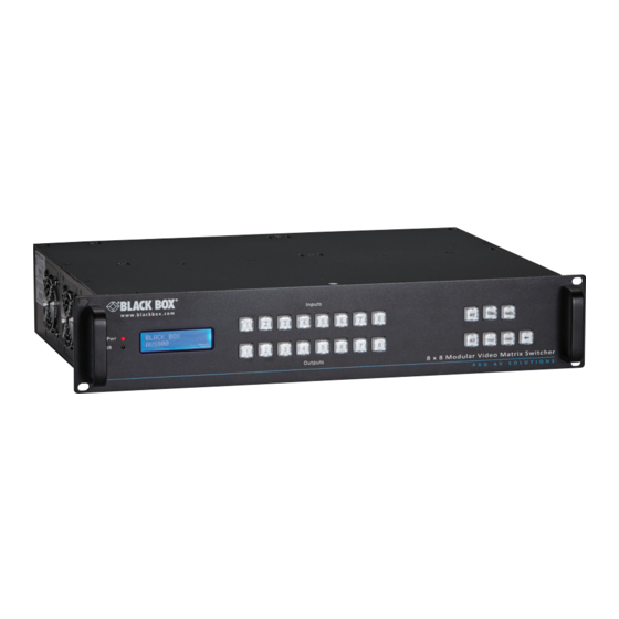
- Page 1 AVS800 Modular Video Matrix Switcher - 8 x 8 User Manual Switch eight inputs to eight outputs in any combination. Order toll-free in the U.S. or for FREE 24/7 technical support: Call 877-877-BBOX Contact (outside U.S. call 724-746-5500) Information www.blackbox.com • info@blackbox.com...
- Page 2 Trademarks Used in this Manual Trademarks Used in this Manual Black Box and the Double Diamond logo are registered trademarks of BB Technologies, Inc. Blu-ray is a trademark of the Blu-ray Disc Association. Any other trademarks mentioned in this manual are acknowledged to be the property of the trademark owners.
- Page 3 FCC and IC RFI Statements/ FEDERAL COMMUNICATIONS COMMISSION AND INDUSTRY CANADA RADIO FREQUENCY INTERFERENCE STATEMENTS Class B Digital Device. This equipment has been tested and found to comply with the limits for a Class B computing device pursuant to Part 15 of the FCC Rules. These limits are designed to provide reasonable protection against harmful interference in a residential installation.
- Page 4 NOM Statement Normas Oficiales Mexicanas (NOM) Electrical Safety Statement INSTRUCCIONES DE SEGURIDAD 1. Todas las instrucciones de seguridad y operación deberán ser leídas antes de que el aparato eléctrico sea operado. 2. Las instrucciones de seguridad y operación deberán ser guardadas para referencia futura.
- Page 5 NOM Statement 12. Precaución debe ser tomada de tal manera que la tierra fisica y la polarización del equipo no sea eliminada. 13. Los cables de la fuente de poder deben ser guiados de tal manera que no sean pisados ni pellizcados por objetos colocados sobre o contra ellos, poniendo particular atención a los contactos y receptáculos donde salen del aparato.
- Page 6 Safety Precautions Safety Precautions To ensure the best operation from the product, read all instructions carefully before using the device. Save this manual for further reference. • Unpack the equipment carefully and save the original box and packing material for possible future shipment.
-
Page 7: Table Of Contents
Table of Contents Table of Contents Specifications ....................8 1.1 Main Unit ....................8 1.2 Changeable Cards ..................9 1.2.1 AVS-4I-DVI and AVS-4O-DVI ............9 1.2.2 AVS-4I-UNI ...................10 1.2.3 AVS-4I-VGA and AVS-4O-VGA ............11 1.2.4 AVS-4I-HDM and AVS-4O-HDM ..........12 1.2.5 AVS-4I-HDB and AVS-4O-HDB ............13 1.2.6 Stereo Audio Card (Pre-Installed) ..........14 Overview .....................15 2.1 Introduction ...................15... -
Page 8: Specifications
Chapter 1: Specifications 1. Specifications 1.1 Main Unit Specifications Table 1-1. Main Unit specifications. Hardware User Controls Front-panel buttons Connectors Serial control port: RS-232 DB9 female DCE connector, Pin 2 = TX, Pin 3 = RX, Pin 5 = GND; Audio: Input: (8) 3.5-mm captive screw connectors 5-pole stereo, Output: (8) 3.5-mm captive screw connectors 5-pole stereo... -
Page 9: Changeable Cards
Chapter 1: Specifications 1.2 Changeable Cards 1.2.1 AVS-4I-DVI and AVS-40-DVI Table 1-2. AVS-4I-DVI and AVS-4O-DVI specifications. Input Connector (4) female DVI Input Level TMDS 2.9–3.3 V Input Impedance 75 ohms Output Connector (4) female DVI Output Level TMDS 2.9–3.3 V Output Impedance 75 ohms General... -
Page 10: Avs-4I-Uni
Chapter 1: Specifications 1.2.2 AVS-4I-UNI Table 1-3. AVS-4I-UNI specifications. Input Connector (4) female DVI Input Level TMDS 2.9–3.3 V Input Impedance 75 ohms General Gain 0 dB Bandwidth 340 MHz (10.2 Gbps) Video Signal DVI, HDMI, VGA, Composite, YPbPr Switching speed 200 ns (max.) Max. -
Page 11: Avs-4I-Vga And Avs-4O-Vga
Chapter 1: Specifications 1.2.3 AVS-4I-VGA and AVS-4O-VGA Table 1-4. AVS-4I-VGA and AVS-4O-VGA specifications. Video Input Connector (4) HD 15-pin female VGA Input Level 0.5–2.0 Vp-p Input Impedance 75 ohms Audio Input Connector (4) stereo audio, 3-pin terminal block CMRR >90 dB @ 20 Hz – 20 kHz Input impedance >10 K Video Output... -
Page 12: Avs-4I-Hdm And Avs-4O-Hdm
Chapter 1: Specifications 1.2.4 AVS-4I-HDM and AVS-4O-HDM Table 1-5. AVS-4I-HDM and AVS-4O-HDM specifications. Video Input Connectors (4) HDMI female Input Level TMDS 2.9–3.3 V Input Impedance 100Ωohms (differential) Audio Input Connectors (4) analog 3-pin pluggable terminal blocks Input impedance 75 ohms Frequency response 20 Hz –... -
Page 13: Avs-4I-Hdb And Avs-4O-Hdb
Chapter 1: Specifications Table 1-5 (continued). AVS-4I-HDM and AVS-4O-HDM specifications. General (continued) Supported Embedded HDMI audio: PCM, Dolby Digital, DTS, DTS-HD; audio format Analog audio: PCM EDID and HDCP Compliant with HDCP 1.4; supports manual EDID management management 1.2.5 AVS-4I-HDB and AVS-4O-HDB Table 1-6. -
Page 14: Stereo Audio Card (Pre-Installed)
Chapter 1: Specifications Table 1-6 (continued). AVS-4I-HDB and AVS-4O-HDB specifications. Crosstalk < -50 dB @ 5 MHz Max. Resolution 4K x 2K Transmission 1080p < or = 70 m; Distance 4K x 2K < or = 40 m Switching speed 200 ns (max.) >70 dB @ 100 MHz - 100 M Return loss... -
Page 15: Overview
RS-232 port for serial control and an optional IP port for TCP/IP control. It can be easily controlled by third-party devices. With its flexible design, AVS800 can be used for different projects and is all-in-one solution. Applications include multimedia conference rooms, control rooms, broadcasting rooms, shopping centers, etc. -
Page 16: Signal Cards (Changeable Cards)
• IR remote (cell battery not included) • (4) plastic cushions • RS-232 cable This user manual/installation guide can be downloaded from the Black Box Web site. To download from the Web site: 1. Go to www.blackbox.com 2. Enter the part number (AVS800) in the search box: 3. -
Page 17: Hardware Description
Chapter 2: Overview If you have any trouble accessing the Black Box site to download the manual, contact our Technical Support at 724-746-5500 or info@blackbox.com. 2.5 Hardware Description 2.5.1 Front and Back Panels Figure 2-1. Front panel of the AVS800. - Page 18 GND connector Used for system grounding. NOTE: There are only two input and two output slots for the main unit, so you can only install two input and two output cards on the AVS800. The input/output cards can be hot-swapped.
-
Page 19: Cards
Chapter 2: Overview 2.5.2 Changeable Cards The AVS800 supports expansion via various changeable input/output cards that use different signals including DVI, HDMI, VGA, twisted-pair, etc. AVS-4I-DVI and AVS-4O-DVI DVI signal cards. (See the specifications in Chapter 1.) These cards are compatible with HDMI1.3 and HDCP, but do not support analog signals. -
Page 20: Avs-4I-Uni
Chapter 2: Overview Table 2-3. DVI-I connector pinout. Pin Function Function TMDS Data 2- TMDS Data 3+ TMDS Data 2+ +5V Power TMDS Data 2/4 Shield 15 Ground (return for +5 V, Hsync and Vsync) TMDS Data 4- Hot-plug detect TMDS Data 4+ TMDS Data 0- DDC Clock... -
Page 21: Avs-4I-Vga And Avs-4O-Vga
Chapter 2: Overview AVS-4I-VGA and AVS-4O-VGA VGA signal card. (See the specifications in Chapter 1.) Scale all inputs to 1080p. Compatible with Composite, YUV, YC (Factory preset function), the card supports RGBHV, RGsB, RGBS, RsGsBs, YUV, YC, and Composite video. AVS-4I-VGA: input card with a maximum of four VGA inputs and four stereo audio inputs. - Page 22 Chapter 2: Overview Table 2-4. VGA connector pinout. Function Function KEY/PWR GREEN BLUE ID0/RES ID2/RES ID1/SDA HSync RED_RTN VSync GREEN_RTN ID3/SCL BLUE_RTN — — Connect the devices via VGA-to-Component or VGA- to-Composite cable as shown below: Figure 2-9. Connect with Component Video (YPbPr) Source Composite Figure 2-10.
-
Page 23: Avs-4I-Hdm And Avs-4O-Hdm
Chapter 2: Overview AVS-4I-HDM and AVS-4O-HDM 4K HDMI signal card. (See the specifications in Chapter 1.) The card supports hot-plug, complies with HDMI 1.4 and HDCP 1.4 standards, is compatible with a DVI signal, supports a high-definition HDMI source up to 4K x 2K, complies with the 1080p 3D standard, and provides an auxiliary audio port as a supplement to HDMI embedded audio. -
Page 24: Avs-4I-Hdb And Avs-4O-Hdb
Chapter 2: Overview Table 2-5. HDMI connector pinout. Pin Function Function TMDS Data 2- TMDS Clock Shield TMDS Data 2 Shield TMDS Clock- TMDS Data 2- TMDS Data 1+ Not connected TMDS Data 1 Shield DDC Clock TMDS Data 1- DDC Data TMDS Data 0+ Ground... - Page 25 Chapter 2: Overview Figure 2-15. AVS-4O-HDB card. Figure 2-16. Cable pinout diagram. NOTE: Cable connectors must be metal, and the shielded layer must be connected to the connector's metal shell to ground the cable. Table 2-6. TIA pinouts. TIA/EIA 568A connector pinout. TIA/EIA 568B connector pinout.
-
Page 26: Stereo Audio Card (Pre-Installed)
Chapter 2: Overview Stereo Audio Card (Pre-Installed) The 8x8 stereo audio crosspoint switching card supports balanced/unbalanced audio via a different connection. It cannot be hot-plugged—you must power off the unit to install the card in the chassis. Figure 2-17. Audio card. Figure 2-18. -
Page 27: System Connection
2. Make sure that all of the power switches, plugs, sockets, and power cords are insulated and safe. 3. Connect all devices before power on. 3.2 Connection Diagram RS-232 control panel HDTV AVS800 AVS-HDB-RX IR receiver AVS-HDB-TX Speakers Blu-ray Figure 3-1. System diagram. -
Page 28: Applications
Chapter 3: System Connection 3.3 Applications Applications for the switch include radio and television, multimedia meeting rooms, big screen displays, education, and command and control centers. Page 28 877-877-2269 | blackbox.com... -
Page 29: Control Operations
Chapter 4: Control Operations 4. Control Operations 4.1 Front Panel Button Control Users can control the AVS800 rapidly and directly with its front-panel buttons. Here is a brief operation guide to front panel buttons. Format: “Input Channel” + “Switch Mode” +“Output Channel”... -
Page 30: Ir Remote Control
Chapter 4: Control Operations 4.2. IR Remote Control Using the IR remote, you can control the AVS800 remotely. The function buttons on the IR remote are the same with the ones on the front panel, and the IR remote shares the same operations and commands as the control panel. -
Page 31: Rs-232 Control
4.3. RS-232 Control 4.3.1 Connecting the RS-232 Communication Port Instead of the front control panel and IR remote, the AVS800 can be controlled by a far-end control system or through the Ethernet via the RS-232 communication port. This RS-232 communication port is a female DB9 DCE connector. Its pin layout is shown in the table below. - Page 32 Chapter 4: Control Operations Table 4-2. Commands for the main unit. Command Description /*Type; Ask for the model’s information. /%Lock; Lock the keyboard of the control panel on the Matrix. /%Unlock; Unlock the keyboard of the control panel on the Matrix. /^Version;...
- Page 33 Chapter 4: Control Operations Table 4-2 (continued). Commands for the main unit. Command Description PWON. Work normally. PWOFF. Enter in standby mode. /V00. Ask for the version of backboard software. UpgradeIntEDID[x]. Upgrade built-in EDID data. Supports 6 types of EDID data (see Note 6).
- Page 34 Chapter 4: Control Operations Table 4-3. Commands for Signal Cards. Command Description AVS-4I-VGA Card USER/I/[x]:0622%; Set the signal of input channel [x] to VGA. USER/I/[x]:0623%; Set the signal of the input channel [x] to YCBCR. USER/I/[x]:0624%; Set the signal of input channel [x] to SVIDEO. USER/I/[x]:0625%;...
- Page 35 Chapter 4: Control Operations Table 4-3 (continued). Commands for Signal Cards. Command Description AVS-4I-UNI Card (continued) USER/I/[x]:0628%; Set the resolution of input [x] to 1280x800, WXGA USER/I/[x]:0629%; Set the resolution of input [x] to 1920x1080, 1080P USER/I/[x]:0620%; Set the resolution of input [x] to 1920x1200, WUXGA USER/I/[x]:0621%;...
- Page 36 4. Type the command carefully, it is case-sensitive. 5. Commands pertaining to EDID are only available for signal cards that support EDID management. 6. AVS800 features six built-in EDID data channels. The chart below illustrates detailed information. Table 4-4. EDID data.
- Page 37 Chapter 4: Control Operations 5. Switch on the detailed feedback command from the COM port: /:MessageOn; It will show the detailed switch information when it switches. Example: when switch 1->2, the feedback will be “AV01 to 02”. 6. Transfer signals from an input channel to corresponding output channel: [x]#. Example: “5#.”...
-
Page 38: Tcp/Ip Control
4001. IP and Gateway can be changed as needed; Serial Port cannot be changed. Controlled by Single PC Connect a computer to the Ethernet port of the AVS800, and set its IP address and gateway to the same IP range as the default IP of the AVS800 (192.168.0.178). -
Page 39: Tcp/Ip Settings
Step 1. Connect the TCP/IP port of the AVS800 to an Ethernet port of a PC with twisted-pair cable. Step 2. Set the PC’s IP address and gateway to be in the same IP range as the AVS800. Remember the PC‘s original IP address and gateway. - Page 40 Set the port number to 4001 (unique, other numbers are unavailable). c. Press the Apply button on the present page to save your settings. Step 6. Select the “Reset Device” tab and your settings will be loaded to the AVS800. Page 40...
-
Page 41: Troubleshooting
Failed or loose Make sure the connection is good. connection Contact Black Box Technical Support The switcher is broken at 724-746-5500 or info@blackbox.com. IR remote does Run out of battery Change the battery. - Page 42 Cannot control the Wrong RS-232 commu- Type in correct RS-232 device by control nication parameters communication parameters. device (e.g. a PC) Contact Black Box Technical Support through RS-232 Broken RS-232 port at 724-746-5500 or info@blackbox. port com. Cannot control the...
- Page 43 NOTES Page 43 877-877-2269 | blackbox.com...
- Page 44 724-746-5500 or blackbox.com. About Black Box Black Box provides an extensive range of networking and infrastructure products. You’ll find everything from cabinets and racks and power and surge protection products to media converters and Ethernet switches all supported by free, live 24/7 Tech support available in 60 seconds or less.
Need help?
Do you have a question about the AVS800 and is the answer not in the manual?
Questions and answers