Table of Contents
Advertisement
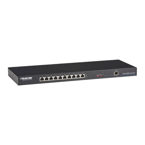
DCX3000 Switch
Share multiple computers with numerous users via
standard structured cabling.
Order toll-free in the U.S.: Call 877-877-BBOX (outside U.S. call 724-746-5500)
Customer
FREE technical support 24 hours a day, 7 days a week: Call 724-746-5500 or fax 724-746-0746
Support
www.blackbox.com • info@blackbox.com
Information
DCX3000
Advertisement
Table of Contents

Subscribe to Our Youtube Channel
Related Manuals for Black Box DCX3000


Summary of Contents for Black Box DCX3000
- Page 1 DCX3000 DCX3000 Switch Share multiple computers with numerous users via standard structured cabling. Order toll-free in the U.S.: Call 877-877-BBOX (outside U.S. call 724-746-5500) Customer FREE technical support 24 hours a day, 7 days a week: Call 724-746-5500 or fax 724-746-0746 Support www.blackbox.com •...
- Page 2 DCX3000 Switch Trademarks Used in this Manual Black Box and the Double Diamond logo are registered trademarks, and ServSwitch is a trademark, of BB Technologies, Inc. Mac is a registered trademark of Apple Computer, Inc. Linux is registered trademark of Linus Torvalds.
- Page 3 FCC and IC RFI Statements Federal Communications Commission and Industry Canada Radio Frequency Interference Statements This equipment generates, uses, and can radiate radio-frequency energy, and if not installed and used properly, that is, in strict accordance with the manufacturer’s instructions, may cause inter ference to radio communication. It has been tested and found to comply with the limits for a Class A computing device in accordance with the specifications in Subpart B of Part 15 of FCC rules, which are designed to provide reasonable protection against such interference when the equipment is operated in a commercial environment.
-
Page 4: Instrucciones De Seguridad
DCX3000 Switch Instrucciones de Seguridad (Normas Oficiales Mexicanas Electrical Safety Statement) 1. Todas las instrucciones de seguridad y operación deberán ser leídas antes de que el aparato eléctrico sea operado. 2. Las instrucciones de seguridad y operación deberán ser guardadas para referencia futura. -
Page 5: Table Of Contents
Table of Contents Contents 1. Specifications ....................................6 2. Welcome ....................................7 2.1 Access permissions ................................7 2.2 Port designations ................................8 3. Installation ....................................9 3.1 Connections ..................................9 3.1.1 Computer connections: Video ..........................9 3.1.2 Computer connections: USB ..........................10 3.1.3 Computer connections: Data link ........................ -
Page 6: Specifications
DCX3000 Switch 1. Specifications Approvals: CE, FCC Hardware Compatibility: All computers with DVI-D/DisplayPort digital video and USB interfaces Software Compatibility: Operates with all known software and operating systems including Windows , Linux , Unix , BSD, all Sun OS, all Mac OS, NetWare , etc. -
Page 7: Welcome
2.1 Access permissions The DCX3000 Switch uses a system of hierarchal Access permissions to mediate between numerous consoles and multiple com- puters. Each console is granted the use of up to four types of access permissions to each computer, most of which influence how other users can gain simultaneous access to the same computer. -
Page 8: Port Designations
2.2 Port designations By default the DCX3000 Switch provides 10 user console ports on its front panel and 20 computer ports along its rear panel, however, these designations are not fixed. If your installation requires a greater number of computers or has a need for more user... -
Page 9: Installation
• If used, position the DCX3000 Switch in a central position that serves the host systems and user modules without exceeding the maximum link lengths. It will also require a source of mains power. • Situate each DCX3000 Remote module close to the peripherals to which it will be connected and near to a source of mains power. -
Page 10: Computer Connections: Usb
Each DCX3000 SAM module requires a single USB connection to the computer. This provides essential power for the DCX3000 SAM module in addition to the USB signals. Each DCX3000 Remote module acts as a USB 2.0 hub and thus provides four sockets for peripherals. -
Page 11: Switch Connections: Computer Links
3.1.4 Switch connections: Computer links When a DCX3000 Switch is used, it sits as the central matrix between the various host computers and the users. The host com- puter links are generally made via the sockets at the rear of the switch, although some host links can also be supported from the sockets on the front panel (see below). -
Page 12: Switch Connections: Network Link
All system configuration is carried out via an Ethernet link, allowing adjustments to be made by authorized admin users located next to the DCX3000 unit, or anywhere. The auto-sensing network port can determine between 10, 100Mbps or 1Gbps links and can also adjust to straight or cross-over cables. -
Page 13: Switch Connections: Power
3.1.9 Switch connections: Power Each DCX3000 Switch is supplied with a single power adapter but offers the facility to use a second input in order to provide operational redundancy. The DCX3000 unit can operate perfectly well from a single power adapter operating alone. When two adapters are connected, the unit will spread its load between them;... -
Page 14: Console Connections: Video
1920 x 1200 at 60Hz - aka ‘WUXGA’). If a second display is required to support a dual video installation, use another DCX3000 Remote module to drive the second dis- play, and combine the two user modules into a single Console within the DCX Matrix configuration application. -
Page 15: Console Connections: Usb
3.1.11 Console connections: USB The DCX3000 Remote module contains a USB hub that can support up to four v1.1 or v2.0 USB devices (in any combination). All four USB sockets, two on the front panel and two on the rear, are identical in operation. -
Page 16: Console Connections: Data Link
DCX3000 Switch 3.1.13 Console connections: Data link Each DCX3000 Remote module is linked via a CATx cable either to a central DCX3000 Switch module (multi-system matrix instal- lation) or directly to a DCX3000 SAM module (single system installation). For best results use CAT7 cables to link all DCX3000 SAM modules - do not exceed 50 meters (164 feet). -
Page 17: Console Connections: Power
3.1.15 Console connections: Power There is no on/off switch on the DCX3000 Remote module, so operation begins as soon as power is applied. The supplied power adapter uses a locking-type plug to help prevent accidental disconnections; please follow the instructions given right whenever disconnecting a power adapter. -
Page 18: Configuration
This secure, password protected application is accessible by any authorized admin user, located anywhere. 4.1.1 To access DCX Matrix 1 Use a computer that is directly or indirectly (i.e. via a network switch) connected to the DCX3000 Switch. If you need to make a temporary connection, see below. - Page 19 1 If you need to make a temporary connection for configuration purposes, use a standard patch cable (cross-over or straight connections are both supported) to link the Ethernet 10/100 network port ( ) on the front panel of the DCX3000 Switch to your computer’s network port. 724-746-5500 | blackbox.com...
-
Page 20: Using Dcx Matrix
DCX3000 Switch 4.2 Using DCX Matrix 4.2.1 The Dashboard page Once you have successfully logged in, DCX Matrix will show the dashboard page to provide a general overview of your DCX installation. You can also re-display this page by clicking the Dashboard entry in the menu:... -
Page 21: Quick Guide To Creating A New Installation
• Add the required consoles (either before or after they are connected) Configure > Consoles By default the DCX3000 Switch provides 20 computer ports along its rear panel and 10 user ports along its front panel. If necessary, these standard arrangements can be changed to suit your... -
Page 22: The Control Page
DCX3000 Switch 4.4 The Control page The Control page provides a Connection map that allows the admin user to view and affect how con- soles are connected to the various computers. This page is particularly useful when managing video-only installations. -
Page 23: The Configure
- settings related to the DCX3000 SAM modules and their host computers. 4.5.1 Central Switch > General Basic descriptive settings for the DCX3000 Switch. These are most useful when multiple DCX installations are being managed and labelling each installation as you go, is a good habit to get into: •... - Page 24 DCX3000 Switch 4.5.2 Central Switch > Network All of the key settings for the network capabilities of the DCX3000 Switch are here: • DHCP - allows you to choose to use DHCP (Dynamic Host Configuration Protocol) to automatically determine all network settings or set them manually.
- Page 25 System EDID’ from the list of fixed and user EDIDs. • Originating Port - indicates which switch port supplied each user EDID. Note: The DCX3000 Switch will modify the EDID, if a Dual link monitor is connected, to list only the video resolutions that it is capable of supporting.
-
Page 26: Configure > Consoles
DCX3000 Switch 4.6 Configure > Consoles A Console is a collective term for a set of peripheral devices arranged around one or more DCX3000 Remote modules. This page lists all registered consoles alphabetically by their Names: Add new Click to add a new console. - Page 27 • Ports - add the user port number (located on the main switch) used by the DCX3000 Remote module associated with this console. For multi- head consoles, ensure that the port used by the primary DCX3000 Remote module (the one that has the primary display and peripherals attached) is the first one in the list.
-
Page 28: Configure > Consoles > Receivers
Click to view receiver details. Listed in order of the DCX3000 Switch port to which they are attached, this page shows various details for each DCX3000 Remote module: • Firmware - the current internal software version for each DCX3000 Remote module. - Page 29 Chapter 4: Configuration 4.7.1 View receiver details Click a receiver entry to view the configuration details of the DCX3000 Switch port to which it is connected. Within this page it is possible to reboot and/or recover a receiver. 4.7.1.1 Recovering a receiver This option (shown only when the Maintenance >...
-
Page 30: Configure > Computers
DCX3000 Switch 4.8 Configure > Computers This page lists the computer systems that are connected to the DCX3000 Switch unit via individual DCX3000 SAM modules: Add new Click to add a new comput- er. See oppo- site. In addition to the Name and Description, the columns also provide the following useful details for each computer entry: •... - Page 31 • Description - a further opportunity to add more information about the computer. • Ports - Add one or more port numbers used by the DCX3000 SAM module(s) associated with this computer. 4.8.2 Configure > Computers > Edit an entry This page allows you to edit the configuration details for a chosen computer.
-
Page 32: Configure > Computers > Transmitters
DCX3000 Switch 4.9 Configure > Computers > Transmitters Each computer connects to a DCX3000 SAM transmitter module. This page lists each DCX3000 SAM module and their key details: View details See opposite. Listed in order of the DCX3000 Switch port to which they are attached, this page shows various details for each DCX3000 SAM module: •... - Page 33 Chapter 4: Configuration 4.9.1 View transmitter details Click a transmitter entry to view the configuration details of the DCX3000 Switch port to which it is connected. Within this page it is possible to reboot and/or recover a transmitter. 4.9.1.1 Applying a different EDID...
-
Page 34: Reallocating Ports
4.10 Reallocating ports By default the DCX3000 Switch provides 20 computer ports along its rear panel and 10 user console ports along its front panel. If your installation has a greater number of computers or a need for more user consoles, you can alter the allocation of these stan- dard ports: •... -
Page 35: The Users Page
Chapter 4: Configuration 4.11 The Users page This page lists all registered users and allows the admin user to add, edit and delete entries, as required. Note: When changes are made to user details, you are recommended to make a backup file. Change password Edit Add new... -
Page 36: The Maintenance
These items are only shown when Settings > Advanced Mode On is chosen. This section indicates the current temperature readings within the DCX3000 Switch for the following: • The processor core, • The internal case area, • The main circuit board,... - Page 37 Confirmation is required once this clicked. modules. Confirmation is button is clicked. required once this button is Note: Be sure that the DCX3000 Switch has clicked. the latest firmware installed before using this option. Backup Restore...
- Page 38 DCX3000 Switch 4.12.3 Maintenance > Settings This page provides options related to the user interface. When you make a change, you need to click the Update button to save it. Web UI Mode When this option is set to Advanced, extra details are shown on certain pages, such as: •...
-
Page 39: Resetting And Recovering
4.13 Resetting and recovering There may be rare occasions when the main switch or a module needs to be given a hard reset. The DCX3000 Switch and DCX3000 Remote module both have concealed reset buttons for this purpose. You need to use a narrow implement (e.g. a straightened-out paper clip) to press-and-hold the recessed reset button on the front panel: 4.13.1 DCX3000 Switch... - Page 40 4.13.2.1 DCX3000 Remote module > Boot into recovery mode This procedure may be necessary if an attempted firmware upgrade has failed. For such a situation the DCX3000 Remote module always retains a recovery image that will return the unit to a working condition, prior to reattempting a firmware upgrade.
-
Page 41: Operation
Chapter 5: Operation 5. Operation The DCX system is designed to be transparent in operation. A simple OSD (On Screen Display) interface allows each user to view and select from the available host computers. 5.1 Viewing the OSD 5.1.1 To view the matrix 1 From a console keyboard, press CTRL + ALT + M to display the matrix: The outputs of the available host computers will be displayed within live thumbnail images. -
Page 42: Indicators
DCX3000 Switch 5.3 Indicators The DCX3000 Switches, the DCX3000 SAM and DCX3000 Remote modules contain various indicators to provide you with status information. 5.3.1 DCX3000 Switch - Red front panel status indicators The red status indicators on DCX3000 Switch front panels provide various key power and operation feedback:... - Page 43 Switch or directly, in a simple extender installation 5.3.5 DCX3000 SAM module - Green and amber status indicators The green and amber indicators on the link port of each DCX3000 SAM (computer) module provide the following status information: Special condition Amber...
-
Page 44: Appendix A. Safety Information
DCX3000 Switch Appendix A. Safety Information • For use in dry, oil free indoor environments only. • Do not use to link between buildings. • Ensure that the twisted pair interconnect cable is installed in compliance with all applicable wiring regulations. - Page 45 About Black Box Black Box Network Services is your source for an extensive range of networking and infrastructure products. You’ll find everything from cabinets and racks and power and surge protection products to media converters and Ethernet switches all supported by free, live 24/7 Tech support available in 60 seconds or less.
Need help?
Do you have a question about the DCX3000 and is the answer not in the manual?
Questions and answers