
Related Manuals for Zonestar P802QS


Summary of Contents for Zonestar P802QS
- Page 1 Installation Guide Model:P802QS/P802QSU/P802QR2/P802QM2/M8S/M8R2 Ver 4.2 www.zonestar3d.com Youtube Channle Facebook Group...
- Page 2 Version Record Version Date Author Check Remark V1.0 2016-07-20 Chris Hally 1st Version New package and upgrade V2.0 2017-05-10 Alien Hally V3.0 2017-06-07 Alien Hally Modify “wiring” V4.0 2018-03-24 Hally Combine P802Q(M8) serial installation guide V4.2 2018-06-20 Hally Fix some bugs If you have any problems with the installation, please feel free to contact us, we will reply to you ASAP! Email:...
- Page 3 What's different in the different model P802Q series is ZONESTAR‘s most popular Prusa i3 type product after the P802M and P802N series. According to the frame material and the number of extruders, we divide the products into different models. The differences between...
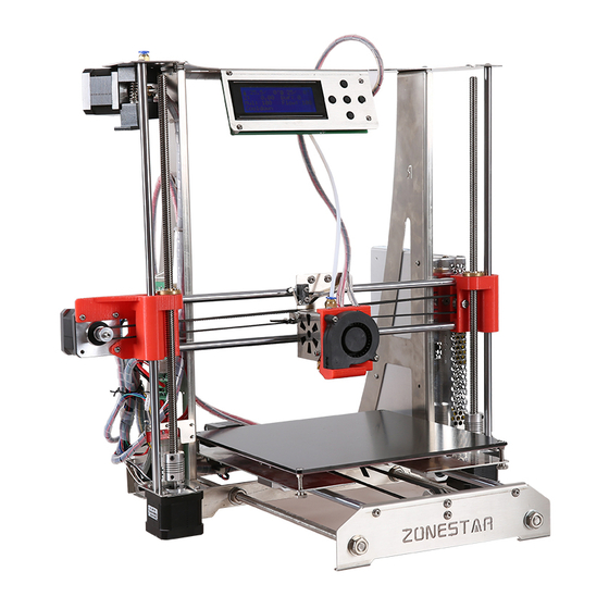
- Page 4 Product proview LCD and Keypad* * Used knob keypad in the different machine model / versions Proximity sensor(for bed auto leveling) X-Motor Z Endstop Power Supply (PSU) Extruder Fan Hotend HotBed Z-Motor(right)
- Page 5 Product proview Extruder Extruder engine #1 engine #2 Z-Motor(left) Y ENDSTOP Y Motor Control Board...
- Page 6 Parts: Metal pieces Hotend housing Print head bracket Y Motor Bracket Hed Bed bracket Part Number: ZSD-12 Part Number: ZSD-14-V2 Part Number: P802Q-YM Part Number: 220x220-Bed Pre-assemled hotend base frame top base frame left base frame right base frame back Part Number: P802Q-LMT Part Number: P802Q-L Part Number: P802Q-R...
- Page 7 Parts: package A4 parcel are spare part. A5 package is optional for different model.
- Page 8 Parts: screws and nuts PM3x6 Screw (x45) PM4x6 Screw (x45) M3 Nut (x10 ) KM3x25 Screw (x4) M3x12 pole (x4) PM3X20 Screw(x5) Φ4.5*22 spring (x4) M3 shim (x12) M3 Hand Nut (x4)
- Page 9 Viode turorial Assemble Guide Electronic Parts P802QR2 Wiring Guide Assemble Guide Check Note 1: The video tutorial may be a little different from your kit! Note 2: We suggest you check the electronic parts before installed.
- Page 10 Assemble Y-axis belt pulley (Pre-assembled) shim 5x22x1.2 *3 shim 5x12x0.6 *2 ball bearing 625zz M5x14 Note:smooth surface of the shims towards ball bearings.
- Page 11 Assemble LCD display module (Pre-assembled) pole M3x8 LCD 2004 keypad pole M3x8 PM3x10 pole M3x12 pole PM3x10 M3x12 M3x6...
- Page 12 Assemble slider module left (Pre-assembled) 1. Put two linear bearings on slider module left, through the two bearings by sliding rod, then push bearings into slot, check concentricity of the bearings. 2. Mount copper nut,lock with three M3x20 screws and M3 nuts. M3x20 *3 copper nut slider module left...
- Page 13 Assemble slider module right (Pre-assembled) 1.mount screw M5x25,shim M5, linear bearing shim M5,lock with nut M5. 2.mount copper nut, lock with three screws M3. M3x20 *3 copper nut slider M5x20 module right shim M5 *3 M3 Nut *3 ball bearing 625zz...
- Page 14 Assemble hotend (Pre-assembled except proximity sensor) Hotend housing PN: ZSD-12 PTFE Fitting X ENDSTOP PM3x6 *2 SCS8UU bearing PM2.5x8 PA3x14 *4 Heat sink 4010 FAN PM3x16 *2 PM4x6 *6 Print head bracket Heat block Fan housing PN: ZSD-14-V2 PM3x20 *2 PM3x6 *3 PM3x10 *2 Proximity sensor...
- Page 15 Assemble extrude engine (Pre-assembled) PM3x10 PM3x6 block knob Jbckscrew *2 Shim 8x4 *2 Install the U-bearing fitting to this part M4x10...
- Page 16 Assemble extruder engine (2 sets for dual extruder) Lock the jbckscrews Motor Shaft length: 16mm HM5x10 PM3x20 *2 String Note: One of jbckscrew should be locked on the flat surface Note: This hole should at the center of the gear Press the thumb and then load...
- Page 17 Install X-axis Motor to slider left 1. Install a motor (shaft length is 23mm) to silder left , lock with 3 pcs M3x6 screws. 2. Install one pulley to the stepper motor, lock the jbckscrew on the pulley. silder left PM3x6 *3 Note: Please pay attention to the installation direction of the...
- Page 18 Assemble heat bed bracket Install 4 bearings (SCS8UU) on heat bed bracket, lock with M4x6mm screws. PM4x6 *12 Hed Bed bracket PN: 220x220-Bed SCS8UU linear bearing *4 Note: In order to let the bearin is on the same line, please insert a lead rod to the linear bearing before tightend the M4 screws.
- Page 19 Assemble base frame front Y-axis belt pulley base frame front PN: P802Q-YF PM4x6 *2...
- Page 20 Assemble base frame back Note 1: Y Endstop install on the down of the metal frame PM3x20 *2 Base frame Note 2: Install the motor to the back lowest position. PM4x6 *2 base frame back PN: P802Q-YB Y-axis limit M3 nut *2 switch M3 shim *3 Note 3: lock the jbckscrew on...
- Page 21 Assemble base frame bottom base frame bottom PN: P802Q-LMB PM3x6 *8 Coupling 5x8 *2 shim *8 shaft length is 23mm Connector toward back Note 1: Don’t tighten the motor in this step. Note 2: Don’t lock the jbckscrew on the coupling in this step.
- Page 22 Assemble base frame left and right base frame left PN: P802Q-L base frame right PN: P802Q-R base frame bottom PM4x6 *4 Notice: base frame left and base frame right are different!
- Page 23 Assemble base frame back PM4x6 *4 base frame back...
- Page 24 Install LCD display module base frame top PN: P802Q-LMT LCD display module PM3x6 *4...
- Page 25 Install base frame top PM4x6 *4 base frame top base frame right...
- Page 26 Assemble Y-axis bracing pieces PM4x6 *6 bracing piece *2 PN: P802Q-YI...
- Page 27 Install Y-axis sliding rod and heat bed bracket NOTE Please insert slowly and carefully, prevent to damage the linear bearings!! Lead rod M8x380mm *2 PS: Using the lead rod with hole in the end. heat bed bracket M4x6 *4...
- Page 28 Install Y-axis timing belt tie-wrap *2 timing belt Note: Tighten the belt before locked it.
- Page 29 Assemble Heat Bed MK3 heat bed M3 nut *4 KM3x25 *4 Note: Don’t tighten the screw in this step.
- Page 30 Install Heat Bed Note: Wires toward back. After the installation is completed, the wires should be wrapped with a wrapping tape. MK3 Heat Bed Spring *4 Hand nut *4...
- Page 31 Install Z-endstop 1. Assemble the Z ENDSTOP to the Z endstop frame with 2 pcs M3x6 screws. 2. Install the Z ENDSTOP module to base frame left Z endstop PM3x6 *2 PM3x6 *2 Back view NOTE: Before installing Z ENDSTOP, Please cut off excess pins and attach stickers to prevent short circuits.
- Page 32 Install slider module left and rods 1. Through base frame top and Lead screw 345mm Lead screw fix module and slider module left by lead rod, PA3x10 *2 its bottom entering the hole on Z-axis motor(left),its top PM4x6 locked with M4x6. Lead screw fix 2.
- Page 33 Install slider module right and rods 1. Through base frame top and Lead screw 345mm Lead screw fix module and slider module right by lead PA3x10 *2 rod, its bottom entering the hole on Z-axis motor(left),its PM4x6 top locked with M4x6. Lead screw fix module 2.
- Page 34 Debug Z-axis driver system Tips: As far as possible to keep the motor shaft and Z axis lead screw are in the center of the coupling.
- Page 35 Install hotend Through hole of slider module right and hole of extruder and hole of slider module left,its right end leveled with hole edge of slider module right. slider module left slider module right Hotend sliding rod 380mm(without hole) x2 NOTE Please insert slowly and carefully,...
- Page 36 Install X-axis timing belt Fixed one end of the timing belt on one clasp of the hotend by cable tie, through pulley of slider module left and ball bearing of slider module right,then fixed on the other clasp of the hotend by tie-wrap. clasp tie-wrap *2 timing...
- Page 37 Install AC power connector Base Frame right AC Power Connector...
- Page 38 Install power supply Install 4 pcs isolation pole to power supply before intall the power supply to metla power supply frame M3x6 *3 M3x5+6 Nylon screw base frame right...
- Page 39 Install control board Metal Frame left Pole M3x12 *4 Control board PM3x6 *8...
- Page 40 Install extruder engine PM3x10 *2 PM3x10 *2 base frame top Extruder engine #2 Extruder engine #1 Note: single extruder printer has only one extrude engine.
- Page 41 Install Filament feeder bracket If there is one set filament feeder in the parcel, please refer to the below picture to assemble it, otherwise please skip this step. Extruder motor Base Frame Top PM3x10 *2 Base Frame Left Feeder pipe Copper pole M3x45 Filament feeder...
- Page 42 Install Filament Run Out Detector If there are filament run out deteector in the parcel, please refer to the below picture to assemble it, otherwise please skip this step. PM3X10 *2 Scan this QR code to Filament run out detector purchase a Filament Run out Detector...
- Page 43 Install PTFE tube(2PCS for P802QR2) Push the ring on the fitting and then insert PTFE tube into fitting, to connect the extruder engine and hotend by PTFE tube. PTFE tube Fitting Extruder Motor Filament Roll Filament Run Out Detector Filament Hotend...
- Page 44 Wiring Guide Attention. Single extruder wiring diagram Dual extruder wiring diagram Dual extruder mix color wiring diagram Power Supply Wiring ZRIB Control Board Jumper and LED Motor wire and How to change the direction of stepper motor ...
- Page 45 !Attention! Take care when installation, to avoid electrical shock hazards! Once the connection is completed, please confirm again. WRONG WIRING MAY DAMAGED THE ELECTRONIC DEVICE! Some parts has lager operating current, please make sure the the wire and the terminal contact well. Please use cable tie to wrap the wires when wiring is completed..
- Page 46 Single extruder wiring diagram (ZRIB V5.x) Pay attention to the direction of the motor driver module.
- Page 47 Dual extruder wiring diagram (ZRIB V5.x) Pay attention to the direction of the motor driver module.
- Page 48 Dual extruder mix color wiring Diagram (ZRIB V5.x) Pay attention to the direction of the motor driver module.
- Page 49 ZRIB Control Board Jumper and LED (V5.x) Jumper: POW_SEL: Select the MCU power supply from USB or DC Input. We suggest to move the jumper to “USB” LEDS of Out Port: when uploading firmware. When the printer work, it must be set to “VREG”. RST_MCU: Reset the MCU from USB port, the HOST software can’t distinguish the control board firmware type if this jumper is removed, and it be use...
- Page 50 Power Supply Wiring The voltage of power supply is different depending on the country. Before wiring, please make sure this setting is right. AC power L, N, G must be correctly distinguished, or may endanger personal safety ! Attention! Note: Exposure wire is dangerous! “V-”...
- Page 51 How to change the direction of Stepper motor Exchange the sequence of the motor line, the motor direction will be reversed 1.use tweezers pull 2.pull out the wire 3. insert joint to connector out joint from connecot...
- Page 52 adjust the drive current of motor Because of the difference between the motors, the installation, add glass on the bed and other reasons, it may be necessary to adjust the driving limit current of the motor, too small driving current maybe cause lost step or abnormal noise. too small driving current maybe cause the motor and drive module overheating even damaged the drive module.
- Page 53 How to level the heat bed Refer to the below video to level the heat bed. Video Tutorial Link: https://youtu.be/QWsYR8NIGpc Bed Level Video guide...
- Page 54 How to adjust the height of the nozzles (for dual nozzles printer) You need to ensure the nozzle is in the same height ( error is less than 0.2mm) before starting to print, please refer to the below steps to adjust the height if need. 1.
- Page 55 Improve: Install filament feeder If you need to use 1KG filament roll, please print one feeder by yourself. Stl file download link: https://www.thingiverse.com/thing:2737828 You can also find more upgrade parts made by our other customers: https://www.thingiverse.com/search/page:2?q=zonestar&sa=&dwh=65ab5d5c3429f3...
- Page 56 Improve: Upgrade to dual extruder If you have bought a single extruder printer, you can easy to upgrade it to a dual extruder (dual color or mixed color) printer, please purchase from the below link: Click to Know More Scan to purchase...
- Page 57 Improve: Upgrade laser kit Click to Know More Scan to purchase!
- Page 58 Appendix : Assemble silder module slider module left linear bearing Notice:proper position that spring can produce compressive force. M3x20 X3 copper nut M3x30 M3 Nut x3 motor linear bearing spring M3x8 *3 Pole slider module right M3x20 X3 linear bearing X2 copper nut M5x20 slider module right...
Need help?
Do you have a question about the P802QS and is the answer not in the manual?
Questions and answers