Advertisement
Quick Links
Advertisement

Related Manuals for Zonestar P802QS


Summary of Contents for Zonestar P802QS
- Page 1 www.zonestar3d.com Youtube Channle Facebook Group...
- Page 2 Version Date Author Check Remark V1.0 2016-07-20 Chris Hally 1st Version V2.0 2017-05-10 Alien Hally New package and upgrade V3.0 2017-06-07 Alien Hally Modify “wiring” V4.0 2018-03-24 Hally Combine P802Q(M8) serial installation guide V5.0 2018-06-25 Hally Modify Metal Frame If you have any problems with the installation, please feel free to contact us, we will reply to you ASAP! Email: Support@zonestar3d.com...
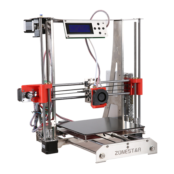
- Page 3 P802Q series is ZONESTAR‘s most popular Prusa i3 type product after the P802M and P802N series. According to the frame material and the number of extruders, we divide the products into different models. The differences between them are as follows:...
- Page 4 Product proview * Used knob keypad in the different model or versions...
- Page 5 Product proview...
- Page 6 Hotend housing Print head bracket Y Motor Bracket Hed Bed bracket Part Number: ZSD-12 Part Number: ZSD-14 Part Number: ZSD-9 Part Number: ZSD-220BED top base frame left base frame right base frame back base frame Part Number: P802Q-LMT Part Number: P802Q-L Part Number: P802Q-R Part Number: P802Q-YB front base frame...
- Page 7 PM3x6 Screw (x45) PM4x6 Screw (x45) M3 Nut (x10 ) KM3x25 Screw (x4) M3x12 pole (x4) PM3x20 Screw(x5) Φ4.5*22 spring (x4) M3 shim (x12) M3 Hand Nut (x4)
- Page 9 Z endstop...
- Page 11 1. Put two linear bearings on slider module left, through the two bearings by sliding rod, then push bearings into slot, check concentricity of the bearings. 2. Mount copper nut,lock with three M3x20 screws and M3 nuts. copper nut slider module left M3 Nut *3 LM8UU linear bearing...
- Page 12 1.mount screw M5x25,shim M5, linear bearing shim M5,lock with nut M5. 2.mount copper nut, lock with three screws M3. copper nut slider M5x20 module right shim M5 *3 M3 Nut *3 ball bearing 625zz...
- Page 13 PTFE Fitting X ENDSTOP PM3x6 *2 SCS8UU bearing PM2.5x8 PA3x12 *4 Heat sink 4010 FAN PM3x16 *2 PM4x6 *6 Print head bracket Heat block Fan housing PN: ZSD-14 PM3x20 *2 PM3x6 *3 PM3x10 *2 Proximity sensor...
- Page 14 Assemble extrude engine (Pre-assembled)
- Page 15 Assemble extruder engine (2 sets for dual extruder) Lock the jbckscrews Motor Shaft length: 16mm HM5x10 PM3x20 *2 String Note: One of jbckscrew should be locked on the flat surface Note: This hole should at the center of the gear Press the thumb and then load...
- Page 16 Install X-axis Motor to slider left 1. Install a motor (shaft length is 23mm) to silder left , lock with 3 pcs M3x6 screws. 2. Install one pulley to the stepper motor, lock the jbckscrew on the pulley. silder left PM3x6 *3...
- Page 17 Install LCD display module to top base frame Lead screw set...
- Page 18 Assemble heat bed bracket...
- Page 19 Assemble base frame front...
- Page 20 Assemble base frame back...
- Page 21 Assemble base frame bottom...
- Page 22 Assemble base frame left and right...
- Page 23 Assemble base frame back...
- Page 24 Assemble Y-axis bracing pieces...
- Page 25 Install Y-axis sliding rod and heat bed bracket NOTE Please insert slowly and carefully, prevent to damage the linear bearings!!
- Page 26 Install Y-axis timing belt Note: Tighten the belt before locked it.
- Page 27 Assemble Heat Bed...
- Page 28 Install Heat Bed...
- Page 29 Install slider modules and rods Lead rod 380mm Lead rod PS: Using 380mm the lead PS: Using rod with the lead hole on rod with the end. hole on the end. slider module left slider module right...
- Page 30 Install lead screw Lead screw 345mm Lead screw 345mm lock the jbckscrew on the coupling lock the jbckscrew on the coupling...
- Page 31 Debug Z-axis driver system Tips: As far as possible to keep the motor shaft and Z axis lead screw are in the center of the coupling.
- Page 32 Install Z-endstop Install the Z ENDSTOP module to with 2 pcs M3x6 screws. base frame left Z endstop PM3x6 *2...
- Page 33 Install hotend NOTE Please insert slowly and carefully, prevent to damage the linear bearings!!
- Page 34 Install X-axis timing belt clasp tie-wrap *2 timing belt Note: Tighten the belt before locked it.
- Page 35 Install AC power connector right base frame !!!!Note: Pay attention to the protective insulation terminal of the connector to avoid to touch with the metal frame...
- Page 36 Install power supply...
- Page 37 Install control board...
- Page 38 Install extruder engine Note: single extruder printer has only one extrude engine.
- Page 39 Install Filament roll dock...
- Page 40 Install Filament Run Out Detector...
- Page 41 Install PTFE tube( 2PCS for dual or mixed Extruder printer...
- Page 43 Take care when installation, to avoid electrical shock hazards! Once the connection is completed, please confirm again. WRONG WIRING MAY DAMAGED THE ELECTRONIC DEVICE! Some parts has lager operating current, please make sure the the wire and the terminal contact well. Please use cable tie to wrap the wires when wiring is completed..
- Page 44 Pay attention to the direction of the motor driver module.
- Page 45 Pay attention to the direction of the motor driver module.
- Page 46 Pay attention to the direction of the motor driver module.
- Page 47 Jumper: POW_SEL: Select the MCU power supply from USB or DC Input. We suggest to move the jumper to “USB” LEDS of Out Port: when uploading firmware. When the printer work, it must be set to “VREG”. RST_MCU: Reset the MCU from USB port, the HOST software can’t distinguish the control board firmware type if this jumper is removed, and it be use to emergency stop the printer from HOST too.
- Page 48 The voltage of power supply is different depending on the country. Before wiring, please make sure this setting is right. AC power L, N, G must be correctly distinguished, or may endanger personal safety ! Attention! Note: Exposure wire is dangerous! “V-”...
- Page 49 Because of the difference between the motors, the installation, add glass on the bed and other reasons, it may be necessary to adjust the driving limit current of the motor, too small driving current maybe cause lost step or abnormal noise, too big driving current maybe cause the motor and drive module overheating even damaged the drive module.
- Page 51 Improve: Install filament feeder Stl file download link: https://www.thingiverse.com/thing:2737828 You can also find more upgrade parts made by our other customers: https://www.thingiverse.com/search/page:2?q=zonestar&sa=&dwh=65ab5d5c3429f3...
- Page 52 Improve: Upgrade to dual extruder If you are interesting to upgrade your single extruder printer to a dual extruder (dual color or mixed color) printer, please purchase a upgrade kit from the below link:...
- Page 53 Improve: Upgrade laser kit Scan to purchase!
Need help?
Do you have a question about the P802QS and is the answer not in the manual?
Questions and answers