
Subscribe to Our Youtube Channel
Related Manuals for Zonestar P802CR2


Summary of Contents for Zonestar P802CR2
- Page 1 Installation Guide Model:P802CR2/P802CU2 Ver 3.0 www.zonestar3d.com Youtube Channle Facebook Group...
-
Page 2: Version History
Version history Version Date Author Check Remark V1.0 2016-10-20 Tony Hally First Version V2.0 2017-1-12 Tony Hally Add Power Supply and Hotbed V3.0 2017-4-27 Hally Upgraded Package etc. Video Tutorial... - Page 3 ATTENTION Please strictly follow the standard operation when assembling. Acrylic is brittle, please be careful not to damage when assemble. Please put it away from the reach of kids. Must be guided by adults when children are installed or used. Take care when wiring, to avoid electrical shock hazards.
-
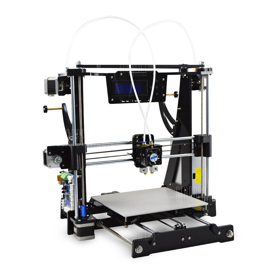
Page 4: Parts Picture
Parts Picture A3 A4 A5 A6 D2 D3 P1 P2 P2 Name Name Name Name Pulley gaskets Ball Bearing bracket Base Frame Left Hotend Frame Front Z Right Support Bottom Feeder piece Base Frame Right Hotend Frame Side Z Right Frame Ball Bearing bracket Base Frame Top Hotend Frame Top... -
Page 5: Screws And Nuts
Screws and nuts M3x30 Screw (x7) M3x6 Screw (x8) M2.5x15 Screw (x2) M8 nut (x12) 5x10 Shim (x4) M2.5 Nut (x2) M3 Nut (x60 ) M8 shim (x12) 5x7 E-Washer (x2) M3 Hand Nute (x4) M3x12 pole (x12) Φ4.5*22 Springs (x4) 5x6x7 Pole (x2) M3x16 Screw (x12) M3X20 Screw (x45) - Page 6 Pre-Assembled Assemble Y-axis belt pulley Assemble the ball bearing to Y-axis belt pulley holder, lock with screw and nut. Notice:smooth surface of shim towards ball bearing. Shim 6x20x1.2 *2 M5x35 Y-axis belt pulley holder *2 shim 5x10x0.8 *2 ball bearing 625zz M5 nut...
- Page 7 Pre-Assembled Assemble slider module(left) 1. Push bearings into slot, and then through the two bearings by sliding rod and test if it can move smoothly. 2. Install the M5 copper nut to the red part. 3. Insert the nylon pole to the red part, and mount a screw and spring and lock it. LM8UU *2 M3x30 M5 copper...
- Page 8 Pre-Assembled Assemble slider module(right) 1. Push bearings into slot, and then through the two bearings by sliding rod and test if it can move smoothly. 2. Mount the ball bearing to the part, use screw and nut to lock. 3. Install the M5 copper nut to the red part M5 Nut shim 5x10x0.8*2 M5x20...
- Page 9 Install X-axis Motor 1. Install a stepper motor (23mm shaft lenght) to the left silder, lock with 3 pcs M3x6 screws. 2. Mount one pulley to the stepper motor, lock the jbckscrew on the pulley. M3*6 x3 Note: Please pay attention to the installation direction of the pulley and the position on the motor shaft.
- Page 10 • Assemble Extruder Engine(EM4) clamp mechanism M3x6 motor holder shim M4 U-bearing jbckscrew M3x3 *2 Adapter M4x10 Video Tutorial...
- Page 11 Assemble LCD display module (LCD2004 Module) Install LCD2004 PCBA to acrylic piece,lock with 4 pcs M3x20 screws and M3 nuts. M3 nut *4 LCD2004 PCBA 5x7x6 pole *2 M3x20...
- Page 12 Assemble LCD display module (LCD12864 Module) Install LCD12864 PCBA to acrylic piece,lock with 4 pcs M3x20 screws and M3 nuts. 5x7x6 pole *4 M3 Nut *4 M3x20 LCD Mount LCD12864 PCBA Acrylic...
- Page 13 Assemble heatbed bracket 1. Mount 8 pcs poles on heatbed bracket, lock with 8 pcs M3x10 screws. 2. Put 4 pcs linear bearing (LM8UU) to the groove of the bracket. 3. Put the cover acrylics on the linear bearing and lock with 8 pcs M3x10 screws. cover acrylic *2 M3x12 pole *8 LM8UU *4...
- Page 14 Assemble Heat Bed Lock screws with nuts. MK3 heat bed M3 nut *4 M3x30 *4...
- Page 15 Assemble base frame front 1. Assemble Y-axis belt pulley on base frame front,lock with 2 pcs M3x20 screws and nuts. 2. Assemble lead rod restriction on base frame front, lock with 2 pcs M3x20 screws and nuts. M3x20 base frame lead rod front M3x20 *2...
- Page 16 Assemble base frame back Mount Y-axis motor and Y-axis ENDSTOP on Base Frame Back, lock with screws and nuts. Note: Please pay attention to the installation direction of the pulley lead rod base restriction frame M3x20 *5 back Y-axis motor motor holder Y-axis...
- Page 17 Assemble Z-axis motor(left) Mount Z-axis motor holder on Z-axis motor, lock with screws & nuts. Ball Bearing Ball Bearing Coupling bracket 625zz M3x30 *2 Bottom This hole towards right M3x10 *4 Lock it Wire connector M3 nut *2 This hole towards left Stepper motor...
- Page 18 Assemble Dual Extuder Hotend module 1.Fix the LM8UU linear bearing between the hotend frame back Bearing Cover. 2.Assemble the B1/B2/B3 with M3x16 screws and M3 nuts. 3. Install the Cooler fan to the hotend acrylic, take care the fan direction (lable toward hotend) and the wire direction.
- Page 19 Assemble Dual Extuder Hotend module lable toward hotend M3*10 *6 pole M3x12 *3 M3 nut *2 M3x16 *5 Frame Top LM8UU Frame Front M3 nut *5 M3x16 *2 4010 M2.5 nut *2 M3 nut *2 M3x10 *2 M2.5x15 *2 M3x16 *2 HE2 V3 Dual Extruder...
- Page 20 Assemble Z-axis timing pulley and bearing(Left and right) 2~3mm timing pulley Lock it after assemble Ball Bearing Jack shim M5 lead screw screw *2 Ball Bearing bracket Top M5 Elastic washer M5 nut *2 Right Left...
- Page 21 Install base frame bottom mount base frame bottom between base frame left base frame right, lock with M3x20 screws and M3 nuts. base frame left M3 nut *4 base frame right Note: left side has two hole M3x20 *4 base frame bottom...
- Page 22 Install Z-axis motor to base frame Mount Z-axis motor(left) and Z-axis support(right) on base frame bottom, lock with M3x20 screws and M3 nuts. base frame bottom Z-axis motor(left) M3 nut *4 M3x20 *4...
- Page 23 Install base frame top Mount base frame top base frame left base frame right, lock with M3x20 screws and M3 nuts. base frame top Note this hole on the right M3x20 *4 base frame left M3 nut *4 base frame right...
- Page 24 Install base frame back Mount base frame back between base frame left base frame right, lock with 4 pcs M3x20 screws and M3 nuts. M3x20 *4 M3 nut *4...
- Page 25 Install Y-axis lead screw Through the base frame back base frame bottom by 2 pcs M8x400mm lead screws, lock with 12 pcs M8 nuts and shims, adjust the position of nuts and properly. Lead screw M8x400 *2 M8 nut *8 M8 Shim *8...
- Page 26 Install base frame front 1. Mount one shim and one nut close base frame bottom. 2. Mount one nut and one shim close to base frame front. 3. Lock with one shim and one nut. Lead screw M8x400 *2 M8 nut *4 M8 Shim *4...
- Page 27 Install print plate 1. Let 2 pcs M8x380mm lead rods through base frame front and the linear bearing of heatbed bracket. 2. Fixed all of the sliding rod restriction to hold on the lead rods. 3. Tighten all of M8 nuts and shims. lead rod Heatbed Tighten M8 nuts of Y-axis lead screw...
- Page 28 Install Y-axis timing belt 90cm Timing belt Use one or two cable tie to lock the Belt. Note: Tighten the belt before locked.
- Page 29 Install Hot Bed Install the MK3 heatbed to the Heatbed bracket, put the springs between the heatbed and bracket, and lock with hand nuts. MK3 heatbed spring *4 Hand nut...
- Page 30 Install slider module left & rods Through junction plate slider module left by M8 lead rod,one end entering the hole on Z-axis motor(left). Insert lead rod First lead screw lead screw M5x347mm M5x365mm lead rod M8x345mm lead rod M8x345mm Slider module Slider right...
- Page 31 Install slider module right & rods Through juction plate and slider module left by screw rod,the bottom end on coupling,lock the jackscrew. M3x20 *4 M3 nut *4 jbckscrew *2 Lock it after assembled...
- Page 32 Assemble X-axis sliding rod & extruder 1.through slider module right, hotend and slider module left by two M8x380mm lead rods. 2.one of lead rod entering the hole on slide module left,the other leveled with slider module right’s hole edge. Lead rod M8x380mm *2 Hotend :Please insert the lead...
- Page 33 Assemble X-axis timing belt 1.Fixed one end of the timing belt on the hotend Acrylic Frame by cable tie. Through the belt pulley (X motor) and ball bearing (on the right slider module). 2. Tighten the belt and then fixed another end on the hotend by cable tie. 3.Cut extra belt.
- Page 34 Assemble Extruder Extruder 2 Engine M3x10 *2 M3x10 *2 Extruder Engine...
- Page 35 Install filament feeder M3x10 *2 Acrylic piece M3x45 pole Feeder pipe filament feeder M3 nut *2 M3x20 *2...
- Page 36 Install LCD display module(LCD2004) Install LCD display module on the top of base frame top,lock with M3x20 screws and M3 nuts. M3 nut *2 M3x20 *2 LCD2004 module...
- Page 37 Install Z-axis follow-up pulley M5x35 M5 shim *2 M5 nut Ball bearing Acrylic gaskets...
- Page 38 Install LCD display module(LCD12864) Install LCD display module on the base frame top,lock with M3x20 screws and M3 nuts. LCD12864 module M3 nut *2 M3x20 *2...
- Page 39 Install Z-axis ENDSTOP base frame left Mount Z-axis ENDSTOP on base frame left, lock with M3x20 screws and M3 nuts. P802C/P802CG P802CR2 M3x20 *2 Z-axis ENDSTOP M3 nut *2...
- Page 40 Install control board M3x10 X4 Install control board on base frame left,lock with screws and pole. control board M3x6 *4 pole M3x12 *4 M3x10 *4...
- Page 41 Assemble Z-axis timing belt Assemble the z-axis timing belt and adjust the position of follow-up pulley, let the belt keep proper tightness, then lock the follow-up pulley on the Base frame top close timing belt 710mm Move the follow-up pulley...
-
Page 42: Install Power Supply
Install power supply Install power supply to base frame right,lock with M3x10 screws. power supply M3x10 *3 Notice: Please set the 220V/110V switch(on the beside of power supply) before you assemble.More details please refer to wiring guide. - Page 43 Install filament run-out sensor Extruder Filament Filament Filament Run-out Sensor M3x20 *2 M3 nut *2...
- Page 44 Install PTFE tube Push the plastic ring on the Tube Fitting and then insert PTFE tube into fitting, to connect the extruder and hotend by PTFE tube. Filament PTFE Tube Fitting PTFE tube Insert Push PTFE Tube Fitting...
-
Page 45: Wiring Guide
Wiring Guide Attention. P802CR2 Wiring Diagram P802CUR2 Wiring Diagram Power Supply Wiring. APPEX I: How to change the direction of stepper motor APPEX II: How to adjust the current of motor Video Toturial Link: https://youtu.be/l09bXgQxo68... - Page 46 !Attention! The picture in this file may not match the actual machine, just for reference only. Take care when installation, to avoid electrical shock hazards! Once the connection is completed, please confirm again. WRONG WIRING MAY DAMAGED THE ELECTRONIC DEVICE! Operating current of some parts of are larger, please make sure the contact is good .
- Page 47 P802CR2 Wiring Diagram...
- Page 48 P802CUR2 Wiring Diagram...
-
Page 49: Power Supply Wiring
Power Supply Wiring The voltage of power supply is different depending on the country. Before wiring, please make sure this setting is right. AC power L, N, G must be correctly distinguished, or may endanger personal safety ! Attention Note: copper exposure is dangerous in AC V- is labeled as COM on line... - Page 50 APPEX I: How to change the direction of Stepper motor How to change the exchange the sequence of direction of the motor line, the motor step motor direction will be reversed 4Pin connector 4Pin connector plug to control plug to control board and 6Pin board and 6Pin connector plug...
- Page 51 APPEX II: How to adjust the current of motor 1.Rotate the potentiometer using a screwdriver, clockwise rotating the potentiometer will incerease the VREF, otherwise the VREF will be decreased. 2.Use a voltage meter to measure the value of Vref 3. Imotor = Vref*1.25 (A) e.g.
- Page 52 Level the heatbed 1. Refer to the below video to debug the Z axis (adjust the level of X printing platform). Video Tutorial link: https://youtu.be/U16MmsIaiEc 2. Refer to the below video to level the heat bed. Video Tutorial Link: https://youtu.be/QWsYR8NIGpc P802C Z axis Debug P802 Bed Level...
- Page 53 Adjust the height of the nozzle You need to ensure the nozzle is in the same height ( error is less than 0.2mm) before starting to print, please refer to the below steps to adjust the height if need. 1. Please refer to the previous steps to level the heat bed. 2.
- Page 54 Congratulations!
Need help?
Do you have a question about the P802CR2 and is the answer not in the manual?
Questions and answers