Table of Contents
Advertisement
Quick Links
EasyCollect 6000
< v > T - T y p 1 < / v >
< v > T - T y p 2 < / v > < / v >
< v > T - T y p 3 < / v > < / v >
< v > T - T y p 4 < / v > < / v >
< v > T - T y p 5 < / v > < / v >
(< v > T - a b M a s c h . - N r . < / v >
from serial
no.< / v >
Order
< v > T - B e s t e l l - N r . < / v >
no.< / v >
: 150 000 055 02 US
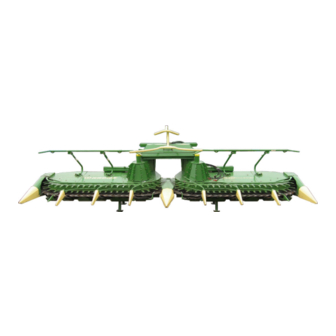
< v > B - T i t e l b i l d < / v >
Maize header
FP< / v >
: 782 200)
< v > T - T y p 6 < / v > < / v >
< v > T - T y p 7 < / v > < / v >
< v > T - T y p 8 < / v > < / v >
< v > T - T y p 9 < / v > < / v >
< v > T - T y p 1 0 < / v > < / v >
< / v >
Entwurf
Advertisement
Table of Contents

Related Manuals for Krone EasyCollect 6000 FP


Summary of Contents for Krone EasyCollect 6000 FP
- Page 1 Maize header < v > T - T y p 1 < / v > EasyCollect 6000 FP< / v > < v > T - T y p 6 < / v > < / v > < v > T - T y p 2 < / v > < / v > <...
- Page 2 Dear customer, customer, Dear You have now received the operating instructions for the KRONE product which you have purchased. These operating instructions contain important information for the proper use and safe operation of the machine. If these operating instructions should become wholly or partially unusable, you can obtain replacement operating instructions for your machine by stating the number given overleaf.
-
Page 3: Table Of Contents
Foreword Pos : 4 /BA/Inhalts verz eichnis Spr ac henneutr al @ 10\mod_1221574899104_0.doc @ 135495 Foreword ..............................7 Introduction ............................. 8 Purpose of Use ..........................8 Validity ............................... 8 2.2.1 Contact ............................8 Identification Plate ..........................9 Information Required for Questions and Orders................9 Intended Use ........................... - Page 4 Foreword 4.7.2 Type 493, type 494 ........................33 4.7.3 Connecting the hydraulic lines ..................... 35 Detaching the machine ........................37 4.8.1 Type 491, type 492 ........................39 4.8.2 Type 493, type 494 ........................40 Start-up – John Deere .......................... 41 Stop points ............................
- Page 5 Foreword Settings ..............................76 Adjusting skids ..........................77 Adjusting the plant dividers ......................77 Adjusting the angle of inclination of the maize header (CLAAS) ............. 78 Adjusting the angle of inclination of the maize header (John Deere) ..........79 Adjusting the angle of inclination of the maize header (New Holland) ..........80 9.5.1 Type FX (40,50,60 / 38,48,58) .....................
- Page 6 Foreword 10.14 Removing and installing insertion finger on the collector ............108 10.15 Blade Changing ......................... 109 10.15.1 Changing bow and step blades ..................... 109 10.15.2 Changing the cutting blades ....................111 10.15.3 Changing the scraper blade ....................112 10.15.4 Changing the dresser segments ....................
-
Page 7: Foreword
Pos : 6.2 /BA/Vor wort/Vorsätz e/Verehrter Kunde M aisgebiss @ 15\mod_1232634092971_78.doc @ 175232 Dear Customer! By purchasing the maize header, you have acquired a quality product made by KRONE. We are grateful for the confidence you have invested in us in buying this machine. -
Page 8: Introduction
Pos : 8.3 /BA/Ei nleitung/Vorsätze/Ver wendungsz wec k Eas yColl ect 6000 F P @ 15\mod_1233144092929_78.doc @ 179520 The Krone EASYCOLLECT 6000 FP maize header is a harvesting attachment with adapter frame for attachment to forage harvesters and is used for harvesting maize and other forage crop with stalks independently of the rows. -
Page 9: Identification Plate
Authentic KRONE spare parts and accessories authorised by the manufacturer help to ensure safety. The use of spare parts, accessories or additional equipment not manufactured, tested or approved by KRONE will exclude any liability for consequential damage. Pos : 8.11 /BA/-----Seitenumbruch------ @ 0\mod_1196175311226_0.doc @ 4165... -
Page 10: Intended Use
2.3.1 Ballast / forage harvester To ensure safe and reliable operation of the carrier vehicle with the Krone maize header attached, especially in road traffic, the ballast of the machine must be distributed evenly. Follow the specifications of the certificate of roadworthiness. -
Page 11: Machine Overview
Introduction Pos : 8.17 /Übersc hriften/Übersc hriften 2/K-O/Mas chi nenübersicht @ 0\mod_1195565731130_78.doc @ 555 Machine overview Pos : 8.18 /WHB/Allgemeines/Eas yColl ect 6000 FP/Eas yC ollect FP Voransic ht @ 16\mod_1235645739337_78.doc @ 199944 EasyCollect front view WHBEC0080 Fig. 2: EasyCollect front view Side part Rotating tower Collector including blades, right... - Page 12 Introduction Pos : 10 /BA/Di es e Seite is t bewusst freig elass en worden. @ 1\mod_1201783680373_78.doc @ 54443 This page has been left blank deliberately!! Pos : 11 /BA/-----Sei tenumbruch------ @ 0\mod_1196175311226_0.doc @ 4165...
-
Page 13: Safety
Safety Pos : 12.1 /Übersc hriften/Übersc hriften 1/P-T/Sicherheit @ 0\mod_1195566748646_78.doc @ 635 Safety Pos : 12.2 /BA/Sicher heit/Kennz eic hnung von Hi nweis en in der Betriebsanlei tung Ei nführ ungstext @ 0\mod_1195637804826_78.doc @ 1098 3.1.1 Identifying Symbols in the Operating Instructions The safety instructions contained in this manual which could result in personal injury if not followed are identified by the general danger sign: Pos : 12.3 /BA/Sicher heit/Kennz eic hnung der Gefahr enhi nweis e @ 0\mod_1195567454333_78.doc @ 693... -
Page 14: Personnel Qualification And Training
Safety Pos : 12.6.1 /BA/Sicherheit/Personalqualifi kati on und-Sc hul ung @ 0\mod_1195639383185_78.doc @ 1136 3.2.1 Personnel Qualification and Training The machine may be used, maintained and repaired only by persons who are familiar with it and have been instructed about the dangers connected with it. The operator must define areas of responsibility and monitoring of personnel. -
Page 15: Safety Instructions And Accident Prevention Regulations
Safety Pos : 12.6.5 /BA/Sicherheit/Sic her hei ts- und U nfall ver hütungs-Vorschriften M aisgebiss @ 15\mod_1232692324226_78.doc @ 175538 Safety Instructions and Accident Prevention Regulations Please follow all generally applicable safety and accident prevention regulations in addition to the safety instructions contained in these operating instructions! The attached warning and safety signs provide important information for safe operation. -
Page 16: Attached Devices
Pos : 12.6.7 /BA/Sicherheit/Angebaute Ger äte/Ger äte angebaut Maisg ebis s Z usatz Eas yColl ect 6000 F P @ 16\mod_1233145266116_78.doc @ 179682 On public highways, the maize header (EasyCollect 6000 FP) must always be in transport position. Attach guard cloths together with flashing lights and front guard to the maize header and connect the lighting. -
Page 17: Pto Operation
Safety Pos : 12.6.9 /BA/Sicherheit/Zapfwellenbetri eb Vorsätz e/F eldhäc ksler @ 13\mod_1225450981661_78.doc @ 156341 PTO Operation Use only PTO shafts specified by the manufacturer! The guard tube and guard cone of the PTO shaft and the PTO guard must be attached and in good working condition (on the implement side, too)! Make sure that the required tube covers are in place for PTO shafts in transport and working position! -
Page 18: Hydraulic System
Safety Pos : 12.6.12 /BA/Sic herheit/H ydrauli kanl age F eldhäc ksl er @ 0\mod_1195646239935_78.doc @ 1289 Hydraulic system The hydraulic system is pressurised! When connecting hydraulic cylinders and motors, make sure the hydraulic hoses are connected as specified! When connecting the hydraulic hoses to the forage harvester hydraulics, take care that the hydraulic system is depressurised both on the tractor side and on the device side! When functions are connected hydraulically between the forage harvester and the front attachment, coupling sleeves and plugs should be identified so that faulty operation is... -
Page 19: Maintenance
Replacement parts must at least comply with the technical requirements set by the manufacturer of the implements! This is guaranteed by original KRONE spare parts! Pos : 12.6.15 /BA/Sic herheit/Wartung/Wartung Z usatz Schneidwekz eug e @ 12\mod_1224578273531_78.doc @ 151591 When replacing working tools with cutting edges, use suitable tools and gloves! Pos : 12.6.16 /BA/-----Seitenumbruc h------ @ 0\mod_1196175311226_0.doc @ 4165... -
Page 20: Unauthorised Conversion/Modification And Spare Parts Production
Safety Pos : 12.6.17 /BA/Sic herheit/Eigenmäc htiger U mbau und Ers atz teil hers tell ung @ 1\mod_1201937705539_78.doc @ 55745 Unauthorised Conversion/Modification and Spare Parts Production Conversions or modifications of the machine are permitted only with prior consultation with the manufacturer. -
Page 21: Introduction
Pos : 12.8 /BA/Sicher heit/Vorsätz e/Sic herheit Einführung Maisg ebiss @ 15\mod_1232693161554_78.doc @ 175584 3.10 Introduction The KRONE cutting system is equipped with all the necessary safety devices (protective devices). However, it is not possible to eliminate all potential hazards on this machine as this would impair its full functional capability. -
Page 22: Position Of The Adhesive Safety Stickers On The Machine
Safety Pos : 12.12 /Ü berschriften/Ü berschriften 2/K-O/Lage der Sic her hei tsaufkl eber an der M asc hine @ 0\mod_1195634967326_78.doc @ 1020 3.12 Position of the Adhesive Safety Stickers on the Machine Pos : 12.13 /BA/Sic herheit/Aufkleber/Vors ätz e/Eas yCollect 6000_7500_9000 @ 15\mod_1232693490663_78.doc @ 175607 EC200021_2 Fig. - Page 23 Safety Danger from rotating auger. While parts are moving, never reach into areas where there is Order No. 939 520 1 (2x) a risk of being crushed. Order No. 942 196-1 (2x) 939 520-1 942 196 -1 Do not stay in the swivel range Do not climb onto the machine of the outrigger arms! Keep if the PTO shaft is connected...
-
Page 24: Position Of The General Information Labels On The Machine
Safety Pos : 12.15 /Ü berschriften/Ü berschriften 2/K-O/Lage der allgemeinen Hinweisaufkl eber an der M asc hine @ 0\mod_1195635067920_78.doc @ 1039 3.13 Position of the General Information Labels on the Machine Pos : 12.16 /BA/Sic herheit/Vors ätze/Hi nweisaufkl eber Eas yColl ect 6000 F P @ 16\mod_1233145780726_78.doc @ 179748 EC200022 Fig. -
Page 25: Re-Ordering The Adhesive Safety And Information Labels
Safety Pos : 12.18 /BA/Sic herheit/N ac hbestellung/ Anbring ung Aufkleber @ 0\mod_1195637337107_78.doc @ 1079 3.13.1 Re-Ordering the Adhesive Safety and Information Labels Note Every adhesive safety and information label is assigned an order number and can be ordered directly from the manufacturer or from an authorized dealer (see Section "Contact"). -
Page 26: Start-Up -Claas
Pos : 14.3 /BA/Sicher heit/Gefahr enhinweis e/Vors ätz e/An- / Abbau M aisgebiss Z us atz Eas yC ollec t 6000 FP @ 16\mod_1233146487288_78.doc @ 179841 • On public highways, the EASYCOLLECT 6000 FP maize header must always be in the transport position. The transport height must also be set so that the max. -
Page 27: Stop Points
Start-up -CLAAS Pos : 14.5 /WHB/Übersc hriften 2/A-E/Ansc hlag punkte @ 7\mod_1216717518036_78.doc @ 106550 Stop points Pos : 14.6 /BA/Inbetriebnahme/Vorsätze/Ansc hlag punkte Gefahrhi nweis @ 12\mod_1224668106422_78.doc @ 152419 Warning! Stop and transportation equipment inadequately dimensioned. Effect: Danger to life, serious injuries or serious damage to the machine Use only adequately dimensioned stop and transportation equipment (crane, ropes)! Pos : 14.7 /BA/Inbetriebnahme/Vorsätze/X-Disc 6200/Adapterrahmen/Ans chl agpunkte Bil d Eas yC ollect 6000 F P @ 16\mod_1235649805853_78.doc @ 199996... -
Page 28: Attachment To The Claas Forage Harvester
CLAAS forage harvesters of the Jaguar series 8xx and 9xx (820, 830, 840, 850, 860, 870, 880, 890 and 900). The Krone EASYCOLLECT 6000 FP maize header is used for harvesting maize and other forage crop with stalks independently of rows. -
Page 29: Preparations On The Forage Harvester (Type 493, Type 494)
Start-up -CLAAS Pos : 14.19 /BA/Inbetri ebnahme/Vors ätz e/M aisgebiss/C LAAS/Vor ber eitungen am F eldhäc ksl er (T yp 493;494) T 1 @ 16\mod_1233155430788_78.doc @ 180076 Preparations on the forage harvester (type 493, type 494) Fig. 9: • Unscrew the screws (2) and remove guard plate (1). •... -
Page 30: Preparations On The Easycollect
Start-up -CLAAS Pos : 14.22 /BA/Inbetri ebnahme/Vors ätz e/M aisgebiss/Vor bereitung Bel euchtung Fremdfabrikat @ 18\mod_1236932905956_78.doc @ 207456 Preparations for lighting (Germany only) The headlights mounted as standard equipment (for dipped beam and full beam) are covered in road position by the side parts of the maize header. Therefore the headlights (for dipped beam and full beam) must be mounted on the cab roof with the forage harvester manufacturer's kit. -
Page 31: Coupling
Start-up -CLAAS Pos : 14.27 /Ü berschriften/Ü berschriften 2/A-E/Ankuppel n @ 16\mod_1233156207726_78.doc @ 180144 Coupling Pos : 14.28 /BA/Inbetri ebnahme/Vors ätz e/M aisgebiss/C LAAS/T ype 491,492 @ 16\mod_1235567555854_78.doc @ 198943 4.7.1 Type 491, type 492 Pos : 14.29 /BA/Inbetri ebnahme/Vors ätz e/M aisgebiss/C LAAS/Ankuppeln CLAAS T ype 491,492 T 1 @ 16\mod_1233156349288_78.doc @ 180169 ECF00003_2 Fig. - Page 32 Start-up -CLAAS Pos : 14.31 /BA/Inbetri ebnahme/Vors ätz e/M aisgebiss/C LAAS/Ankuppeln CLAAS T 2 T ype 491/492 @ 16\mod_1233156759695_78.doc @ 180192 Fig. 13: • Fold down the protective cover (9). • Push the universal joint (10) onto the drive journal of the forage harvester gearbox until the lock engages.
-
Page 33: Type 493, Type 494
Start-up -CLAAS Pos : 14.33 /BA/Inbetri ebnahme/Vors ätz e/M aisgebiss/C LAAS/T ype 493,494 @ 16\mod_1235567636385_78.doc @ 199057 4.7.2 Type 493, type 494 Pos : 14.34 /BA/Inbetri ebnahme/Vors ätz e/M aisgebiss/C LAAS/Ankuppeln CLAAS T ype 493,494 T1 @ 16\mod_1235568125104_78.doc @ 199139 ECF00022 Fig. - Page 34 Start-up -CLAAS Fig. 16: • Assemble the guard (9) over the PTO shaft (10) onto the gearbox (11) and mount the support (12). Pos : 14.37 /BA/-----Seitenumbruc h------ @ 0\mod_1196175311226_0.doc @ 4165...
-
Page 35: Connecting The Hydraulic Lines
Start-up -CLAAS Pos : 14.38 /Ü berschriften/Ü berschriften 3/A-E/Anschl uss der H ydrauli kleitungen @ 0\mod_1199777037794_78.doc @ 34244 4.7.3 Connecting the hydraulic lines Pos : 14.39 /BA/Sic herheit/H ydrauli k/Anschl uss der H ydrauli kleitungen Vors atzger äte/F eldhäc ksler @ 15\mod_1232703918429_78.doc @ 175905 Warning! Connection of the hydraulic line Effect: Serious injury due to hydraulic oil penetrating the skin. - Page 36 Start-up -CLAAS Pos : 14.43 /BA/Inbetri ebnahme/Vors ätz e/M aisgebiss/C LAAS/H ydrauli k/Bel euc htung ansc hließ en Bil d C LAAS @ 16\mod_1233218818751_78.doc @ 180238 ECF00006 Fig. 17: Pos : 14.44 /BA/Inbetri ebnahme/Vors ätz e/M aisgebiss/H ydr auli k/Beleuchtung ans chli eßen T ext Claas/JohnD eere/N ewH olland @ 16\mod_1233242722735_78.doc @ 181395 A double-action hydraulic connection is required to operate the maize header.
-
Page 37: Detaching The Machine
Start-up -CLAAS Pos : 14.47 /Ü berschriften/Ü berschriften 2/A-E/Abbau der M asc hine @ 3\mod_1204792387824_78.doc @ 73245 Detaching the machine Pos : 14.48 /BA/Sic herheit/Vors ätze/M asc hine abstellen M aisgebiss @ 15\mod_1232951059911_78.doc @ 176604 Danger! Unexpected movements of the machine Effect: Danger to life, serious injuries •... - Page 38 Start-up -CLAAS Pos : 14.52 /BA/Bedienung /Vorsätze/Maisgebiss /CLAAS/Abbau T2 Bil d Eas yC ollecct 6000 F P C LAAS @ 16\mod_1233220219157_78.doc @ 180283 ECF00009 Fig. 19: Pos : 14.53 /BA/Inbetri ebnahme/Vors ätz e/M aisgebiss/Ac htung U nfall- und Besc hädigungsgefahr! Hydrauli kleitung @ 15\mod_1232700232445_78.doc @ 175771 Caution! Danger of accident and damage! Place hydraulic hoses (1) and electrical connection line (2,3) on the maize...
-
Page 39: Type 491, Type 492
Start-up -CLAAS Pos : 14.57 /BA/Inbetri ebnahme/Vors ätz e/M aisgebiss/C LAAS/T ype 491,492 @ 16\mod_1235567555854_78.doc @ 198943 4.8.1 Type 491, type 492 Pos : 14.58 /BA/Bedienung /Vorsätze/Maisgebiss /CLAAS/Abbau T3 Bil d T yp 491,492 Eas yC ollecc t 6000 FP CLAAS @ 16\mod_1233220936860_78.doc @ 180352 ECF00010_2 Fig. -
Page 40: Type 493, Type 494
Start-up -CLAAS Pos : 14.62 /BA/Inbetri ebnahme/Vors ätz e/M aisgebiss/C LAAS/T ype 493,494 @ 16\mod_1235567636385_78.doc @ 199057 4.8.2 Type 493, type 494 Pos : 14.63 /BA/Bedienung /Vorsätze/Maisgebiss /CLAAS/Abbau T4 Bil d Eas yC ollect F P @ 16\mod_1233221331532_78.doc @ 180399 ECF00010_2 Fig. -
Page 41: Start-Up - John Deere
Pos : 16.3 /BA/Sicher heit/Gefahr enhinweis e/Vors ätz e/An- / Abbau M aisgebiss Z us atz Eas yC ollec t 6000 FP @ 16\mod_1233146487288_78.doc @ 179841 • On public highways, the EASYCOLLECT 6000 FP maize header must always be in the transport position. The transport height must also be set so that the max. -
Page 42: Stop Points
Start-up – John Deere Pos : 16.5 /WHB/Übersc hriften 2/A-E/Ansc hlag punkte @ 7\mod_1216717518036_78.doc @ 106550 Stop points Pos : 16.6 /BA/Inbetriebnahme/Vorsätze/Ansc hlag punkte Gefahrhi nweis @ 12\mod_1224668106422_78.doc @ 152419 Warning! Stop and transportation equipment inadequately dimensioned. Effect: Danger to life, serious injuries or serious damage to the machine Use only adequately dimensioned stop and transportation equipment (crane, ropes)! Pos : 16.7 /BA/Inbetriebnahme/Vorsätze/X-Disc 6200/Adapterrahmen/Ans chl agpunkte Bil d Eas yC ollect 6000 F P @ 16\mod_1235649805853_78.doc @ 199996... -
Page 43: Mounting On John Deere Forage Harvesters
7xxx (6610, 6710, 6810, 6910, 6650, 6750, 6850, 6950 and 7200, 7300, 7400, 7700, 7800, 7250, 7350, 7450, 7550, 7750 and 7850). The Krone EASYCOLLECT 6000 FP maize header is used for harvesting maize and other forage crop with stalks independently of rows. -
Page 44: Preparations On The Easycollect
Start-up – John Deere Pos : 16.19 /BA/Inbetri ebnahme/Vors ätz e/M aisgebiss/Vor bereitung Bel euchtung Fremdfabrikat @ 18\mod_1236932905956_78.doc @ 207456 Preparations for lighting (Germany only) The headlights mounted as standard equipment (for dipped beam and full beam) are covered in road position by the side parts of the maize header. -
Page 45: Coupling
Start-up – John Deere Pos : 16.24 /Ü berschriften/Ü berschriften 2/A-E/Ankuppel n @ 16\mod_1233156207726_78.doc @ 180144 Coupling Pos : 16.25 /BA/Inbetri ebnahme/Vors ätz e/M aisgebiss/J ohnD eere/Ankuppel n J ohn D eere T1 @ 16\mod_1233240297907_78.doc @ 181254 Fig. 25: • Before moving the forage harvester forward, open the protective cover (4). - Page 46 Start-up – John Deere ECF00124 Fig. 27: • Push the universal joint (2) onto the maize header gearbox until the lock engages. • Push the universal joint (1) onto the drive journal of the forage harvester gearbox until the lock engages. Note Check the alignment of the universal joint and correct the position of the gearbox journal in the outer gearbox (3) if necessary.
- Page 47 Start-up – John Deere Fig. 29: For John Deere forage harvester types of series 77xx and 78xx, it might be necessary to increase the height of the maize header on the right (as seen in direction of travel) when mounting the universal joint. To do this: •...
-
Page 48: Connecting The Hydraulic Lines
Start-up – John Deere Pos : 16.31 /Ü berschriften/Ü berschriften 3/A-E/Anschl uss der H ydrauli kleitungen @ 0\mod_1199777037794_78.doc @ 34244 5.6.1 Connecting the hydraulic lines Pos : 16.32 /BA/Sic herheit/H ydrauli k/Anschl uss der H ydrauli kleitungen Vors atzger äte/F eldhäc ksler @ 15\mod_1232703918429_78.doc @ 175905 Warning! Connection of the hydraulic line Effect: Serious injury due to hydraulic oil penetrating the skin. - Page 49 Start-up – John Deere Pos : 16.36 /BA/Inbetri ebnahme/Vors ätz e/M aisgebiss/J ohnD eere/H ydr auli k/Beleuc htung ans chli eßen Bild JohnDeere @ 16\mod_1233242864016_78.doc @ 181418 Fig. 30: Pos : 16.37 /BA/Inbetri ebnahme/Vors ätz e/M aisgebiss/H ydr auli k/Beleuchtung ans chli eßen T ext Claas/JohnD eere/N ewH olland @ 16\mod_1233242722735_78.doc @ 181395 A double-action hydraulic connection is required to operate the maize header.
-
Page 50: Detaching The Machine
Start-up – John Deere Pos : 16.40 /Ü berschriften/Ü berschriften 2/A-E/Abbau der M asc hine @ 3\mod_1204792387824_78.doc @ 73245 Detaching the machine Pos : 16.41 /BA/Sic herheit/Vors ätze/M asc hine abstellen M aisgebiss @ 15\mod_1232951059911_78.doc @ 176604 Danger! Unexpected movements of the machine Effect: Danger to life, serious injuries •... - Page 51 Start-up – John Deere Pos : 16.45 /BA/Inbetri ebnahme/Vors ätz e/M aisgebiss/J ohnD eere/H ydr auli k/Beleuc htung ans chli eßen Bild JohnDeere @ 16\mod_1233242864016_78.doc @ 181418 Fig. 32: Pos : 16.46 /BA/Inbetri ebnahme/Vors ätz e/M aisgebiss/Ac htung U nfall- und Besc hädigungsgefahr! Hydrauli kleitung @ 15\mod_1232700232445_78.doc @ 175771 Caution! Danger of accident and damage! Place hydraulic hoses (1) and electrical connection line (2,3) on the maize...
- Page 52 Start-up – John Deere ECF00127 Fig. 34: • Loosen the locking pins (1). To do this: • Remove the linch pin (3) and move screw (3) from pos. II to pos. I. • Lower the feed drive housing (4) until the holding bracket (5) is positioned under the cross-pipe (6) of the maize header support panel.
-
Page 53: Start-Up - New Holland
Moving the PTO shafts on the change-over gearbox changes the speed. Effect: Damage to the machine The speed setting for the EasyCollect 6000 FP is preset in the factory (to a transmission ratio of 1:1) and must not be changed by moving the PTO shafts on the change-over gearbox. -
Page 54: Stop Points
Start-up - New Holland Pos : 18.8 /WHB/Übersc hriften 2/A-E/Ansc hlag punkte @ 7\mod_1216717518036_78.doc @ 106550 Stop points Pos : 18.9 /BA/Inbetriebnahme/Vorsätze/Ansc hlag punkte Gefahrhi nweis @ 12\mod_1224668106422_78.doc @ 152419 Warning! Stop and transportation equipment inadequately dimensioned. Effect: Danger to life, serious injuries or serious damage to the machine Use only adequately dimensioned stop and transportation equipment (crane, ropes)! Pos : 18.10 /BA/Inbetri ebnahme/Vors ätz e/X-Disc 6200/Adapterr ahmen/Ansc hlag punkte Bild Eas yC ollec t 6000 FP @ 16\mod_1235649805853_78.doc @ 199996... -
Page 55: Mounting On New Holland Forage Harvesters
Pos : 18.19 /BA/Ei nlei tung/Vors ätz e/Ver wendungsz wec k Eas yC ollect 6000 FP NewH olland @ 16\mod_1233235696829_78.doc @ 181012 The Krone maize header EASYCOLLECT 6000 FP is a harvesting attachment with an adapter frame designed exclusively for attachment to New Holland forage harvester models of series FX (38,48,58), FX (40,50,60) and FR 90. -
Page 56: Preparations On The Easycollect
Start-up - New Holland Pos : 18.23 /BA/Inbetri ebnahme/Vors ätz e/M aisgebiss/Vor bereitung Bel euchtung Fremdfabrikat @ 18\mod_1236932905956_78.doc @ 207456 Preparations for lighting (Germany only) The headlights mounted as standard equipment (for dipped beam and full beam) are covered in road position by the side parts of the maize header. -
Page 57: Coupling
Start-up - New Holland Pos : 18.28 /Ü berschriften/Ü berschriften 2/A-E/Ankuppel n @ 16\mod_1233156207726_78.doc @ 180144 Coupling Pos : 18.29 /BA/Inbetri ebnahme/Vors ätz e/M aisgebiss/N ewH olland/T ype F X ( 40,50,60 / 38,48,58) @ 16\mod_1235633294681_78.doc @ 199424 Type FX (40,50,60 / 38,48,58) Pos : 18.30 /BA/Inbetri ebnahme/Vors ätz e/M aisgebiss/N ewH olland/Ankuppel n N ewH olland Bild T yp FX @ 16\mod_1235651560806_78.doc @ 200174 FX 38 FX 48... - Page 58 Start-up - New Holland Pos : 18.33 /BA/Inbetri ebnahme/Vors ätz e/M aisgebiss/N ewH olland/Ankuppel n N ewH olland T1 Zus atz FX 38,48,58 @ 16\mod_1235651798337_78.doc @ 200249 Types of series FX (38,48,58): • Using the locking lever (9), swivel the locks (5) (right and left side of the machine) over the lock holders (6).
- Page 59 Start-up - New Holland Pos : 18.38 /BA/Inbetri ebnahme/Vors ätz e/M aisgebiss/N ewH olland/T ype FR 90 @ 16\mod_1235641370134_78.doc @ 199720 Type FR 90 Pos : 18.39 /BA/Inbetri ebnahme/Vors ätz e/M aisgebiss/N ewH olland/Ankuppel n N ewH olland Bild T yp FR @ 16\mod_1235652230134_78.doc @ 200349 ECFH0018 Fig.
- Page 60 Start-up - New Holland Pos : 18.42 /BA/Inbetri ebnahme/Vors ätz e/M aisgebiss/N ewH olland/Ankuppel n N ewH olland T1 Zus atz T yp FR 90 @ 16\mod_1233294142831_78.doc @ 181684 Types of series FR 90 • Using the locking lever (9), swivel the locks (5) (right and left side of the machine) over the lock holders (6).
- Page 61 Start-up - New Holland Pos : 18.46 /BA/Inbetri ebnahme/Vors ätz e/M aisgebiss/N ewH olland/Ankuppel n N ewH olland T2 @ 16\mod_1233294559550_78.doc @ 181707 ECFH0004_1 Fig. 41: • Push the PTO shaft (1) onto the drive journal of the forage harvester gearbox until the lock engages.
-
Page 62: Connecting The Hydraulic Lines
Start-up - New Holland Pos : 18.49 /Ü berschriften/Ü berschriften 3/A-E/Anschl uss der H ydrauli kleitungen @ 0\mod_1199777037794_78.doc @ 34244 6.7.1 Connecting the hydraulic lines Pos : 18.50 /BA/Sic herheit/H ydrauli k/Anschl uss der H ydrauli kleitungen Vors atzger äte/F eldhäc ksler @ 15\mod_1232703918429_78.doc @ 175905 Warning! Connection of the hydraulic line Effect: Serious injury due to hydraulic oil penetrating the skin. - Page 63 Start-up - New Holland Pos : 18.54 /BA/Inbetri ebnahme/Vors ätz e/M aisgebiss/N ewH olland/T ype F X ( 40,50,60 / 38,48,58) @ 16\mod_1235633294681_78.doc @ 199424 Type FX (40,50,60 / 38,48,58) Pos : 18.55 /BA/Inbetri ebnahme/Vors ätz e/M aisgebiss/N ewH olland/H ydr auli k/Beleuc htung anschli eßen Bild NewH olland @ 16\mod_1233295940847_78.doc @ 181730 Fig.
- Page 64 Start-up - New Holland Pos : 18.59 /BA/Inbetri ebnahme/Vors ätz e/M aisgebiss/N ewH olland/T ype FR 90 @ 16\mod_1235641370134_78.doc @ 199720 Type FR 90 Pos : 18.60 /BA/Inbetri ebnahme/Vors ätz e/M aisgebiss/N ewH olland/H ydr auli k/Beleuc htung anschli eßen Bild NewH olland FR @ 17\mod_1235719979667_78.doc @ 200608 ECFH0019 Fig.
-
Page 65: Detaching The Machine
Start-up - New Holland Pos : 18.64 /Ü berschriften/Ü berschriften 2/A-E/Abbau der M asc hine @ 3\mod_1204792387824_78.doc @ 73245 Detaching the machine Pos : 18.65 /BA/Sic herheit/Vors ätze/M asc hine abstellen M aisgebiss @ 15\mod_1232951059911_78.doc @ 176604 Danger! Unexpected movements of the machine Effect: Danger to life, serious injuries •... - Page 66 Start-up - New Holland Pos : 18.69 /BA/Inbetri ebnahme/Vors ätz e/M aisgebiss/N ewH olland/H ydr auli k/Beleuc htung anschli eßen Bild NewH olland @ 16\mod_1233295940847_78.doc @ 181730 Fig. 46: Pos : 18.70 /BA/Inbetri ebnahme/Vors ätz e/M aisgebiss/Ac htung U nfall- und Besc hädigungsgefahr! Hydrauli kleitung @ 15\mod_1232700232445_78.doc @ 175771 Caution! Danger of accident and damage! Place hydraulic hoses (1) and electrical connection line (2,3) on the maize...
- Page 67 Start-up - New Holland ECFH0008_1 Fig. 48: • Loosen the lock (5) with a suitable tool (for example an open face wrench). • Swivel up the locks (5) (on the right and left side of the machine). • Lower the feed drive housing (1) with the lifting hydraulics until the holder (3) is positioned under the support pipe (4).
-
Page 68: Driving And Transport
Pos : 20.3 /BA/Sicher heit/Fahren und Transport/Mitfahr en/Zus atz Eas yC ollect 6000 F P @ 16\mod_1233151017820_78.doc @ 179975 • On public highways, the EASYCOLLECT 6000 FP maize header must always be in transport position. The transport height must also be set so that the max. - Page 69 Driving and Transport Pos : 20.6 /BA/F ahren und Tr ans port/Vors ätz e/Str aßenfahrt M aisgebis Bil d @ 16\mod_1233149052148_78.doc @ 179911 Fig. 49: Pos : 20.7 /BA/F ahren und Tr ans port/Vors ätz e/Vorbereitung Str aßenfahrt Eas yColl ect 6000 F P @ 17\mod_1235718817495_78.doc @ 200558 During transportation / road travel the maize header must be raised.
-
Page 70: Operation
Operation Pos : 22.1 /Übersc hriften/Übersc hriften 1/A-E/Bedienung @ 0\mod_1199789505403_78.doc @ 34825 Operation Pos : 22.2 /Übersc hriften/Übersc hriften 2/U-Z/Von Trans port in Ar beitsstellung @ 2\mod_1202466185276_78.doc @ 59662 From transport into working position Pos : 22.3 /BA/Sicher heit/Gefahr enhinweis e/Vors ätz e/Absenken des Vorsatzes @ 15\mod_1232708075710_78.doc @ 176250 Danger! Lowering the machine into working position Effect: Danger to life, injuries or damage to the machine. -
Page 71: Using The Machine For Work
Moving the PTO shafts on the change-over gearbox changes the speed. Effect: Damage to the machine The speed setting for the EasyCollect 6000 FP is preset in the factory (to a transmission ratio of 1:1) and must not be changed by moving the PTO shafts on the change-over gearbox. -
Page 72: Using The Maize Header
Operation Pos : 22.13 /BA/Bedienung /Vorsätze/Maisgebiss /Maisgebiss ei nsetz en @ 15\mod_1232949053833_78.doc @ 176425 8.2.1 Using the maize header Note Clean cut • The collector speed must not be higher than the feed rate of the crop into the harvester. The speed must be set as high as is required to ensure a clean cut crop. -
Page 73: Switching From Working Position To Transport Position
Operation Pos : 22.18 /Ü berschriften/Ü berschriften 2/U-Z/Von Arbeits stellung i n Tr ansportstellung @ 2\mod_1202466246542_78.doc @ 59681 Switching from working position to transport position Pos : 22.19 /BA/Sic herheit/Gefahrenhinweise/Vorsätz e/U mstellung in Trans portstell ung @ 16\mod_1233224761985_78.doc @ 180509 Danger! Folding in the front attachment to transport position Effect: Danger to life, injuries or damage to the machine. -
Page 74: Parking Supports In Transport Position On The Right/Left
Operation Pos : 22.25 /Ü berschriften/Ü berschriften 3/A-E/Abstellstütz en rec hts /links in Tr ansportstellung @ 15\mod_1232964423395_78.doc @ 177066 8.3.1.1 Parking supports in transport position on the right/left Pos : 22.26 /BA/Bedienung /Vorsätze/Maisgebiss /Abstellstütz e i n Trans por tstellung @ 15\mod_1232965687880_78.doc @ 177226 Fig. -
Page 75: Connecting Indicators And Position Lights On The Right/Left
Operation Pos : 22.31 /Ü berschriften/Ü berschriften 3/A-E/Blink- und Positi onsleuchten r ec hts/li nks ansc hließ en @ 15\mod_1232964594364_78.doc @ 177111 8.3.3 Connecting indicators and position lights on the right/left Pos : 22.32 /BA/Bedienung /Vorsätze/Maisgebiss /Blink- und Positi onsleuc hten rec hts / links anschli eßen @ 15\mod_1232965918520_78.doc @ 177270 Fig. -
Page 76: Settings
Settings Pos : 24.1 /Übersc hriften/Übersc hriften 1/A-E/Ei nstellungen @ 0\mod_1199868783862_78.doc @ 36141 Settings Pos : 24.2 /BA/Sicher heit/Gefahr enhinweis e/Vors ätz e/Gefahr Wartung allgemei n Maisg ebis s/F eldhäc ksler @ 15\mod_1232963099583_78.doc @ 176970 Danger! When performing repair, maintenance or cleaning work or when making technical modifications to the machine, drive elements may start moving (caution: cutting discs continue to run). -
Page 77: Adjusting Skids
Settings Pos : 24.4 /Übersc hriften/Übersc hriften 2/F-J/Gl eitkufe eins tell en @ 15\mod_1232966442176_78.doc @ 177311 Adjusting skids Pos : 24.5 /BA/Eins tell ung en/Vorsätze/Maisg ebiss /Hinweis Gleitkufen @ 15\mod_1232966709848_78.doc @ 177361 Note The position of the skids (1) determines the min. stubble length. Adjust all skids equally. -
Page 78: Adjusting The Angle Of Inclination Of The Maize Header (Claas)
Settings Adjusting the angle of inclination of the maize header (CLAAS) Fig. 58: You can adjust the angle of inclination with the receiving pockets (1). Hole row (I) standard setting Hole row (II) medium angle of inclination Hole row (III) large angle of inclination Pre-condition: The forage harvester must be disconnected from the maize header. -
Page 79: Adjusting The Angle Of Inclination Of The Maize Header (John Deere)
Settings Pos : 25.3 /BA/Eins tell ung en/Vorsätze/J ohnD eer e/N eigungs wi nkel des M aisgebiss e einstellen JohnD eere @ 16\mod_1233244518157_78.doc @ 181535 Adjusting the angle of inclination of the maize header (John Deere) II I ECF00128 Fig. 59: You can adjust the angle of inclination with the support panel (1). -
Page 80: Adjusting The Angle Of Inclination Of The Maize Header (New Holland)
Settings Pos : 25.5 /BA/Eins tell ung en/Vorsätze/NewH olland/N eigungs wi nkel des M aisgebiss e eins tell en NewH olland @ 16\mod_1233296723738_78.doc @ 181847 Adjusting the angle of inclination of the maize header (New Holland) 9.5.1 Type FX (40,50,60 / 38,48,58) ECFH0013 Fig. -
Page 81: Block Pendulum Frame
Settings Pos : 25.7 /BA/Eins tell ung en/Vorsätze/CLAAS/Pendelrahmen s perr en CLAAS/J ohnD eer e/N ew H olland @ 16\mod_1233226310251_78.doc @ 180603 Block pendulum frame Fig. 61: You can block the swinging of the EasyCollect during operation with the locking lever (1). To do this: •... -
Page 82: Adjustment Of The Compensation Springs
Settings Pos : 25.10 /BA/Ei nstellungen/Vors ätz e/C LAAS/Eins tell ung der Entlastungsfeder n C LAAS/JohnDeere/New Holl and @ 16\mod_1233226715095_78.doc @ 180647 Adjustment of the compensation springs Fig. 63: The compensation springs (1) on the right and left side of the machine pull the EasyCollect in central position when the front attachment is lifted. -
Page 83: Change-Over Gearbox
Moving the PTO shafts on the change-over gearbox changes the speed. Effect: Damage to the machine The speed setting for the EasyCollect 6000 FP is preset in the factory (to a transmission ratio of 1:1) and must not be changed by moving the PTO shafts on the change-over gearbox. - Page 84 Settings Pos : 25.17 /BA/Ei nstellungen/Vors ätz e/U mstec kgetri ebe Dr ehz ahl T abelle @ 17\mod_1235728939495_78.doc @ 200784 left side right side Pos. II Pos. I Pos. II Pos. I Pos. IV Pos. III Pos. III Pos. IV Pos.I Pos.III 100%...
-
Page 85: Moving The Pto Shafts On The Change-Over Gearbox
Settings Pos : 25.19 /BA/Ei nstellungen/Vors ätz e/U mstec ken der Gelenkwellen am U mstec kg etriebe @ 16\mod_1233297291331_78.doc @ 181892 9.9.1 Moving the PTO shafts on the change-over gearbox ECF00021 Fig. 66: To do this: • Remove the protective cover (7). •... - Page 86 Settings This page has been left blank deliberately!! Pos : 26 /BA/-----Sei tenumbruch------ @ 0\mod_1196175311226_0.doc @ 4165...
-
Page 87: Maintenance
Effect: Danger to life, serious injuries or loss of warranty claims as well as exclusion of liability • Use only authentic KRONE spare parts and accessories authorised by the manufacturer. The use of spare parts, accessories or additional equipment not manufactured, tested or approved by KRONE will exclude any liability for consequential damage. -
Page 88: Torques
Maintenance Pos : 27.9 /BA/Wartung/Drehmomente @ 14\mod_1227524875870_78.doc @ 169435 10.3 Torques A = Thread size Tightening torque M is stated in Nm (unless (The stability class can be seen on the head of the otherwise indicated). screw.) 5.6 6.8 10.9 12.9 MA (Nm) Ø... -
Page 89: Torques (Countersunk Screws)
Maintenance Pos : 27.13 /BA/Wartung/Drehmomente über Innensechs kant @ 14\mod_1227525062214_78.doc @ 169458 10.4 Torques (Countersunk Screws) A = Thread size Tightening torque M is stated in Nm (unless (The stability class can be seen on the head of the otherwise indicated). screw.) 10.9 12.9 MA (Nm) -
Page 90: Tightening Torques On Aluminium Gearboxes
Maintenance Pos : 27.17 /BA/Wartung/Vorsätz e/Anz ugs momente an den Al uminium- Getrieben @ 15\mod_1233128522179_78.doc @ 178112 10.4.1 Tightening torques on aluminium gearboxes Fig. 67: Pos : 27.18 /BA/-----Seitenumbruc h------ @ 0\mod_1196175311226_0.doc @ 4165... -
Page 91: Filling Quantities And Lubrication Designations For Gearboxes
Maintenance Pos : 27.19 /Ü berschriften/Ü berschriften 2/F-J/Füll mengen und Sc hmier mittel bez eic hnungen der Getriebe @ 0\mod_1196951094046_78.doc @ 15335 10.5 Filling Quantities and Lubrication Designations for Gearboxes Pos : 27.20 /BA/Wartung/Tabellen/Vors ätz e/T abelle F üllmeng en Eas yC ollec t 6000 FP @ 16\mod_1233227307032_78.doc @ 180691 Filling Bio-degradable Filtered oils... -
Page 92: Checking The Oil Level And Changing The Oil On The Spur Wheel Gearbox
Maintenance Pos : 27.25 /WH B/Ü berschriften 3/K-O/Ölstands kontroll e und Ölwec hs el am Stirnradgetri ebe @ 18\mod_1236939742206_78.doc @ 207610 10.5.2 Checking the oil level and changing the oil on the spur wheel gearbox Pos : 27.26 /Ü berschriften/Ü berschriften 4/F-J/John D eer e / New H olland @ 16\mod_1233298579863_0.doc @ 181960 10.5.2.1 John Deere / New Holland Pos : 27.27.1 /WH B/Wartung/Eas yCollect 6000/7500/9000/Öls tands kontr olle in Arbeitss tell ung durchführen @ 9\mod_1219831368796_78.doc @ 123361... -
Page 93: Checking The Oil Level And Changing The Oil On The Main Angular Gearbox
Maintenance Pos : 27.29 /WH B/Ü berschriften 3/K-O/Ölstands kontroll e und Ölwec hs el am Hauptwinkelgetriebe @ 9\mod_1219831262890_78.doc @ 123340 10.5.3 Checking the Oil Level and Changing the Oil on the Main Angular Gearbox Pos : 27.30 /Ü berschriften/Ü berschriften 4/A-E/Cl aas @ 16\mod_1233298470269_0.doc @ 181915 10.5.3.1 Claas Pos : 27.31.1 /WH B/Wartung/Eas yCollect 6000/7500/9000/Öls tands kontr olle in Arbeitss tell ung durchführen @ 9\mod_1219831368796_78.doc @ 123361... -
Page 94: Checking The Oil Level And Changing The Oil On The Transfer Gearbox
Maintenance Pos : 27.33 /WH B/Ü berschriften 3/K-O/Ölstands kontroll e und Ölwec hs el am Verteilergetri ebe @ 9\mod_1219832227968_78.doc @ 123495 10.5.4 Checking the oil level and changing the oil on the transfer gearbox Pos : 27.34.1 /WH B/Wartung/Eas yCollect 6000/7500/9000/Öls tands kontr olle in Arbeitss tell ung durchführen @ 9\mod_1219831368796_78.doc @ 123361 Note Check the oil level and change the oil while the maize header is the horizontal working position! - Page 95 Maintenance Pos : 27.34.5 /WH B/Wartung/Eas yCollect 6000/7500/9000/Abbildung Öl wec hs el Verteilergetreibe @ 15\mod_1233046428509_78.doc @ 177578 EC200340 Fig. 71: Pos : 27.34.6 /WH B/Wartung/Eas yCollect 6000/7500/9000/Öl wec hsel am Verteil ergetriebe/Winkelgetri ebe @ 9\mod_1219836567405_78.doc @ 123787 Oil change • For time intervals, see Chapter "Oil Level Check and Oil Change Intervals (Gearboxes)".
-
Page 96: Checking The Oil Level And Changing The Oil On The Angular Gearbox
Maintenance Pos : 27.36 /WH B/Ü berschriften 3/K-O/Ölstands kontroll e und Ölwec hs el am Winkelgetri ebe @ 9\mod_1219838356827_78.doc @ 123900 10.5.5 Checking the oil level and changing the oil on the angular gearbox Pos : 27.37.1 /WH B/Wartung/Eas yCollect 6000/7500/9000/Öls tands kontr olle in Arbeitss tell ung durchführen @ 9\mod_1219831368796_78.doc @ 123361 Note Check the oil level and change the oil while the maize header is the horizontal working position! - Page 97 Maintenance Pos : 27.37.5 /WH B/Wartung/Eas yCollect 6000/7500/9000/Abbildung Öl wec hs el Winkelgetriebe @ 9\mod_1219838798655_78.doc @ 123942 Fig. 73: Pos : 27.37.6 /WH B/Wartung/Eas yCollect 6000/7500/9000/Öl wec hsel am Verteil ergetriebe/Winkelgetri ebe @ 9\mod_1219836567405_78.doc @ 123787 Oil change • For time intervals, see Chapter "Oil Level Check and Oil Change Intervals (Gearboxes)". •...
-
Page 98: Checking The Oil Level And Changing The Oil On The Dresser Gearbox
Maintenance Pos : 27.39 /WH B/Ü berschriften 3/K-O/Ölstands kontroll e und Ölwec hs el am Putz ergetri ebe @ 9\mod_1219839173265_78.doc @ 123984 10.5.6 Checking the oil level and changing the oil on the dresser gearbox Pos : 27.40.1 /WH B/Wartung/Eas yCollect 6000/7500/9000/Öls tands kontr olle in Tr ansportstellung durc hführ en @ 9\mod_1219831468311_78.doc @ 123382 Note Check the oil level while the maize header is in the horizontal transport position! -
Page 99: Checking The Oil Level And Changing The Oil On The Collector Gearbox
Maintenance Pos : 27.42 /WH B/Ü berschriften 3/K-O/Ölstands kontroll e und Ölwec hs el am Kollektorgetriebe @ 9\mod_1219839645390_78.doc @ 124026 10.5.7 Checking the Oil Level and Changing the Oil on the Collector Gearbox Pos : 27.43.1 /WH B/Wartung/Eas yCollect 6000/7500/9000/Öls tands kontr olle in Tr ansportstellung durc hführ en @ 9\mod_1219831468311_78.doc @ 123382 Note Check the oil level while the maize header is in the horizontal transport position! -
Page 100: Oil Level Check And Oil Change On The Change-Over Gearbox
Maintenance Pos : 27.45 /Ü berschriften/Ü berschriften 2/K-O/Ölstands kontroll e und Öl wec hs el am U mstec kgetriebe @ 16\mod_1233239778126_78.doc @ 181205 10.6 Oil level check and oil change on the change-over gearbox Pos : 27.46.1 /WH B/Wartung/Eas yCollect 6000/7500/9000/Öls tands kontr olle in Arbeitss tell ung durchführen @ 9\mod_1219831368796_78.doc @ 123361 Note Check the oil level and change the oil while the maize header is the horizontal working position! -
Page 101: Laid Maize Worm V-Belt (Right / Left)
Maintenance Pos : 27.48.1 /Ü berschriften/Ü berschriften 2/A-E/Antriebsriemen Lager maisschnec ke (rec hts /links) @ 15\mod_1233053519665_78.doc @ 177631 10.7 Laid maize worm V-belt (right / left) Pos : 27.48.2 /Ü berschriften/Ü berschriften 3/K-O/Optional bei J ohn D eere und New Holl and @ 4\mod_1212048187186_78.doc @ 84611 10.7.1 Optional for John Deere and New Holland Pos : 27.48.3 /WH B/Ü... - Page 102 Maintenance Pos : 27.48.7 /WH B/M ec hanisc he Antriebe/Eas yC ollect 6000/7500/9000/Antri ebsri emens pannung @ 8\mod_1219649453411_78.doc @ 119303 EC100390 Fig. 78: • Check the V-belt (3) for cracks or other damage and, if required, renew the V-belt. • Check the V-belt tension in the middle of the strand by pressing (test force about 50 N) on the V-belt (3).
-
Page 103: Correcting The V-Belt Tension
Maintenance Pos : 27.48.10 /WHB/Übersc hriften 3/A- E/Antri ebsri emens pannung korrigieren @ 9\mod_1219840044452_78.doc @ 124089 10.9 Correcting the V-belt tension Pos : 27.48.11 /WHB/Mechanis che Antriebe/Eas yC ollec t 6000/7500/9000/Abbil dung Antri ebsri emen s pannen/ents pannen @ 8\mod_1219410579985_78.doc @ 119047 Fig. -
Page 104: Checking And Adjusting The Collector Tension
Maintenance Pos : 27.50 /WH B/Ü berschriften 2/K-O/Koll ektorspannung pr üfen und ei nstellen @ 9\mod_1220355525915_78.doc @ 125700 10.10 Checking and adjusting the collector tension Pos : 27.51.1 /WH B/Wartung/Eas yCollect 6000/7500/9000/Kollektor vors pannung pr üfen @ 9\mod_1220356250649_78.doc @ 125721 Checking the collector pre-tension Fig. -
Page 105: Adjusting The Scraper
Maintenance Pos : 27.53 /WH B/Ü berschriften 2/A-E/Abstreifer eins tell en @ 9\mod_1220356915227_78.doc @ 125784 10.11 Adjusting the Scraper Pos : 27.54 /BA/Wartung/Vorsätz e/Hinweis Abstand Abstrei fer Eas yCol ect 6000_7500_9000 @ 15\mod_1233041347243_78.doc @ 177551 Note The distance between back of the collector (2) and scraper (1) must not exceed dimension “a = 3 mm”. -
Page 106: Changing The Tips
Maintenance Pos : 27.57.1 /WH B/Ü bers chriften 2/P-T/Spitz en wechs el n @ 8\mod_1219405626141_78.doc @ 118619 10.12 Changing the tips Pos : 27.57.2 /WH B/Gutfluss komponenten/Eas yC ollec t 6000/7500/9000/Spitz en wec hs eln @ 8\mod_1219406592860_78.doc @ 118827 How to change the tips in the outriggers is described below; the central tip and the side tips are changed similarly. -
Page 107: Adjusting The Tips
Maintenance Pos : 27.57.4 /WH B/Ü bers chriften 2/P-T/Spitz en ei nstellen @ 8\mod_1219407493470_78.doc @ 118890 10.13 Adjusting the tips Pos : 27.57.5 /WH B/Gutfluss komponenten/Eas yC ollec t 6000/7500/9000/Einstellmaß e der Spi tzen @ 8\mod_1219406807423_78.doc @ 118848 Fig. 85: The bottom edges of the side tips (1) should be at the same height as the bottom edges of the tips (2). -
Page 108: Adjusting The Central Tip
Maintenance Pos : 27.57.9 /WH B/Ü bers chriften 3/K-O/Mittels pitz e eins tell en @ 8\mod_1219405944501_78.doc @ 118683 10.13.2 Adjusting the central tip Pos : 27.57.10 /WHB/Gutfluss komponenten/Eas yColl ect 6000/7500/9000/Mittels pitz e eins tell en @ 8\mod_1219409070704_78.doc @ 118954 Fig. -
Page 109: Blade Changing
Maintenance Pos : 27.60.1 /WH B/Ü bers chriften 2/K-O/M ess erwec hs el @ 8\mod_1219657285958_78.doc @ 119937 10.15 Blade Changing Pos : 27.60.2 /WH B/Gutfluss komponenten/Eas yC ollec t 6000/7500/9000/Warnung-Schutz handsc huhe bei Ar beiten am Kollektor @ 8\mod_1219650556380_78.doc @ 119366 Warning! Wear protective gloves when performing any work on the collector to avoid being cut by the blades. - Page 110 Maintenance Pos : 27.60.6.4 /WH B/Gutfluss komponenten/Eas yC ollect 6000/7500/9000/Bogenmess er auß en und Stufenmess er wechsel n @ 8\mod_1219662234740_78.doc @ 120179 Fig. 90: Changing the outer bow blade • Unscrew the hexagonal head screws (2) and pull out the outer bow blade (1) to the front. •...
-
Page 111: Changing The Cutting Blades
Maintenance Pos : 27.60.8 /WH B/Ü bers chriften 3/P-T/Sc hnei dmesser wec hs eln @ 8\mod_1219657410990_78.doc @ 119979 10.15.2 Changing the cutting blades Pos : 27.60.9.1 /WH B/Gutfluss komponenten/Eas yC ollect 6000/7500/9000/Hi nweis- Anzahl und Ric htung der Schnei dmesser @ 8\mod_1219663094458_78.doc @ 120221 Note When replacing the blades, observe the cutting direction right/left and the number of blades (one or two)! -
Page 112: Changing The Scraper Blade
Maintenance Pos : 27.60.11 /WHB/Übersc hriften 3/A- E/Abstr eifermess er wec hsel n @ 8\mod_1219657440958_78.doc @ 120000 10.15.3 Changing the scraper blade Pos : 27.60.12 /WHB/Gutfluss komponenten/Eas yColl ect 6000/7500/9000/Abs treifmess er wechsel n @ 8\mod_1219666347193_78.doc @ 120431 Fig. 92: •... -
Page 113: Changing The Dresser Segments
Maintenance Pos : 27.62 /WH B/Ü berschriften 3/P-T/Putz ers egmente wechs eln @ 8\mod_1219657473271_78.doc @ 120021 10.15.4 Changing the dresser segments Pos : 27.63.1 /WH B/Gutfluss komponenten/Eas yC ollec t 6000/7500/9000/Putz erseg mente ausbauen @ 8\mod_1219665531193_78.doc @ 120389 Fig. 93: •... -
Page 114: Install The Pto Shaft
Maintenance Pos : 27.65 /Ü berschriften/Ü berschriften 2/F-J/Gelenkwelle montier en @ 2\mod_1202398342788_78.doc @ 59253 10.16 Install the PTO shaft Pos : 27.66 /BA/Wartung/Vorsätz e/Gelenkwelle Bild Lage der Kreuzgel enke @ 15\mod_1233065578150_78.doc @ 177857 Fig. 94: Pos : 27.67 /BA/Wartung/Vorsätz e/Hinweis Kreuzgel enke parall el monti eren @ 15\mod_1233065446884_78.doc @ 177835 Note When installing the PTO shafts (1), ensure that the universal joints (2) are fitted parallel to each another. -
Page 115: Friction Clutch
• Manipulation of the overload protection changes the slip torque. This will lead to a loss of warranty claims! Original KRONE spare parts only may be used. Pos : 27.72 /BA/Inbetri ebnahme/Eas yCut/Hinweis R ei bkupplung @ 11\mod_1223358975938_78.doc @ 145593... -
Page 116: Hydraulic Hose Line(S)
Maintenance Pos : 27.75 /Ü berschriften/Ü berschriften 2/F-J/H ydr auli ks chl auc hl eitung (en) @ 15\mod_1233065691665_78.doc @ 177876 10.18 Hydraulic hose line(s) Pos : 27.76 /BA/Sic herheit/H ydrauli k/H ydr auli ksc hlauc hlei tungen unterlieg en ei ner Alterung @ 2\mod_1202746238361_78.doc @ 61083 Danger! Hydraulic hose lines are subject to ageing Effect:... -
Page 117: Lubrication
Maintenance Pos : 27.80 /Ü berschriften/Ü berschriften 2/A-E/Abschmi eren @ 9\mod_1219829914936_78.doc @ 123213 10.19 Lubrication Pos : 27.81 /Ü berschriften/Ü berschriften 3/P-T/Schmi erpl an @ 0\mod_1197361853167_78.doc @ 18514 10.19.1 Lubrication Chart Pos : 27.82 /WH B/Wartung/Eas yColl ect 6000/7500/9000/Schmi erpl an @ 9\mod_1219829664968_78.doc @ 123192 •... -
Page 118: Pto Shafts
Maintenance Pos : 27.84 /WH B/Ü berschriften 3/F-J/Gel enkwell en @ 9\mod_1220350607420_78.doc @ 125607 10.19.2 PTO shafts Pos : 27.85.1 /WH B/Wartung/Eas yCollect 6000/7500/9000/Abbildung Gel enkwell en absc hmier en @ 9\mod_1220351027852_78.doc @ 125637 25 h 100 h 250 h EC200024 Fig. -
Page 119: Claas
Maintenance Pos : 27.89 /Abkürz ungen /Abkürz ung en spr ac hneutral/Vorsätze/Claas @ 16\mod_1233238669470_0.doc @ 181061 10.19.2.2 Claas Pos : 27.90 /BA/Wartung/Vorsätz e/Gelenkwelle Bild Claas @ 16\mod_1233238963345_78.doc @ 181129 Typ 491,Typ 492 Typ 493,Typ 494 optional 25 h 25 h ECF00013_3 Fig. -
Page 120: Placing In Storage
Perform the necessary repair tasks during the time immediately after the harvest season. Draw up a list of all replacement parts you will need. This will make it easier for your KRONE dealer to process your orders and you will be certain that your machine will be ready for use at the beginning of the next season. -
Page 121: Before The Start Of The New Season
Before the Start of the New Season Pos : 29.4 /Übersc hriften/Übersc hriften 1/U-Z/Vor Beginn der neuen Sais on @ 4\mod_1211272647559_78.doc @ 82867 Before the Start of the New Season Pos : 29.5 /Übersc hriften/Übersc hriften 2/P-T/Spezi elle Sic her heitshi nweis e @ 0\mod_1196660495760_78.doc @ 9134 12.1 Special Safety Instructions Pos : 29.6 /BA/Sicher heit/Gefahr enhinweis e/Vors ätz e/Gefahr Wartung allgemei n Vors ätz e/F eldhäc ksler @ 13\mod_1225453555895_78.doc @ 156385... -
Page 122: Test Run
Before the Start of the New Season Pos : 29.9 /Übersc hriften/Übersc hriften 2/P-T/Probel auf @ 0\mod_1196782963921_78.doc @ 14908 12.2 Test run. Pos : 29.10 /BA/Sic herheit/Gefahrenhinweise/Mähwer ke/Probelauf Einzahl mit Begriff Maschi ne @ 13\mod_1225454023333_78.doc @ 156407 Danger! Testing the machine after repair, maintenance or cleaning work and after technical intervention. - Page 124 . . konsequent, kompetent Maschinenfabrik Bernard Krone GmbH Heinrich-Krone-Straße 10, D-48480 Spelle Postfach 11 63, D-48478 Spelle Phone +49 (0) 59 77/935-0 +49 (0) 59 77/935-339 Internet: http://www.krone.de eMail: info.ldm@krone.de...
Need help?
Do you have a question about the EasyCollect 6000 FP and is the answer not in the manual?
Questions and answers