
Related Manuals for Krone EasyCut 2801 CV


Summary of Contents for Krone EasyCut 2801 CV
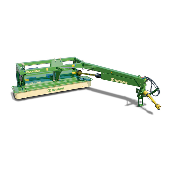
- Page 1 Disc Mower EasyCut 2801 CV EasyCut 3201 CV EasyCut 3600 CV (from serial no.: 856 826) Order no.: 150 000 110 02 en 10.12.2012...
- Page 2 Krone disc mower Machine: Type / Types: EasyCut 2801 CV, EasyCut 3201 CV, EasyCut 3600 CV to which this declaration refers is in compliance with the relevant provisions of EC Directive 2006/42/EC (Machinery) The signing Managing Director is authorised to compile the technical documents.
-
Page 3: Table Of Contents
Table of Contents Pos : 4 /Ü berschriften/Ü bers chriften 1/F-J/Inhalts verzeic hnis @ 31\mod_1251969952727_78.doc x @ 302165 @ 1 @ 1 Table of Contents Pos : 5 /BA/Inhalts verz eichnis Spr ac henneutr al @ 10\mod_1221574899104_0.doc x @ 135495 @ @ 1 Table of Contents ...........................3 Foreword ..............................6 Introduction.............................7... - Page 4 Table of Contents Install the PTO shaft ........................34 Intermediate PTO shaft........................35 Using the safety chain ........................36 6.10 Swivelling parking support into transport position ................37 Driving and Transport ..........................38 Switching from working position to transport position ..............39 Clamp and Buffer..........................
- Page 5 Table of Contents 10.10.3 Aligning the Cutter Bar......................70 10.11 Checking the Cutter Blades and Blade Holder ................72 10.11.1 Cutter Blades ........................... 72 10.11.2 Blade screw connection......................73 10.11.3 Blade Quick-Fit Device ......................74 10.11.4 Periodical Inspection of the Leaf Springs ................75 10.11.5 Periodical Inspection of the Cutting Discs / Blade Drums ............
-
Page 6: Foreword
Pos : 7.2 /BA/Vor wort/Eas yC ut/Verehrter Kunde Eas yC ut @ 3\mod_1204546394934_78.doc x @ 70529 @ @ 1 Dear Customer! By purchasing the disc mower, you have acquired a quality product made by KRONE. We are grateful for the confidence you have invested in us in buying this machine. -
Page 7: Introduction
These operating instructions apply to disc mowers of the series: EasyCut 2801 CV, EasyCut 3201 CV; EasyCut 3600 CV Pos : 9.5 /Ü bers chriften/Ü bersc hriften 3/A- E/Ans pr echpartner @ 0\mod_1195569394286_78.doc x @ 839 @ 3 @ 1 3.2.1... -
Page 8: Identification Plate
Note Authentic KRONE spare parts and accessories authorised by the manufacturer help to ensure safety. The use of spare parts, accessories or additional equipment not manufactured, tested or approved by KRONE will exclude any liability for consequential damage. -
Page 9: Intended Use
Introduction Pos : 9.12.1 /Übersc hriften/Übersc hriften 2/A-E/Besti mmungsgemäß er Gebrauch (alt) @ 0\mod_1196401545090_78.doc x @ 7728 @ 2 @ 1 Intended Use Pos : 9.12.2 /BA/Einl eitung/Besti mmungsgemäßer Gebrauc h/Eas yCut/Bes timmungsgemäß er Gebrauc h (Ei nz ahl) @ 3\mod_1204548357809_78.doc x @ 70671 @ @ 1 The disc mower is built exclusively for customary use in agricultural work (intended use). - Page 10 Introduction Pos : 11 /BA/Di es e Seite is t bewusst fr eigelass en worden. @ 1\mod_1201783680373_78.doc x @ 54443 @ @ 1 This page has been left blank deliberately!! Pos : 12 /BA/---------------Seitenumbruc h---------------- @ 0\mod_1196175311226_0.doc x @ 4165 @ @ 1...
-
Page 11: Safety
Safety Pos : 13.1 /Übersc hriften/Übersc hriften 1/P-T/Sicher heit @ 0\mod_1195566748646_78.doc x @ 635 @ 1 @ 1 Safety Pos : 13.2 /BA/Sicher heit/Überar bei tete Warnhinweis e/Kennzeic hnung von Hinweisen i n der Betriebs anl eitung Einführungstext (2012- 07- 27 09:59:06) @ 0\mod_1195637804826_78.doc x @ 1098 @ 2 @ 1 Identifying Symbols in the Operating Instructions The safety instructions contained in this manual which could result in personal injury if not followed are identified by the general danger sign:... -
Page 12: Personnel Qualification And Training
Safety Pos : 13.6.1 /BA/Sicherheit/Personalqualifi kati on und -sc hul ung @ 0\mod_1195639383185_78.doc x @ 1136 @ 3 @ 1 4.2.1 Personnel Qualification and Training The machine may be used, maintained and repaired only by persons who are familiar with it and have been instructed about the dangers connected with it. -
Page 13: Safety Instructions And Accident Prevention Regulations
Safety Pos : 13.6.5 /BA/Sicherheit/Sic her hei ts- und U nfall ver hütungs-Vorschriften Swadro_Ladewag en_Eas yC ut @ 73\mod_1308298589597_78.doc x @ 655493 @ 2 @ 1 Safety Instructions and Accident Prevention Regulations Please follow all generally applicable safety and accident prevention regulations in addition to the safety instructions contained in these operating instructions! The attached warning and safety signs provide important information for safe operation. -
Page 14: Hitched Implements
Safety Parts operated by external power (e.g. hydraulically) can cause crushing and shearing injuries! Before leaving the tractor, lower the implement onto the ground, apply the parking brake, switch off the engine and remove the ignition key! Pos : 13.6.6 /BA/Sicherheit/Angehängte Geräte/Geräte angehängt @ 0\mod_1199699679381_78.doc x @ 33245 @ 2 @ 1 Hitched Implements 1... -
Page 15: Pto Operation
Safety Pos : 13.6.8 /BA/Sicherheit/Zapfwellenbetri eb Traktor @ 0\mod_1199699899350_78.doc x @ 33264 @ 2 @ 1 PTO operation 1 Use only PTO shafts specified by the manufacturer! 2 The guard tube and guard cone of the PTO shaft and the PTO guard must be attached and in good working condition (on the implement side, too)! 3... -
Page 16: Hydraulic System
Safety Pos : 13.6.11 /BA/Sic herheit/H ydrauli kanl age @ 2\mod_1203503691986_78.doc x @ 66225 @ 2 @ 1 Hydraulic system 1 The hydraulic system is pressurised! 2 When connecting hydraulic cylinders and motors, make sure the hydraulic hoses are connected as specified! 3... -
Page 17: Maintenance
Replacement parts must at least comply with the technical requirements set by the manufacturer of the implements! This is guaranteed by original KRONE spare parts! Only use nitrogen for filling pneumatic accumulators - risk of explosion! Pos : 13.6.17 /BA/Sic herheit/Wartung/Wartung Z usatz bei Gass peicherung @ 38\mod_1265787178167_78.doc x @ 349311 @ @ 1... -
Page 18: Unauthorised Conversion/Modification And Spare Parts Production
Safety Pos : 13.6.19 /BA/Sic herheit/Eigenmäc htiger U mbau und Ers atz teil hers tell ung @ 1\mod_1201937705539_78.doc x @ 55745 @ 2 @ 1 Unauthorised Conversion/Modification and Spare Parts Production Conversions or modifications of the machine are permitted only with prior consultation with the manufacturer. -
Page 19: Introduction
Safety Pos : 13.8 /BA/Sicher heit/Eas yC ut/Sic her hei t Ei nführ ung Eas yC ut @ 3\mod_1204553763950_78.doc x @ 70812 @ 2 @ 1 4.11 Introduction The disc mower is equipped with all safety devices (protective devices). However, it is not possible to eliminate all potential hazards on this machine as this would impair its full functional capability. -
Page 20: Position Of The Adhesive Safety Stickers On The Machine
Safety Pos : 13.11 /Ü bersc hriften/Ü berschriften 2/K-O/Lage der Sic her hei tsaufkl eber an der M asc hine @ 0\mod_1195634967326_78.doc x @ 1020 @ 2 @ 1 4.12 Position of the Adhesive Safety Stickers on the Machine Pos : 13.12 /BA/Sic herheit/Aufkleber/Eas yC ut/Sic her heitsaufkl eber Eas yC ut 2801/3201 @ 38\mod_1265799616933_78.doc x @ 349415 @ @ 1 RH + LH EC-308-0 Fig. - Page 21 Safety 1) On the beige gearbox 1) On the green gearbox The PTO speeds must not exceed 540 rpm! The The PTO speeds must not exceed 1000 rpm! operating pressure of the hydraulic system must The operating pressure of the hydraulic system not exceed 200 bar! must not exceed 200 bar! 939 100-4...
-
Page 22: Re-Ordering The Adhesive Safety And Information Labels
Safety Pos : 13.14 /BA/Sic herheit/Ü berarbeitete Warnhinweise/Nachbestellung/Nac hbes tell ung/ Anbri ngung Aufkl eber (2012- 07- 26 14:46:05) @ 0\mod_1195637337107_78.doc x @ 1079 @ 33 @ 1 4.12.1 Re-Ordering the Adhesive Safety and Information Labels Note Every adhesive safety and information label is assigned an order number and can be ordered directly from the manufacturer or from an authorized dealer (see Section "Contact"). -
Page 23: Commissioning
Commissioning Pos : 16.1 /Übersc hriften/Übersc hriften 1/A-E/Ers tinbetriebnahme @ 0\mod_1196314201498_78.doc x @ 5855 @ 1 @ 1 Commissioning Pos : 16.2 /Übersc hriften/Übersc hriften 2/A-E/Ers tmontage @ 1\mod_1202226261982_78.doc x @ 58270 @ 2 @ 1 First installation Pos : 16.3 /BA/Inbetriebnahme/Ersti nbetri ebnahme/Erstmontage @ 1\mod_1202224111998_78.doc x @ 58190 @ @ 1 The document "Assembly Instructions"... -
Page 24: Mounting Onto The Tractor
Commissioning Pos : 16.9 /Übersc hriften/Übersc hriften 2/A-E/Anbau an den Traktor @ 0\mod_1199717845194_78.doc x @ 34039 @ 2 @ 1 Mounting onto the Tractor Pos : 16.10 /BA/Sic herheit/Gefahrenhinweise/Mähwer ke/Gefahr - U nbeabsichtigtes Abkuppeln angehängte @ 10\mod_1221811842601_78.doc x @ 137877 @ @ 1 Danger! - Inadvertent uncoupling of the machine during road travel or work. -
Page 25: Pto Shaft
Commissioning Pos : 16.15 /Ü bersc hriften/Ü berschriften 2/F-J /Gelenkwelle @ 0\mod_1199781879794_78.doc x @ 34542 @ 2 @ 1 PTO shaft Pos : 16.16 /Ü bersc hriften/Ü berschriften 3/K-O/Längenanpass ung @ 1\mod_1201687632810_78.doc x @ 53589 @ 3 @ 1 5.4.1 Length adjustment Pos : 16.17 /BA/Inbetri ebnahme/Erstinbetriebnahme/Gelenkwelle/M ähwer keLängenanpas sung Bil d EC2800/3200 @ 10\mod_1221814571820_78.doc x @ 138104 @ @ 1 EC-0-026... -
Page 26: Install The Pto Shaft
Commissioning Pos : 16.21 /Ü bersc hriften/Ü berschriften 2/F-J /Gelenkwelle montier en @ 2\mod_1202398342788_78.doc x @ 59253 @ 2 @ 1 Install the PTO shaft Pos : 16.22 /BA/Inbetri ebnahme/Erstinbetriebnahme/Gelenkwelle/M ähwer keAnbau Gel enkwell e masc hinens eitig Bild EC 2800/3200 @ 10\mod_1221815178476_78.doc x @ 138126 @ @ 1 Figure 5 Pos : 16.23 /BA/Inbetri ebnahme/Erstinbetriebnahme/Gelenkwelle/M ähwer keAnbau Gel enkwell e masc hinens eitig T ext EC 2800/3200 @ 10\mod_1221815274211_78.doc x @ 138148 @ @ 1 •... -
Page 27: Height Of Tractor Lower Suspension Arms
Commissioning Pos : 16.27 /Ü bersc hriften/Ü berschriften 2/F-J /Höhe der Tr aktorunterlenker @ 35\mod_1257862892625_78.doc x @ 332062 @ 2 @ 1 Height of tractor lower suspension arms Pos : 16.28 /BA/Inbetri ebnahme/Erstinbetriebnahme/Eas yC ut/Höhe der Tr aktorunterlenker EC 2800/3200 @ 10\mod_1221814322211_78.doc x @ 138082 @ @ 1 Fig. -
Page 28: Start-Up
Start-up Pos : 18.1 /Übersc hriften/Übersc hriften 1/F-J/Inbetri ebnahme @ 0\mod_1196327075811_78.doc x @ 6375 @ 1 @ 1 Start-up Pos : 18.2 /Übersc hriften/Übersc hriften 2/A-E/Anbau an den Traktor @ 0\mod_1199717845194_78.doc x @ 34039 @ 2 @ 1 Mounting onto the Tractor Pos : 18.3 /BA/Sicher heit/Gefahr enhi nweis e/M ähwer ke/Gefahr - Unbeabsic htigtes Abkuppeln angebaute @ 9\mod_1220537942289_78.doc x @ 126969 @ @ 1 Danger! - Inadvertent uncoupling of the machine during road travel or work. -
Page 29: Hydraulics
Start-up Pos : 18.6 /Übersc hriften/Übersc hriften 2/F-J/H ydrauli k @ 0\mod_1199776034950_78.doc x @ 34205 @ 2 @ 1 Hydraulics Pos : 18.7 /Übersc hriften/Übersc hriften 3/P-T/Spezi elle Sic her heitshi nweis e @ 0\mod_1197301069931_78.doc x @ 17662 @ 3 @ 1 6.2.1 Special Safety Instructions Pos : 18.8 /BA/Sicher heit/H ydr aulik/War nung - Ansc hl uss der H ydr auli kl eitung en @ 0\mod_1199776548685_78.doc x @ 34225 @ @ 1... - Page 30 Start-up Pos : 18.13 /BA/Inbetri ebnahme/Eas yCut/H ydrauli k/H ydrauli kansc hluss Bild EC 2800/3200 @ 10\mod_1222069773288_78.doc x @ 138632 @ @ 1 Figure 8 Pos : 18.14 /BA/Inbetri ebnahme/Hi nweis H ydr auli kaufkl eber beac hten @ 175\mod_1371705374532_78.doc x @ 1491925 @ @ 1 Note Connect the hydraulic lines correctly •...
-
Page 31: Connecting The Electrical Controls
Start-up Pos : 18.20 /Ü bersc hriften/Ü berschriften 2/A-E/Ansc hluss der elektrischen Bedienung @ 2\mod_1202396974288_78.doc x @ 59195 @ 2 @ 1 Connecting the electrical controls Pos : 18.21 /BA/Inbetri ebnahme/Eas yCut/Ansc hl uss el ektrisc he Bedienung EC 2800/3200/3210/4013/7540/9140 @ 10\mod_1222070141960_78.doc x @ 138652 @ @ 1 The connection of the electrical controls is performed by means of the power supply cable •... -
Page 32: Lighting
Start-up Pos : 18.24 /Ü bersc hriften/Ü berschriften 2/A-E/Beleuc htung @ 0\mod_1195658399935_78.doc x @ 1881 @ 2 @ 1 Lighting Pos : 18.25 /BA/Sic herheit/F ahren und Tr ansport/Bel euchtung/Bel euc htungsanlage all e M asc hinen @ 7\mod_1215519058839_78.doc x @ 103206 @ @ 1 Danger! - Lighting system Effect: Danger to life, serious injuries or serious damage to the machine. -
Page 33: Pto Shaft
Start-up Pos : 18.31 /Ü bersc hriften/Ü berschriften 2/F-J /Gelenkwelle @ 0\mod_1199781879794_78.doc x @ 34542 @ 2 @ 1 PTO shaft Pos : 18.32 /BA/Sic herheit/Gel enkwell e/Gefahr - Sic h drehende Gel enkwelle_2 @ 0\mod_1199781692950_78.doc x @ 34523 @ @ 1 Danger! - Rotating PTO shaft Effect: Danger to life or serious injuries •... -
Page 34: Install The Pto Shaft
Start-up Pos : 18.36 /Ü bersc hriften/Ü berschriften 2/F-J /Gelenkwelle montier en @ 2\mod_1202398342788_78.doc x @ 59253 @ 2 @ 1 Install the PTO shaft Pos : 18.37 /BA/Inbetri ebnahme/Erstinbetriebnahme/Gelenkwelle/M ähwer ke/Anbau Gelenkwelle traktors eitig Bil d EC2800/3200 @ 10\mod_1221817267351_78.doc x @ 138215 @ @ 1 Figure 10 Pos : 18.38 /BA/Inbetri ebnahme/Eas yCut/Anbau Gel enkwell e/Anbau Gelenkwelle gez ogene/angehängte Eas yC uts @ 9\mod_1220874876438_78.doc x @ 128292 @ @ 1 •... -
Page 35: Intermediate Pto Shaft
Start-up Pos : 18.40 /Ü bersc hriften/Ü berschriften 2/U-Z/Z wi schengelenkwelle @ 3\mod_1204702241039_78.doc x @ 71481 @ 2 @ 1 Intermediate PTO shaft Pos : 18.41 /BA/Inbetri ebnahme/Eas yCut/Anbau Gel enkwell e/Achtung Frontschutz her unter kl appen EC 2800/3200 @ 10\mod_1222069553679_78.doc x @ 138611 @ @ 1 Caution! - Make certain the front guard (5) is folded down. -
Page 36: Using The Safety Chain
Start-up Pos : 18.46.1 /Ü berschriften/Ü berschriften 2/P-T/Sic herheits kette ver wenden @ 6\mod_1214542336632_78.doc x @ 94799 @ @ 1 Using the safety chain Pos : 18.46.2 /BA/Inbetri ebnahme/Sicherheits kette USA/WARNUNG - Falsc h di mensi oni erte Sic herungs kette ver wendet mit Vari ante @ 180\mod_1376576652355_78.doc x @ 1547873 @ @ 1 WARNING! When using a wrongly dimensioned safety chain, the safety chain may tear if the machine loosens unintentionally. -
Page 37: Swivelling Parking Support Into Transport Position
Start-up Pos : 18.48 /Ü bersc hriften/Ü berschriften 2/A-E/Abstellstütz e in Trans portstellung schwenken @ 10\mod_1221637347634_78.doc x @ 135539 @ @ 1 6.10 Swivelling parking support into transport position Pos : 18.49 /BA/Bedienung /Eas yC ut/Abstellstütze/Abstellstütz e eing eklappt Bild EC 2800/3200 @ 10\mod_1222154451514_78.doc x @ 138967 @ 2 @ 1 Figure 14 Pos : 18.50 /BA/Bedienung /Eas yC ut/Abstellstütze/Abstellstütz e i n Tr ans portstellung sc hwenken @ 12\mod_1223983226897_78.doc x @ 149837 @ @ 1 After the machine is attached, swivel the parking support into transport position. -
Page 38: Driving And Transport
Driving and Transport Pos : 20.1 /Übersc hriften/Übersc hriften 1/F-J/F ahr en und Trans port @ 0\mod_1196330049217_78.doc x @ 6553 @ @ 1 Driving and Transport Pos : 20.2 /BA/Sicher heit/Fahren und Trans port/Trans port / Straßenfahr t EC 280/320 @ 9\mod_1220877391360_78.doc x @ 128356 @ @ 1 Danger! - Transport / road travel Effect: Danger to life, serious injuries or serious damage to the machine. -
Page 39: Switching From Working Position To Transport Position
Driving and Transport Pos : 20.6 /Übersc hriften/Übersc hriften 2/U-Z/Von Ar bei tsstellung in Trans portstell ung @ 2\mod_1202466246542_78.doc x @ 59681 @ 1 @ 1 Switching from working position to transport position Pos : 20.7 /BA/Sicher heit/Fahren und Trans port/U msc hwenken des M ähwer ks in Tr ansports tell ung EC 2800/3200 @ 10\mod_1222072287851_78.doc x @ 138742 @ 2 @ 1 Danger! - Swinging the mowing unit up into transport position Effect: Danger to life or serious injuries. -
Page 40: Clamp And Buffer
Driving and Transport Pos : 20.11 /BA/F ahr en und Trans por t/Eas yC ut/Sc hutz e i n Trans por tstellung bring en EC 2801 C V /3201 C V @ 38\mod_1265698284355_78.doc x @ 348958 @ @ 1 EC-304-0 Fig. -
Page 41: Operation
Operation Pos : 22.1 /Übersc hriften/Übersc hriften 1/A-E/Bedienung @ 0\mod_1199789505403_78.doc x @ 34825 @ @ 1 Operation Pos : 22.2 /Übersc hriften/Übersc hriften 2/U-Z/Von Trans por t in Ar beitsstellung @ 2\mod_1202466185276_78.doc x @ 59662 @ @ 1 From transport into working position Pos : 22.3 /BA/Sicher heit/Gefahr enhi nweis e/M ähwer ke/Gefahr - Abs enken des Mähwer ks i n Arbeitsstellung EC 2800/3200 @ 10\mod_1222151052201_78.doc x @ 138855 @ @ 1 Danger! - Swivelling the mowing unit into working position Effect: Danger to life, injuries or damage to the machine. -
Page 42: Before Mowing
Operation Pos : 22.7 /Übersc hriften/Übersc hriften 2/U-Z/Vor dem Mähei ns atz @ 3\mod_1204788384465_78.doc x @ 73168 @ @ 1 Before mowing Pos : 22.8 /BA/Sicher heit/Gefahr enhi nweis e/M ähwer ke/Gefahr - Ar bei tsei ns atz / M ähen @ 73\mod_1307695972255_78.doc x @ 654926 @ @ 1 DANGER! - Using the machine for work Effect: Danger to life, injuries or damage to the machine. -
Page 43: Folding Down The Safety Device
Operation Pos : 22.12 /BA/Bedienung /Eas yC ut/M asc hine is t für Vor wärtsfahrt konzi piert. @ 10\mod_1222262401875_78.doc x @ 139354 @ @ 1 Warning! - Do not drive in reverse when using the machine for work. Effect: Damage to the machine. The machine is designed to travel forwards. -
Page 44: Swivelling Parking Support Into Transport Position
Operation Pos : 22.19 /Ü bersc hriften/Ü berschriften 2/A-E/Abstellstütz e in Trans portstellung schwenken @ 10\mod_1221637347634_78.doc x @ 135539 @ 2 @ 1 Swivelling parking support into transport position Pos : 22.20 /BA/Bedienung /Eas yC ut/Abstellstütze/Ac htung Abs tellstütze ei ngekl appt EC 280/320 CV- Q @ 10\mod_1221637532743_78.doc x @ 135563 @ @ 1 Caution! - Parking support(s) not swivelled into transport position before road/transport travel and for work! Effect: Damage to the machine... -
Page 45: Function Of The Switches On The Control Unit
Operation Pos : 22.25 /Ü bersc hriften/Ü berschriften 2/F-J /Funkti on der Sc halter Bedieneinhei t @ 35\mod_1257922602863_78.doc x @ 333387 @ @ 1 Function of the switches on the control unit Pos : 22.26 /BA/Bedienung /Eas yC ut/F unkti on der Schalter Bedienei nheit EC 2800/3200 @ 10\mod_1222155191780_78.doc x @ 139011 @ @ 1 Fig. -
Page 46: Detaching The Machine
Operation Pos : 22.28 /Ü bersc hriften/Ü berschriften 2/A-E/Abbau der M asc hine @ 3\mod_1204792387824_78.doc x @ 73245 @ 1 @ 1 Detaching the machine Pos : 22.29 /BA/Sic herheit/Eas yCut/Gefahr - M asc hine abs tell en_mit H ydr auli ksc hl auc h @ 9\mod_1220883208423_78.doc x @ 128830 @ @ 1 Danger! - Unexpected movements of the machine Effect: Danger to life, serious injuries •... - Page 47 Operation Figure 23 Pos : 22.34 /BA/Bedienung /Eas yC ut/Gel enkwell e/H ydrauli ksc hlauc h abkuppeln Text EC 2800/3200 @ 10\mod_1222158479858_78.doc x @ 139099 @ @ 1 • Close the shut-off valve (1) on the hydraulics pressure hose to the double-action hydraulic cylinder.
-
Page 48: Settings
Settings Pos : 24.1 /Übersc hriften/Übersc hriften 1/A-E/Ei nstellungen @ 0\mod_1199868783862_78.doc x @ 36141 @ 3 @ 1 Settings Pos : 24.2 /BA/Sicher heit/Gefahr enhi nweis e/Eins tell arbeiten / Eins tell ungen/Gefahr - Einstell arbeiten angebaute M asc hinen @ 6\mod_1214455875276_78.doc x @ 94250 @ @ 1 Danger! - Unexpected movements of the machine Effect: Danger to life or serious injuries. -
Page 49: Adjusting The Guards
Settings Pos : 24.8 /Übersc hriften/Übersc hriften 2/A-E/Ei nstellung der Sc hutze @ 3\mod_1204709091570_78.doc x @ 71854 @ @ 1 Adjusting the Guards Pos : 24.9 /BA/Sicher heit/Gefahr enhi nweis e/M ähwer ke/Gefahr - F ortsc hleudern von Steinen @ 84\mod_1318311844997_78.doc x @ 733435 @ @ 1 DANGER! –... -
Page 50: Front Guards
Settings Pos : 24.12 /BA/Ei nstellungen/M ähwer ke/Vor der e Schutz e @ 11\mod_1223360152282_78.doc x @ 145615 @ @ 1 9.2.2 Front guards EC-0-044 AMT4-0-033 Figure. 26 Height adjustment determined by side guards. Dimension a = 440 mm. Predefined dimension "a" on the front guard (1) offers optimum protection against ejected objects. -
Page 51: Setting Of The Ground Pressure
Settings Pos : 24.14 /Ü bersc hriften/Ü berschriften 2/A-E/Einstellung Bodendr uc k @ 10\mod_1222263655765_78.doc x @ 139441 @ @ 1 Setting of the Ground Pressure Pos : 24.15 /BA/Ei nstellungen/M ähwer ke/Eas yCut/Bodendruc k/Bodendr uc k allgemeiner T ext alle EC @ 0\mod_1196667271181_78.doc x @ 10190 @ @ 1 The ground pressure for the cutter bar is adjusted to local conditions by means of the compensation springs. -
Page 52: Adjusting The Tedder Speed
Settings Pos : 24.22 /Ü bersc hriften/Ü berschriften 2/A-E/Einstellung der Z etterdr ehz ahl @ 0\mod_1196668564463_78.doc x @ 10266 @ 2 @ 1 Adjusting the Tedder Speed Pos : 24.23 /BA/Sic herheit/Gefahrenhinweise/Ei nstellar beiten / Ei nstellungen/Gefahr - Einstellungen an der M asc hine @ 0\mod_1196668628056_78.doc x @ 10285 @ 3 @ 1 Danger! - Settings on the machine Effect: Danger to life, injuries or damage to the machine. -
Page 53: Adjusting The Conditioner Plate
Settings Pos : 24.27 /Ü bersc hriften/Ü berschriften 2/A-E/Einstellen des Aufber eitungs blec hs @ 0\mod_1196670615681_78.doc x @ 10399 @ 3 @ 1 Adjusting the conditioner plate Pos : 24.28 /BA/Ei nstellungen/M ähwer ke/Eins tell ung des Aufbereitungs bleches Bild EC 28/32 CV 280/320 C V @ 3\mod_1204713442195_78.doc x @ 72144 @ @ 1 EC-032-0 Fig. -
Page 54: Adjusting The Swath Width
Settings Pos : 24.31 /BA/Ei nstellungen/M ähwer ke/Schwadbr eite / Brei tablag e/Einstellung der Sc hwadbreite @ 3\mod_1204713615383_78.doc x @ 72164 @ 3 @ 1 Adjusting the Swath Width Two different forms of spreading are available: • Swathing • Wide spreading Pos : 24.32 /Ü... -
Page 55: Wide Spreading
Settings Pos : 24.36 /Ü bersc hriften/Ü berschriften 3/A-E/Brei tablag e @ 3\mod_1204713764351_78.doc x @ 72202 @ @ 1 9.7.2 Wide spreading Pos : 24.37 /BA/Ei nstellungen/M ähwer ke/Schwadbr eite / Brei tablag e/Breitabl age Bild EC 2800/3200/3210/4013 @ 10\mod_1222264844296_78.doc x @ 139573 @ @ 1 EC-0-122 Fig. -
Page 56: Adjustment For Swathing
Settings Pos : 24.40 /Ü bersc hriften/Ü berschriften 3/A-E/Einstellung bei Schwadablag e @ 3\mod_1204713732476_78.doc x @ 72183 @ 33 @ 1 9.7.3 Adjustment for Swathing Pos : 24.41 /Ü bersc hriften/Ü berschriften 3/P-T/Sonderausr üstung @ 0\mod_1201161230852_78.doc x @ 51084 @ 3 @ 1 9.7.4 Special equipment Pos : 24.42 /BA/Ei nstellungen/M ähwer ke/Schwadbr eite / Brei tablag e/Einstellung der Sc hwadabl age Bild EC 280/320 C V / B 1000 C V @ 103\mod_1331793832879_78.doc x @ 938098 @ @ 1... -
Page 57: Wide Spreading
Settings Pos : 24.49 /Ü bersc hriften/Ü berschriften 3/A-E/Brei tablag e @ 3\mod_1204713764351_78.doc x @ 72202 @ @ 1 9.7.5 Wide spreading Pos : 24.50 /Ü bersc hriften/Ü berschriften 3/P-T/Sonderausr üstung @ 0\mod_1201161230852_78.doc x @ 51084 @ @ 1 9.7.6 Special equipment Pos : 24.51 /BA/Ei nstellungen/M ähwer ke/Schwadbr eite / Brei tablag e/Kreuzgriffe Hinweis @ 59\mod_1297431749350_78.doc x @ 558246 @ @ 1 Note... -
Page 58: Setting Wide Distributor Plate
Settings Pos : 24.56 /BA/Ei nstellungen/M ähwer ke/Schwadbr eite / Brei tablag e/Breitverteilerbl ec h eins tell en @ 60\mod_1297859420539_78.doc x @ 561604 @ 2 @ 1 9.7.7 Setting wide distributor plate Pos : 24.57 /BA/Ei nstellungen/M ähwer ke/Schwadbr eite / Brei tablag e/Breitverteilerbl ec h Bild @ 60\mod_1297859267403_78.doc x @ 561578 @ @ 1 EC-382-0 Fig. -
Page 59: Maintenance
Maintenance Pos : 26.1 /Übersc hriften/Übersc hriften 1/U-Z/Wartung @ 0\mod_1199883581050_78.doc x @ 36685 @ 22 @ 1 Maintenance Pos : 26.2 /Übersc hriften/Übersc hriften 2/P-T/Spezi elle Sic her heitshi nweis e @ 0\mod_1196660495760_78.doc x @ 9134 @ @ 1 10.1 Special Safety Instructions Pos : 26.3 /BA/Sicher heit/Eas yC ut/Gefahr - R epar atur-,Wartungs- und R ei nigungs arbeiten @ 9\mod_1220962711787_78.doc x @ 130625 @ 2 @ 1 Danger! - When performing repair, maintenance or cleaning work on the machine, or in... -
Page 60: Spare Parts
Effect: Danger to life, serious injuries or loss of warranty claims as well as exclusion of liability • Use only authentic KRONE spare parts and accessories authorised by the manufacturer. The use of spare parts, accessories or additional equipment not manufactured, tested or approved by KRONE will exclude any liability for consequential damage. -
Page 61: Tightening Torques (Countersunk Screws)
Maintenance Pos : 26.13 /Ü bersc hriften/Ü berschriften 2/A-E/Anzugs drehmomente über Innens echs kant @ 45\mod_1277106415765_78.doc x @ 411230 @ 2 @ 1 10.4 Tightening Torques (Countersunk Screws) Pos : 26.14 /BA/War tung/Drehmomente / Anzugs momente/Dr ehmomente über Innens ec hs kant @ 45\mod_1277106232328_78.doc x @ 411205 @ @ 1 A = Thread size The tightening torque M is stated in Nm... -
Page 62: Tyres
If tyres are not correctly fitted, it could explode when pumped up. This can cause serious injury. If you do not have sufficient experience of fitting tyres, have tyres fitted by the KRONE dealer or a qualified tyre specialist. •... - Page 63 Pos : 26.19.6 /BA/Wartung/Reifen/Eas yCut/R eifen-Luftdr uc k T abell e EC 2801/3201/3600 C V @ 128\mod_1346671021134_78.doc x @ 1152664 @ @ 1 Type Tyre identification Tyre pressure [bar] EasyCut 2801 CV EasyCut 3201 CV 15.0/55-17 10 PR EasyCut 3600 CV Pos : 26.19.7 /BA/Wartung/Reifen/Eas yCut/R eifen-Anz ugsmoment T abelle EC 2800/3200 C V_CR I @ 10\mod_1222266312984_78.doc x @ 139682 @ 3 @ 1...
- Page 64 Maintenance Pos : 26.21 /BA/Diese Seite ist bewusst freigel ass en wor den. @ 1\mod_1201783680373_78.doc x @ 54443 @ @ 1 This page has been left blank deliberately!! Pos : 26.22 /BA/---------------Seitenumbr uc h---------------- @ 0\mod_1196175311226_0.doc x @ 4165 @ 2 @ 1...
-
Page 65: Filling Quantities And Lubrication Designations For Gearboxes
Input Gearbox 0.7 l Speed gearbox (CV machines) 6.8 l On request SAE 90 Cutter bar EasyCut 2801 CV 6.0 l Cutter bar EasyCut 3201 CV 7.0 l Cutter bar EasyCut 3600 CV 8.0 l Pos : 26.26 /BA/War tung/Zei tinter valle an den Getrieben 200 h @ 0\mod_1196951919921_78.doc x @ 15373 @ @ 1 10.6.1... -
Page 66: Swivel Gear
Maintenance Pos : 26.28.1 /Ü berschriften/Ü berschriften 2/P-T/Schwenkgetri ebe @ 7\mod_1215583568595_78.doc x @ 104071 @ @ 1 10.7 Swivel Gear Pos : 26.28.2 /BA/Wartung/Öl kontroll e_Wechsel/M ähwer ke/Bild Sc hwenkgetriebe oberer T eil EC 2800/3200 @ 10\mod_1222319906505_78.doc x @ 139758 @ @ 1 Figure 37 Pos : 26.28.3 /BA/Wartung/Öl kontroll e_Wechsel/Sc hwader/Schwenkg etriebe/Schwenkgetri ebe T ext oberer ( 1) @ 7\mod_1215583755173_78.doc x @ 104093 @ @ 1 The swivel gear consists of an upper (1) and lower (2) gearbox. - Page 67 Maintenance Pos : 26.28.9 /BA/Wartung/Öl kontroll e_Wechsel/Sc hwader/Schwenkg etriebe/Schwenkgetri ebe T ext unterer (2) @ 7\mod_1215583883407_78.doc x @ 104113 @ @ 1 lower (2) part of the swivel gear Pos : 26.28.10 /BA/Wartung/Öl kontr olle_Wec hs el/M ähwer ke/Bil d Schwenkgetri ebe unter er T eil EC 2800/3200 @ 10\mod_1222320414770_78.doc x @ 139780 @ 2 @ 1 Figure 38 Pos : 26.28.11 /BA/Wartung/Öl kontr olle_Wec hs el/Öl kontr olle_ALTÖl kontroll e SAE 90 @ 0\mod_1197008973815_78.doc x @ 15649 @ @ 1 Oil level check:...
-
Page 68: Input Gearbox
Maintenance Pos : 26.30.1 /Ü berschriften/Ü berschriften 2/A-E/Eing angsgetriebe @ 0\mod_1197005979596_78.doc x @ 15454 @ @ 1 10.8 Input gearbox Pos : 26.30.2 /BA/Wartung/Öl kontroll e_Wechsel/M ähwer ke/Bild Eing angsgetriebe EC 28/32 CV CRI @ 3\mod_1204725801898_78.doc x @ 72508 @ 2 @ 1 EC-0-040 Fig. -
Page 69: Speed Gearbox
Maintenance Pos : 26.32.1 /Ü berschriften/Ü berschriften 2/P-T/Schaltgetriebe @ 0\mod_1197010889455_78.doc x @ 15766 @ @ 1 10.9 Speed gearbox Pos : 26.32.2 /BA/Wartung/Öl kontroll e_Wechsel/M ähwer ke/Bild Sc hal tgetriebe EC 2800/3200 CV @ 10\mod_1222322557380_78.doc x @ 139847 @ 2 @ 1 EC-0-041-1 Figure 40 Pos : 26.32.3 /BA/Wartung/Öl kontroll e_Wechsel/Öl kontrolle_ALT Öl kontr olle SAE 90 @ 0\mod_1197008973815_78.doc x @ 15649 @ 3 @ 1... -
Page 70: Oil Level Check And Oil Change On The Cutter Bar
Maintenance Pos : 26.34.1 /Ü berschriften/Ü berschriften 2/K-O/Ölstands kontroll e und Öl wec hs el am Mähhol m @ 0\mod_1197017549815_78.doc x @ 15963 @ @ 1 10.10 Oil level check and oil change on the cutter bar Pos : 26.34.2 /Ü berschriften/Ü berschriften 3/K-O/Öl wec hs el @ 0\mod_1197021941955_78.doc x @ 16139 @ @ 1 10.10.1 Oil change Pos : 26.34.3 /BA/Wartung/Mähwerke/Hi nweis Ei n Öl wec hs el am M ähhol m ist nicht erfor derlich. - Page 71 Maintenance Pos : 26.34.10 /BA/Wartung/M ähwer ke/Öl kontr olle M ähholm Eas ycut @ 3\mod_1204723206930_78.doc x @ 72428 @ @ 1 • Allow the machine to run briefly. Do not leave the driver’s cab until the cutting discs/blade drums have come to a complete stop EC-0-003 Fig.
-
Page 72: Checking The Cutter Blades And Blade Holder
Maintenance Pos : 26.36.1 /Ü berschriften/Ü berschriften 2/K-O/Kontr olle der Mähkli ngen und M ess erhalter ung @ 0\mod_1197265641329_78.doc x @ 16323 @ 3 @ 1 10.11 Checking the Cutter Blades and Blade Holder Pos : 26.36.2 /BA/Sic herheit/Gefahrenhinweise/Mähwer ke/Gefahr - F ehlende und besc hädigte Mähkli ngen und M ähkli ngenhalterungen @ 0\mod_1197265722813_78.doc x @ 16342 @ @ 1 Warning! - Missing and damaged cutter blades and cutter blade retainers. -
Page 73: Blade Screw Connection
Maintenance Pos : 26.36.8 /BA/Wartung/Mähwerke/M ess ersc hraub / M ess ersc hnell vers chl uss/M ess ersc hraubversc hlus s H altebolzen 14 mm @ 0\mod_1197267907375_78.doc x @ 16425 @ @ 1 10.11.2 Blade screw connection Danger! - Insufficient thickness of material on the retaining bolts. Effect: Danger to life or serious injuries. -
Page 74: Blade Quick-Fit Device
Maintenance Pos : 26.36.10 /BA/Wartung/M ähwer ke/M ess erschr aub / M ess erschnellversc hlus s/M essers chnell versc hlus s H altebolzen 14mm @ 0\mod_1197268087875_78.doc x @ 16444 @ @ 1 10.11.3 Blade Quick-Fit Device Danger! - Insufficient thickness of material on the retaining bolts. Effect: Danger to life or serious injuries. -
Page 75: Periodical Inspection Of The Leaf Springs
The abrasion limit of the leaf springs will be achieved if the application seam (1) is worn on one point. EC 225 0 Fig. 46 Note Use only original Krone spare parts to replace the leaf springs. Pos : 26.36.13 /BA/---------------Seitenumbruch---------------- @ 0\mod_1196175311226_0.doc x @ 4165 @ 3 @ 1... -
Page 76: Periodical Inspection Of The Cutting Discs / Blade Drums
In case of deformed cuttings discs or drums, the dimension of A = 48 mm must never be exceeded. EC-0-211 Fig. 47 Note The cutting discs or drums must be replaced by Original Krone spare parts only. Pos : 26.36.15 /BA/---------------Seitenumbruch---------------- @ 0\mod_1196175311226_0.doc x @ 4165 @ 3 @ 1... -
Page 77: Abrasion Limit
If cutting discs or blade drums show deformations or wear in form of abrasions (2) or similar, these components have to be replaced by Original Krone spare parts . Pos : 26.36.17 /BA/---------------Seitenumbruch---------------- @ 0\mod_1196175311226_0.doc x @ 4165 @ @ 1... -
Page 78: Blade Changing On Cutting Discs
Maintenance Pos : 26.36.18 /Ü bersc hriften/Ü bersc hriften 2/K- O/Messer wec hsel an M ess ertellern @ 0\mod_1197269068562_78.doc x @ 16521 @ 3 @ 1 10.12 Blade Changing on Cutting Discs Pos : 26.36.19 /BA/Sic her hei t/Gefahrenhi nweis e/M ähwer ke/Gefahr - Schnell roti erende M ess erteller/M ess ertrommeln_1 @ 0\mod_1197017696736_78.doc x @ 16001 @ @ 1 Danger! - Rapidly rotating cutting discs/blade drums. -
Page 79: Blade Screw Connection
Maintenance Pos : 26.36.22 /Ü bersc hriften/Ü bersc hriften 3/K- O/Messers chr aubverschl uß @ 0\mod_1197270941296_78.doc x @ 16578 @ @ 1 10.12.1 Blade Screw Connection Pos : 26.36.23 /BA/Wartung/M ähwer ke/M ess erschr aub / M ess erschnellversc hlus s/Besc hr eibung M ess er wec hs el M ess erschr aubverschl uss @ 47\mod_1285661949953_78.doc x @ 456898 @ @ 1 EC-0-250 Pic. -
Page 80: Blade Quick-Fit Device
Maintenance Pos : 26.36.25 /Ü bersc hriften/Ü bersc hriften 3/K- O/Messers chnell versc hluß @ 0\mod_1197271019859_78.doc x @ 16597 @ @ 1 10.12.2 Blade Quick-Fit Device Pos : 26.36.26 /BA/Wartung/M ähwer ke/M ess erschr aub / M ess erschnellversc hlus s/Besc hr eibung M ess er wec hs el M ess erschnellversc hlus s @ 0\mod_1197271100500_78.doc x @ 16616 @ @ 1 EC-251-0 Fig. -
Page 81: Replacing The Linings
Maintenance Pos : 26.36.28 /BA/Wartung/M ähwer ke/Stoß kanten erneuern @ 0\mod_1197271320468_78.doc x @ 16636 @ @ 1 10.13 Replacing the linings Caution! - If the linings are checked irregularly. Effect: Damage to the machine • Always check the mowing unit for damaged linings prior to start-up and replace linings, if necessary! •... -
Page 82: Rotary Hub With Shear Fuse (Optional)
Maintenance Pos : 26.38.1 /Ü berschriften/Ü berschriften 2/K-O/Kreis elnabe mit Schersic her ung ( optional) @ 4\mod_1213097920976_78.doc x @ 86356 @ 3 @ 1 10.14 Rotary hub with shear fuse (optional) Pos : 26.38.2 /BA/Wartung/Mähwerke/Sc hersic herung/Bil d Mähhol m Aufstellung @ 15\mod_1232448960839_78.doc x @ 174058 @ @ 1 Fig. - Page 83 Maintenance Pos : 26.38.4 /BA/Sic herheit/Gefahrenhinweise/Mähwer ke/Gefahr - Sc hnell rotier ende Messerteller /Mess ertr ommel n_1 @ 0\mod_1197017696736_78.doc x @ 16001 @ 2 @ 1 Danger! - Rapidly rotating cutting discs/blade drums. Effect: Danger to life or serious injuries. •...
-
Page 84: After Shearing Off
Maintenance Pos : 26.38.8 /BA/Wartung/Mähwerke/Sc hersic herung/Nac h dem Absc heren Eas yCut @ 3\mod_1204205154608_78.doc x @ 69944 @ @ 1 10.14.1 After Shearing Off Caution! - Correct installation position of the bearing housing not observed. Effect: Damage to the machine •... - Page 85 • Remove the hub (1). • Remove the damaged shear pins (3). • Check the nut and hub for damage. Replace damaged parts with KRONE original replacement parts. • Fill the space above the bearing with grease (c). • Place the hub on the pinion shaft.
-
Page 86: Accumulator (Optional)
Maintenance Pos : 29.1 /Übersc hriften/Übersc hriften 2/A-E/Druc kspeic her @ 38\mod_1265705629261_78.doc x @ 349236 @ @ 1 10.15 Accumulator (optional) Pos : 29.2 /BA/Sicher heit/H ydr aulik/Gefahr Unter hohem Druc k s tehende Flüs sigkeiten. @ 38\mod_1265808735198_78.doc x @ 349461 @ @ 1 DANGER! –... - Page 87 Slightly open the shut-off valve (3) on the accumulator and reduce the pressure in the accumulator until the value for your machine type is reached (see table) Type [bar] EasyCut 2801 CV EasyCut 3201 CV • Close the shut-off valve (3) on the accumulator •...
-
Page 88: Maintenance - Lubrication Chart
Maintenance – lubrication chart Pos : 31.1 /Übersc hriften/Übersc hriften 1/U-Z/Wartung - Sc hmier plan @ 0\mod_1197359304198_78.doc x @ 18232 @ 2 @ 1 Maintenance – lubrication chart Pos : 31.2 /Übersc hriften/Übersc hriften 2/P-T/Spezi elle Sic her heitshi nweis e @ 0\mod_1196660495760_78.doc x @ 9134 @ @ 1 11.1 Special Safety Instructions Pos : 31.3 /BA/Sicher heit/Gefahr enhi nweis e/M ähwer ke/Gefahr - Reparatur_Wartung _Rei nigungs_4 allgemei n Eas yC ut @ 11\mod_1223620198301_78.doc x @ 148349 @ 2 @ 1... -
Page 89: Lubricating The Intermediate Pto Shaft
Maintenance – lubrication chart Pos : 31.7 /Übersc hriften/Übersc hriften 2/A-E/Absc hmier en der Z wisc heng elenkwlle @ 35\mod_1257933354660_78.doc x @ 334907 @ 1 @ 1 11.3 Lubricating the intermediate PTO shaft Pos : 31.8 /BA/Wartung/Gel enkwelle sc hmier enAbschmi eren Z wisc heng elenkwlle EC 2800/3200 @ 10\mod_1222323894458_78.doc x @ 139917 @ @ 1 AMT-1-023 Figure 57: The profile pipes on the intermediate PTO shaft must be lubricated every 20 operating hours. -
Page 90: Lubrication Chart
Maintenance – lubrication chart Pos : 31.10 /Ü bersc hriften/Ü berschriften 2/P-T/Schmi erpl an @ 0\mod_1197361829026_78.doc x @ 18495 @ 1 @ 1 11.4 Lubrication Chart Pos : 31.11 /BA/War tung/Mähwer ke/Eas yC ut / AM Mähwer ke/Sc hmier pläne/Sc hmi erplan EC 2801/3201 @ 38\mod_1265704530495_78.doc x @ 349214 @ 2 @ 1 EC-310-0 Figure 58:... - Page 91 Maintenance – lubrication chart (CV) (CV) EC-307-0 Figure 59: Pos : 32 /BA/---------------Seitenumbruc h---------------- @ 0\mod_1196175311226_0.doc x @ 4165 @ @ 1...
-
Page 92: Placing In Storage
Draw up a list of all replacement parts you will need. This will make it easier for your KRONE dealer to process your orders and you will be certain that your machine will be ready for use at the beginning of the next season. -
Page 93: Before The Start Of The New Season
Before the Start of the New Season Pos : 33.4 /Übersc hriften/Übersc hriften 1/U-Z/Vor Beginn der neuen Sais on @ 4\mod_1211272647559_78.doc x @ 82867 @ 2 @ 1 Before the Start of the New Season Pos : 33.5 /Übersc hriften/Übersc hriften 2/P-T/Spezi elle Sic her heitshi nweis e @ 0\mod_1196660495760_78.doc x @ 9134 @ @ 1 13.1 Special Safety Instructions Pos : 33.6 /BA/Sicher heit/Gefahr enhi nweis e/M ähwer ke/Gefahr - Reparatur_Wartung _Rei nigungs_4 allgemei n Eas yC ut @ 11\mod_1223620198301_78.doc x @ 148349 @ 2 @ 1... - Page 94 Before the Start of the New Season Pos : 33.10 /BA/Ei nlag erung/Eas yC ut / AM M ähwer ke/Vor der Saison ohne Ber eifung @ 3\mod_1204731533226_78.doc x @ 72767 @ @ 1 • Lubricate the machine thoroughly. Remove any condensation water which may have collected in the bearings.
-
Page 95: Friction Clutch
Manipulation of the overload protection changes the slip torque. This will lead to a loss of warranty claims! Original KRONE spare parts only may be used. Pos : 33.15 /BA/Ei nlag erung/Rei bkupplung/R eibkuppl ung entlüften @ 3\mod_1204732297351_78.doc x @ 72885 @ 2 @ 1 EC-257-0 Fig. -
Page 96: Special Equipment
Special equipment Pos : 35.1 /Übersc hriften/Übersc hriften 1/P-T/Sonder ausstattung @ 2\mod_1202808469779_78.doc x @ 61649 @ 2 @ 1 Special equipment Pos : 35.2 /Übersc hriften/Übersc hriften 2/P-T/Spezi elle Sic her heitshi nweis e @ 0\mod_1196660495760_78.doc x @ 9134 @ @ 1 14.1 Special Safety Instructions Pos : 35.3 /BA/Sicher heit/Gefahr enhi nweis e/M ähwer ke/Gefahr - Reparatur_Wartung _Rei nigungs_4 allgemei n Eas yC ut @ 11\mod_1223620198301_78.doc x @ 148349 @ 22 @ 1... -
Page 97: Cross Conveyor
Pos : 37.3 /BA/Sonder ausstatung/Eas yCut / AM M ähwer ke/Querförderer/Querförderer T ext allgemei n @ 10\mod_1222328367161_78.doc x @ 140095 @ 2 @ 1 The KRONE cross conveyor is equipped with all the necessary safety devices (protective devices). However, it is not possible to eliminate all the potential hazards on this additional equipment as this would impair the machine's full functional capability. -
Page 98: Position Of The Adhesive Safety Stickers On The Cross Conveyor
Special equipment Pos : 37.6 /BA/Sonder ausstatung/Eas yCut / AM M ähwer ke/Querförderer/Lage der Sic her hei tsaufkl eber am Querförderer @ 10\mod_1222331106114_78.doc x @ 140330 @ @ 1 14.5 Position of the Adhesive Safety Stickers on the Cross Conveyor Pos : 37.7 /BA/Sonder ausstatung/Eas yCut / AM M ähwer ke/Querförderer/Sicher heitsaufkl eber am Querför derer Eas yCut 2800/3200 @ 10\mod_1222330217239_78.doc x @ 140285 @ 2 @ 1 Fig. - Page 99 Special equipment Hazard due to the rapidly circulating conveyor belt. Order No. 942 200 1 (2x) 939 472-2 Danger in the swivel range of the cross conveyor. Order No. 939 472 1 (1x) While parts are moving, never reach into areas where there is a risk of being crushed.
-
Page 100: Position Of The General Information Labels On The Cross Conveyor
Special equipment Pos : 37.10 /BA/Sonderauss tatung/Eas yC ut / AM M ähwer ke/Querför der er/Lage der Hi nweis aufkl eber am Querför der er @ 10\mod_1222331157411_78.doc x @ 140351 @ @ 1 14.6 Position of the General Information Labels on the Cross Conveyor Pos : 37.11 /BA/Sonderauss tatung/Eas yC ut / AM M ähwer ke/Querför der er/Hinweis aufkleber am Querförder er EC 2800/2801 3200/3201 3210/4013 @ 39\mod_1268046213394_78.doc x @ 357743 @ @ 1 EC-191-1 Fig. -
Page 101: General
Special equipment Pos : 37.13 /BA/Sonderauss tatung/Eas yC ut / AM M ähwer ke/Querför der er/Hinweis Lage der Hinweisaufkl eber an der M asc hine beac hten @ 10\mod_1222331206426_78.doc x @ 140373 @ @ 1 Caution! - Failure to observe general information labels on the basic machine! Effect: Damage to the machine. -
Page 102: Function Of The Switches On The Control Unit
Special equipment Pos : 37.21 /Ü bersc hriften/Ü berschriften 2/F-J /Funkti on der Sc halter Bedieneinhei t @ 35\mod_1257922602863_78.doc x @ 333387 @ 3 @ 1 14.8 Function of the switches on the control unit Pos : 37.22 /BA/Bedienung /Eas yC ut/F unkti on der Schalter Bedienei nheit EC 2800/3200 @ 10\mod_1222155191780_78.doc x @ 139011 @ @ 1 Fig. -
Page 103: Setting Conveyor Belt
Special equipment Pos : 37.24 /BA/Sonderauss tatung/Eas yC ut / AM M ähwer ke/Querför der er/Ei nstellung Tr ans portband @ 10\mod_1222333861895_78.doc x @ 140480 @ @ 1 14.9 Setting Conveyor Belt The conveyor belt must be tensioned to an expansion of approx. 0.6%. EC-202-0 Figure. -
Page 104: Hydraulic System
• Repair work on the hydraulic system must only be performed by authorised KRONE professional workshops. Pos : 37.28 /Ü bersc hriften/Ü berschriften 3/F-J /Füll mengen und Sc hmier mittel bezeic hnungen @ 35\mod_1257941488816_78.doc x @ 334961 @ @ 1 14.10.1... -
Page 105: Oil Tank
Special equipment Pos : 37.32 /Ü bersc hriften/Ü berschriften 3/K-O/Ölbehälter @ 10\mod_1222335200051_78.doc x @ 140543 @ @ 1 14.10.2 Oil Tank Pos : 37.33 /BA/Sonderauss tatung/Eas yC ut / AM M ähwer ke/Querför der er/Öl behälter Bil d EC 2800/2801 3200/3201 3210/4013 @ 39\mod_1268043303394_78.doc x @ 357667 @ 3 @ 1 Figure 67 Pos : 37.34 /BA/Sonderauss tatung/Eas yC ut / AM M ähwer ke/Querför der er/Bor dhydrauli k allgemei n @ 10\mod_1222335092723_78.doc x @ 140522 @ @ 1 Pressure is supplied to the on-board hydraulic system of the machine through its own hydraulic... -
Page 106: Checking The Oil Level
Special equipment Pos : 37.37 /BA/Sonderauss tatung/Eas yC ut / AM M ähwer ke/Querför der er/H ydrauli k Öls tands kontrolle Bil d EC 2800/2801 3200/3201 3210/4013 @ 39\mod_1268042289691_78.doc x @ 357642 @ @ 1 Figure 68 Pos : 37.38 /Ü bersc hriften/Ü berschriften 3/K-O/Öl kontr olle @ 0\mod_1197021908190_78.doc x @ 16120 @ 2 @ 1 14.10.3 Checking the oil level Pos : 37.39 /BA/Sonderauss tatung/Eas yC ut / AM M ähwer ke/Querför der er/H ydrauli k-Ölstands kontroll e @ 10\mod_1222335584255_78.doc x @ 140585 @ @ 1... -
Page 107: Replacing The Hydraulic Oil Filter
Special equipment Pos : 37.43 /BA/Sonderauss tatung/Eas yC ut / AM M ähwer ke/Querför der er/H ydrauli kölfilter ersetz en EC 2800/2801 3200/3201 3210/4013 @ 39\mod_1268041642722_78.doc x @ 357617 @ @ 1 14.10.5 Replacing the hydraulic oil filter Figure 69 Note Ensure total cleanliness when changing the filter Properly dispose of filter cartridge that was removed... -
Page 108: Lubrication Points On The Cross Conveyor
Pos : 37.45 /BA/Sonderauss tatung/Eas yC ut / AM M ähwer ke/Querför der er/Schmi erstellen am Querför der band Ü bersc hrift @ 39\mod_1268035019222_78.doc x @ 357481 @ @ 1 14.11 Lubrication points on the cross conveyor Pos : 37.46 /BA/Sonderauss tatung/Eas yC ut / AM M ähwer ke/Querför der er/Schmi erstellen am QF B @ 39\mod_1268056680628_78.doc x @ 357820 @ @ 1 EC-313-0 Fig.70 === Ende der Liste für T extmar ke Inhalt ===... -
Page 109: Index
Index Index From transport into working position....41 Front guards............50 Abrasion Limit .............77 Function of the switches on the control unit45, 102 Accumulator ............86 Adjusting Skids ...........96 Adjusting the conditioner plate ......53 Height of tractor lower suspension arms ... 27 Adjusting the cutting height ........48 Hitched Implements ........... - Page 110 Position of the General Information Labels on the Start-up .............. 28 Cross Conveyor ..........100 Swath Flap Extension ........56 PTO operation ............15 Switching from working position to transport PTO shaft..........25, 33, 88 position............... 39 Purpose of Use .............7 Swivel Gear............66 Swivelling parking support into transport position ..............
- Page 112 . . konsequent, kompetent Maschinenfabrik Bernard Krone GmbH Heinrich-Krone-Straße 10, D-48480 Spelle Postfach 11 63, D-48478 Spelle Phone +49 (0) 59 77/935-0 +49 (0) 59 77/935-339 Internet: http://www.krone.de eMail: info.ldm@krone.de...
Need help?
Do you have a question about the EasyCut 2801 CV and is the answer not in the manual?
Questions and answers